











Overview
For crewed Artemis missions, the software supports both automated and manual operations as needed. The automated system can operate through loss of communication and scenarios where the system is affected by radiation.
The crew can take over manual operation of the spacecraft at any time. The Artemis II mission had several planned checkout events of manual operations, including a manual piloting demonstration with the upper stage after separation. In addition, the software has a robust command and telemetry system that provides NASA’s Mission Control Center with the insight and ability to handle unforeseen circumstances and adjust software operations.
In the event of a complete failure of all flight computers, Orion has a backup flight computer with independently developed software that will take over control. This capability covers all orbital and descent phases of flight and will ensure spacecraft and crew safety until the primary system is recovered. For critical events like reentry and orbit changing burns, the backup system can fully complete the activity independent of the primary system.
Software, in computers other than the primary flight computers, handles various other tasks, such as video processing and optical navigation. All of the software has been extensively tested in multiple laboratories and in nominal and off-nominal conditions to ensure that all the various subsystems are working together to execute the planned mission.
The Orion spacecraft houses a number of state-of-the-art avionics units to handle data generated by the systems onboard, control the various functions of the spacecraft, carry out commands sent from the Mission Control Center or the crew, and return systems telemetry for insight into systems status.
The avionics and other electronics used in Orion are almost entirely driven by software and commercial processor technologies that have been ruggedized to endure extreme radiation and temperature fluctuations. Orion’s updated avionics also can handle the severe acoustic and vibration environments associated with launch, orbit, a fiery entry into Earth’s atmosphere, and a saltwater landing.
Orion’s avionics system consists of the following subsystems:
- Command and data handling
- Guidance, navigation, control, and propulsion
- Communications and tracking
- Power
- Instrumentation
- Displays and controls
Command and Data Handling
Vehicle Management Computers
The brains of the Orion spacecraft consist of two vehicle management computers that deliver more computing power to the Orion spacecraft than any previous spacecraft designed for humans.
Each of the vehicle management computers is made up of two flight computer modules (FCMs) that oversee flight control and other software; a communication control module that allows commands and data to flow between Orion and mission control; and a display control module for the crew displays.
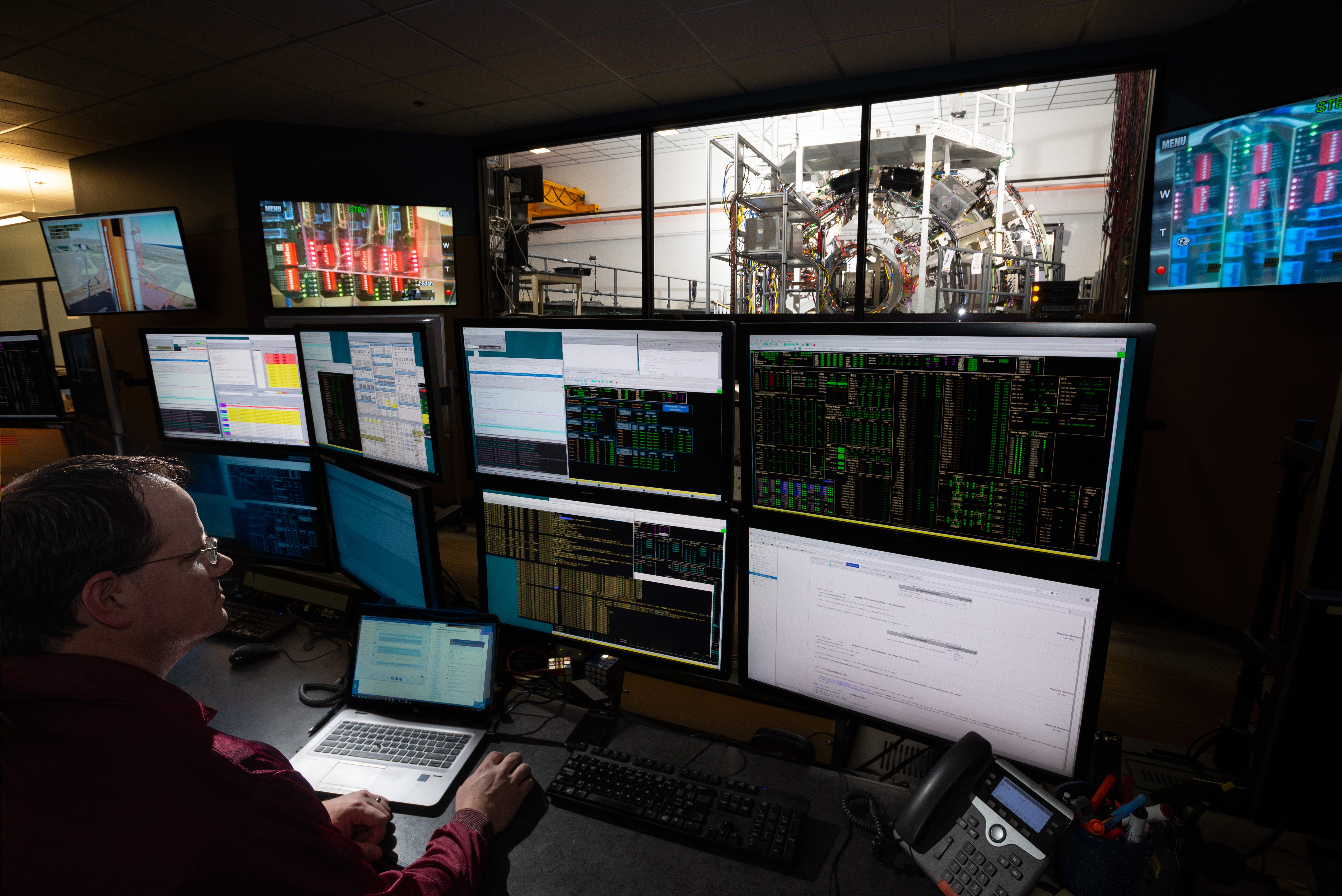
The FCMs provide a high-integrity platform to house software applications and have sufficient processing power to perform command and control of Orion. Each of the four FCMs is internally redundant and continually checks all operations to be sure they match. If the FCMs ever detect a difference between them, due to a hardware failure or a radiation upset, the different FCM “fails silent” by stopping all outputs so that a potentially corrupted FCM doesn’t issue critical commands to the spacecraft. The FCM then resets itself, listens to the other FCMs to relearn where the spacecraft is and what is happening, and then rejoins the other FCMs in controlling the spacecraft — all within 22 seconds.
Having four FCMs on the spacecraft allows the flight software to continue firing thrusters and flying as Orion transitions through the radiation environment of the Van Allen Belts.
Backup Flight Software
The four redundant FCMs greatly improve system reliability, yet Orion includes another measure of backup capability with the addition of a completely different computer, capable of running different code should it ever be needed. This capability is called the backup flight software.
In the unlikely event that something goes wrong with the primary flight computers on Orion, a dissimilar processing platform with dissimilar flight software is hosted on a system called the vision processing unit. This dissimilar computer and software provide a backup function to the redundant FCMs during critical phases of flight, with a focus on crew survival and return functions in the highly unlikely scenario in which anything renders all the FCMs ineffective. The vision processing unit also provides a place to store data during times when Orion can’t communicate with the ground.
Power and Data Units
Eight power and data units (PDU) connect the flight computers and the software to the rest of Orion. These PDUs, each of which has two cards with two redundant channels on each card, control the power to every component on the spacecraft, and they control effectors such as valves, thrusters, and heaters. All sensor data, such as temperature and pressure, is routed through the PDUs as well. The PDUs also communicate with SLS as it launches Orion and puts it on its trajectory to the Moon.
Onboard Data Network
Orion’s onboard data network is a triple-redundant network that allows the FCMs to communicate with all of the other avionic components on the spacecraft. It uses a networking technology called time-triggered gigabit ethernet that is capable of moving data at a rate 1,000 times faster than systems used on the space shuttle and space station. This networking technology allows NASA engineers to categorize different types of data and prioritize how it should travel through the onboard network. Time-critical data relating to vital systems like navigation and life support, called time-triggered data, has guaranteed bandwidth and message timing to ensure it is always delivered exactly on time. Data that is critical for delivery but not timing, such as file transfers, is called rate-constrained data and is sent immediately whenever time-triggered data is not present. Data used for non-critical tasks such as crew videoconferencing is delivered over the remaining bandwidth. The technology means that critical data and non-essential data can travel safely over a single network on board a spacecraft for the first time. It is built upon a reliable commercial data bus that has been hardened to be resilient to space radiation and proven on Orion’s Exploration Flight Test-1 and Artemis I and II missions. The data system interfaces with all components, including the service module, through radiation-hardened network switches.
Guidance, Navigation, Control, and Propulsion
The Guidance, Navigation, Control, and Propulsion (GNC&P) system is responsible for always knowing where the spacecraft is and where it is going, and it controls the propulsion system to keep Orion pointed in the proper direction and on the correct trajectory.
GNC&P Flight Software
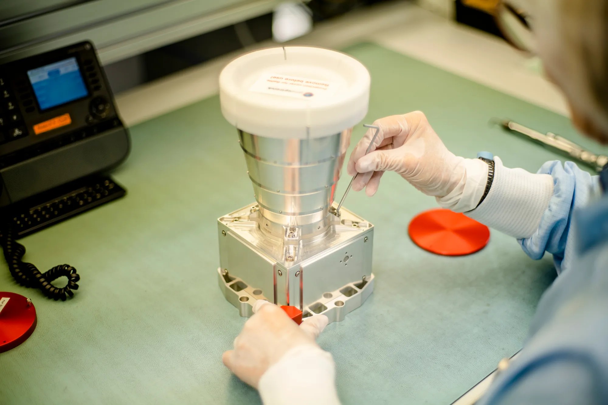
At the center of this system is the GNC&P flight software that runs on the vehicle management computers. This software receives inputs from navigation sensors and pilot controls and commands the appropriate effectors on the crew module, service module, and LAS to accomplish mission objectives.
The Orion GNC&P software operates across a variety of mission phases, including pre-launch, ascent, Earth orbit, transit to and from the Moon, entry, and various abort scenarios, as well as loiter, rendezvous, and docking. The software must operate in both manual and automated modes and must handle commands from the ground and the crew. The software must also run complex guidance and navigation algorithms while controlling highly dynamic configurations during reentry, ascent aborts, and orbital maneuvers.
Onboard Navigation System
The onboard navigation system for Orion is composed of a number of redundant sensors for measuring Orion’s position, which refers to where Orion is in space, and attitude, which refers to the direction the spacecraft is pointing. Like most systems on the spacecraft, there are usually at least two of each sensor to increase reliability of the overall system. Several different types of sensors are needed, as the spacecraft operates in the atmosphere during ascent and reentry, in low-Earth orbit, and near the Moon. These include the following:
- Orion Inertial Measurement Units: Each unit contains three devices, called gyros, that measure spacecraft body rotation rates and three accelerometers to measure spacecraft body accelerations. This inertial data is used by the vehicle management computers for onboard navigation to compute spacecraft position, velocity, and attitude.
- GPS Receivers: The GPS receivers on Orion are similar to ground-based receivers, except that these are capable of operating at the very high velocities of spaceflight. The GPS sensor system provides position and velocity updates during low-Earth orbit operations, ascent, and reentry. GPS-based altitude values are the primary triggers for entry events. Outside the range of GPS in deep space, Orion will rely on NASA’s Deep Space Network to determine the spacecraft’s location using sensitive measurements of communication signals that pass between Orion and large tracking dishes on the ground.
- Barometric Altimeter Assembly: By sensing the atmospheric air pressure outside the spacecraft during ascent and reentry, these assemblies can measure Orion’s altitude. They provide a backup altitude value for parachute and other deployments during entry.
- Star Trackers: The star tracker operates like a camera, but is much more sensitive and takes pictures only of stars. By comparing the pictures to a known star catalog, the sensor determines spacecraft attitude during orbital operations.
- Optical Navigation Camera: The optical navigation camera takes images of the Moon and Earth. By looking at the size and position of these objects in the picture, the camera can determine Orion’s range and bearing relative to that object. The optical navigation camera is part of the Orion emergency return system to autonomously operate the spacecraft in the event of lost communication with Earth.
- Sun Sensors: The Sun sensors are located on the service module and are used to determine the direction of the Sun during emergency safe mode. Knowing where the Sun is ensures that Orion can point its solar arrays in the right direction to keep power flowing to the spacecraft.

Communications and Tracking
Orion uses a high-speed communications system, employing four phased array antennas on the crew module and two phased array antennas on the service module. Phased array antennas allow signals to be controlled and directed without requiring any physical movement of the antenna. These will be used for video, data, and voice communications with the spacecraft, along with command uplink and telemetry downlink to ground stations, NASA’s Tracking and Data Relay Satellite systems, and NASA’s Deep Space Network after leaving Earth’s orbit.
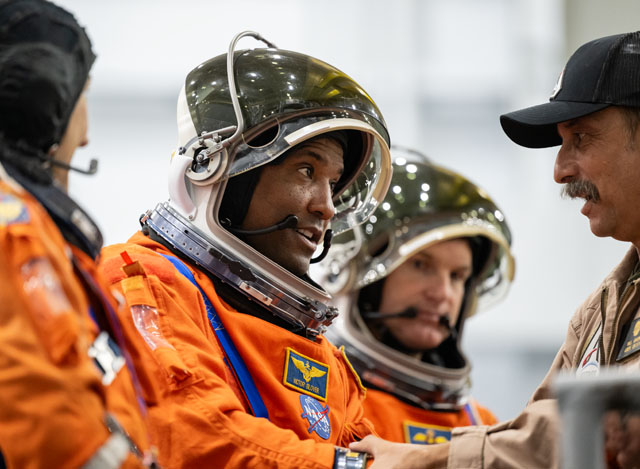
On crewed Artemis missions, the primary audio system on board will enable the crew to speak with each other and with the MCC while they are wearing spacesuits as well during the on-orbit mission phase during shirtsleeve operations. An onboard emergency communication system will allow two-way voice communications during the mission if the primary communications system fails. Search-and-rescue radios and satellite phones will be available after landing for communication with the recovery team.
Power
The Orion power system is capable of generating and supplying all of [KO1] the power that is required for its in-orbit operations. The four solar arrays, which are located on the service module, generate about 11 kilowatts of power. Power is transferred between the solar arrays and batteries and to the end systems via the power and data units.
Orion’s four main batteries are located on the crew module and use small-cell packaging technology to ensure crew safety while providing 120 volts of power to the many systems on Orion. The batteries are fully charged before launch to operate the spacecraft until the solar arrays can be deployed once in orbit. The batteries also operate the spacecraft when the solar arrays cannot be pointed at the Sun or when Orion is in the shadow of Earth or the Moon. The solar arrays are jettisoned with the service module right before entering Earth’s atmosphere, so the batteries also provide all the power needed to keep the astronauts safe for return to Earth and up to 24 hours after splashdown.
Instrumentation
Accomplishing flight test objectives requires a dedicated instrumentation system that will measure the dynamic response of all Orion subsystem performance during critical phases of the Artemis missions.
The developmental flight instrumentation (DFI) data system measures unique subsystem performance, such as spacecraft temperature and vibration, during all phases of the mission from launch, to flight in space, to return to Earth. The system is required to measure the response of newly designed components and structures to verify and validate engineering models that will be used to predict their future performance.
The architecture of the DFI system is robust and relies on proven hardware and software to deliver high reliability. The central components are data acquisition units that have two interfaces: one for the sensor interface and one for the control interface. The sensor interface communicates with the temperature, strain, accelerometers, and acoustic sensors. The control interface communicates with the power, control, recording, telemetry, and time-sync hardware. The sensors can be changed between flights to allow engineers to make adjustments based on what is learned about a previous flight.