




















Chapter Contents
- Glossary
- 6.1 Introduction
- 6.2 State-of-the-Art – Primary Structures
- 6.3 State-of-the-Art – Mechanisms
- 6.4 State-of-the-Art – Polymeric Additive Manufacturing
- 6.5 Radiation Effects and Mitigation Strategies
- 6.6 Summary
- References
Chapter Glossary
| (ABS) | Acrylonitrile Butadiene Styrene |
| (ACS3) | Advanced Composite Solar Sail System |
| (AE) | Aerospace Corporation Electron |
| (AM) | Additive manufacturing |
| (AP) | Aerospace Corporation Proton |
| (CAM) | Computer Aided Manufacturing |
| (CFRP) | Carbon Fiber Reinforced Polymers |
| (CNC) | Computerized Numerical Control |
| (COTS) | Commercial-off-the-shelf |
| (CSLI) | CubeSat Launch Initiative |
| (CTD) | Composite Technology Deployment |
| (CTE) | Coefficient of Thermal Expansion |
| (DCB) | Deployable Composite Boom |
| (DDD) | Displacement Damage Dose |
| (DLP) | Digital Light Projection |
| (DOF) | Degrees of Freedom |
| (EEE) | Electrical, Electronic and Electro-mechanical |
| (EELV) | Evolved Expendable Launch Vehicle |
| (ESD) | Electrostatic Discharge |
| (ESPA) | EELV Secondary Payload Adapter |
| (FDM) | Fused Deposition Modeling |
| (FFF) | Fused Filament Fabrication |
| (FPGAs) | Field Programmable Gate Arrays |
| (FST) | Flame, Smoke, and Toxicity |
| (GCD) | Game Changing Development |
| (GEVS) | General Environmental Verification Standard |
| (HDT) | Heat Deflection Temperature |
| (ISS) | International Space Station |
| (MOSFETs) | Metal Oxide Semiconductor Field Effect Transistors |
| (PAEK) | Polyaryletherketone |
| (PC) | Polycarbonate |
| (PCB) | Printed Circuit Board |
| (PEEK) | Polyetheretherketone |
| (PEI) | Polyetherimide |
| (PEKK) | Polyetherketoneketone |
| (PLA) | Polylactic Acid |
| (PLEO) | Polar Low-Earth Orbit |
| (RECS) | Robotic Experimental Construction Satellite |
| (ROC) | Roll Out Composite |
| (SADA) | Solar Array Drive Actuator |
| (SBIR) | Small Business Innovation Research |
| (SD) | Secure Digital |
| (SEUs) | Single Event Upsets |
| (SLA) | Stereolithography |
| (SLS) | Selective Laser Sintering |
| (SPEs) | Solar Particle Events |
| (STELOC) | Stable Tubular Extendable Lock-Out Composite |
| (TID) | Total Ionizing Dose |
| (TRL) | Technology Readiness Level |
6.1 Introduction
Material selection is a primary consideration in small spacecraft structures. Requirements for both physical properties (density, thermal expansion, and radiation resistance) and mechanical properties (modulus, strength, and toughness) must be satisfied. The typical spacecraft structure incorporates both metallic and non-metallic materials, each offering distinct advantages and limitations. Metals are generally homogeneous and isotropic, meaning properties are consistent throughout the material. Non-metals, such as composites, are inherently inhomogeneous and anisotropic, enabling properties to be tailored to specific load paths. Recently, resin photopolymer-based additive manufacturing (AM) has advanced sufficiently to create near-isotropic parts in certain applications. In general, structural materials selection is governed by the spacecraft operating environment while ensuring adequate margin for launch and operational loads. Additional considerations include thermal balance and thermal stress management. Payload or instrument sensitivity to outgassing and thermal displacements must also be considered.
AM has enabled increasingly customized structural solutions for SmallSats and demonstrated high-throughput fabrication of complex structures. Materials that were once out of reach of AM are now accessible in higher-end systems. Once only for secondary structures, AM is increasingly being applied to primary structures— particularly in CubeSat and PocketQube-class spacecraft.
However, for larger SmallSats such as Evolved Expendable Launch Vehicle (EELV) Secondary Payload Adapter (ESPA)-class, conventional machined assemblies constructed from aluminum alloys remain the dominant approach for primary structures. Secondary structures, such as solar panels, thermal blankets, and subsystems, are attached to primary structures. These structures are generally self-supporting and transmit minimal critical structural loads. Failure of a primary structure typically results in catastrophic mission failure, and while failure of a secondary structure may not compromise spacecraft integrity, it can significantly impact mission performance. These structural categories serve as a good reference but can be hard to distinguish for small spacecraft that are particularly constrained by volume. This is especially true for SmallSats since their capabilities are now comparable to full size buses, but the volume afforded by dispensers or deployment rings becomes the constraining factor. Therefore, it is imperative that structural components are as volume efficient as possible. The primary structural components need to serve multiple functions to maximize volume efficiency. Such functions may include thermal management, radiation shielding, pressure containment, and even strain actuation. These are often assigned to secondary structural components in larger spacecraft.
Structural design is influenced by subsystem integration, launch environments, mission application, and operational environment. There are different configurations for spin-stabilized and 3-axis stabilized systems, and the instrumentation used places requirements on the structure. Some instruments require mechanisms, such as deployable booms, to create enough distance between a magnetometer and the spacecraft for minimal structural effects on the measurement. The spacecraft exterior and interior material and electronic subsystems need to be understood in the specific mission environment (e.g., in-space charging effects). Mitigation for charge build-up is provided in Section 6.5.
Highly configurable or modular systems are often desirable for rapid development missions, as prototyping and firmware and software development can be extended later into the design cycle with flight hardware in the loop. Card slot systems not only provide those benefits, but when paired with certain standards, they can still fulfill the same structural, mechanical, and thermal requirements as the current CubeSat method of “stacking” electronics and payloads.
The advancement of SmallSat mechanisms, particularly in deployable structures, actuators, and switches, have increased SmallSat capabilities beyond original structural volume constraints. Deployable structures enable large structural applications with minimal volume requirements, while actuator and switch mechanisms provide motion and deployment applications.
An overview of radiation effects and some mitigation strategies is included in this chapter because radiation exposure can impact the structural design of small spacecraft. For SmallSats operating out of low-Earth orbit with increased radiation exposure, mission planners may also want to consider risk mitigation strategies associated with specific radiation environments. This includes both interplanetary missions, where solar radiation dominates, and polar low-Earth orbit (PLEO) missions, where solar radiation risk increases over the poles. In addition, the solar maximum that started in 2024 (1), which is associated with an increased number of solar particle events (SPEs), is expected to persist through 2026 and should be considered in mission planning.
The list of organizations/companies in this chapter is not all-encompassing and does not constitute an endorsement from NASA. The inclusion or omission of specific companies is not intended to reflect their technical merit or relationship with NASA. The performance advertised may differ from actual performance as the information has not been independently verified and is based on manufacturer-provided or publicly available data. It should be noted that TRL designations may vary with changes specific to the payload, mission requirements, reliability considerations, and/or the environment in which performance was demonstrated. Readers are highly encouraged to reach out to companies for further information regarding the performance and TRL of the described technology.
6.2 State-of-the-Art – Primary Structures
6.2.1 CubeSat Standard
Two general approaches are common for primary structures, often called frames or chassis, in the small spacecraft market: commercial-off-the-shelf (COTS) structures and custom-machined or additively manufactured components. Most COTS offerings are for the CubeSat market. COTS structures can simplify development, but only when mission complexity and subsystem and payload requirements fall within the design intent of a particular structure. Custom-machined structures enable greater flexibility in mission-specific system and payload design. Typical commercially available structures are designed for low-Earth orbit applications and limited mission durations, where shielding requirements are generally limited to modest radiation protection from the Van Allen belts.
| Table 6-1: CubeSat Standard Structure Dimensions | ||
|---|---|---|
| Type | Dimension (mm) | Average Weight (kg) |
| 1U | 100 x 100 x 113.5 | 0.118 |
| 1.5U | 100 x 100 x 170.2 | 0.142-0.25 |
| 2U | 100 x 100 x 227 | 0.220 |
| 3U | 100 x 100 x 340.5 | 0.352 |
| 6U | 100 x 226.3 x 366 | 0.916-1.94 |
| 12U | 226.3 x 226.3 x 366 | 1.84 |
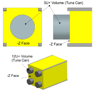
The CubeSat standard has evolved over many years of increasing use. The CubeSat standard structures, also referred to as canisterized satellites, include 1U, 1.5U, 2U, 3U, 6U, and 12U. Larger sizes exist but are less common. Table 6-1 shows the nominal weight limits and dimensions of each CubeSat structure from the CubeSat Design Specification document. There is an extra-volume (XL) option available for 3U, 6U, and 12U CubeSats; this additional volume, commonly referred to as the “tuna can” volume, is associated with an individual dispenser type. This cylindrical additional volume allows structural extensions that can accommodate various components. Steamjet Space has developed Steam Thruster, a tuna can-sized electrothermal thruster specifically designed for CubeSats. The 3U CubeSat Elfin mission used this tuna can space for antenna deployment. The Shields mission also accommodated a radiator within its tuna can volume. Figure 6.1 shows this optional volume and location on the CubeSat.
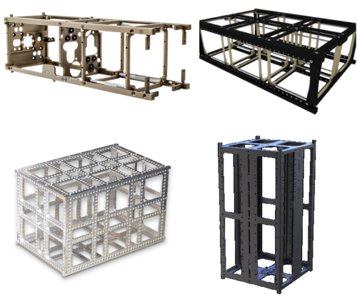
Several companies provide CubeSat primary structures. Most are machined from aluminum alloy 6061 or 7075 and are designed with several mounting locations for components to allow flexibility in spacecraft configuration. The SmallSat community has witnessed an increase in CubeSat standard configuration over the last 10 years from 1U to 3U, to include 6U and 12U. This shift has been driven by demand for greater mission capability on smaller platforms and by the need for additional volume to support more complex CubeSats designs. Table 6-2 lists several commercial primary CubeSat structures. Of the offerings included here, 1U, 3U, and 6U frames are the most prevalent; however, 12U frames are becoming more widely available as dispenser options for the 12U form factor increase. Figure 6.2 shows some commercial examples of 3U, 6U and 12U CubeSat structures.
8U and 16U CubeSat Structure
Following the market trend toward larger CubeSat structures, several companies offer configurations not formally recognized by the CubeSat standard, such as the 8U and 16U. Customized dispensers are available that will host these larger volumes.
| Table 6-2: Commercial Primary CubeSat Structures | |
|---|---|
| Manufacturer Headquarters | Structure (U) |
| 2NDSpace Italy | VERSE 1U, 2U, 3U, 6U, 8U, 12U, 16U |
| AAC Clyde Space Sweden | ZAPHOD 1U, 2U, 3U, 6U, 12U |
| C3S Electronics Development Hungary | 3U, 6U, 8U, 12U, 16U |
| Cervos Space Turkey | 1U, 2U, 3U, 6U |
| EnduroSat Bulgaria | 1U, 1.5U, 3U, 6UXL, 8U 12UXL, 16U |
| Exobotics UK | 1U, 2U, 3U, 6U, 12U, 16U |
| German Orbital Systems Germany | 1U, 2U, 3U, 6U, 12U |
| GomSpace Denmark | 3U, 6U, 8U, 12U, 16U |
| Gran Systems Taiwan | 1U, 1.5U, 2U, 3U, 6U, 6UXL, 8U, 12UXL, 16U, 27U, 64U |
| Gumush Istanbul | n-ART 1U, 2U, 3U |
| ISISPACE The Netherlands | 1U, 2U, 2UXL, 3U, 6U, 8U, 12U, 16U |
| Ishitoshi Machining Japan | MBF-1U, 3U |
| NanoAvionics Lithuania | 1U, 2U, 3U, 6U, 12U, 16U |
| Pumpkin Space Systems USA | Supernova 1U, 3U, 6U, 12U |
| NPC Spacemind Italy | SM 1U, 1.5U, 2U, 3U, 6U, 6U XL, 8U, 12U, 12U XL, 16U |
| Nara Space South Korea | 12U, 16U |
| SatRev Poland | 6U |
| Space Inventor Denmark | 3U, 6U, 8U, 12U, 16U |
6.2.2 Custom CubeSat Primary Structures
A growing development in building custom small satellites is the use of detailed interface requirement guidelines for payload and spacecraft integration. These guidelines focus on payload designs that account for rideshare safety considerations related to mission readiness and deployment methods. Safety considerations include safety switches such as the “remove before flight” pins and foot switches, and requirements that the spacecraft remain powered off while stowed in the deployment dispensers. Other safety requirements often entail anodized aluminum rails and specified limits on mass, center of gravity, and external dimensions to ensure successful canister or dispenser deployment.
DiskSat Structure
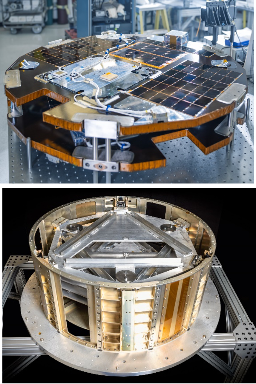
The Aerospace Corporation is developing a DiskSat (Figure 6.3) demonstration mission with support from NASA’s Space Technology Mission Directorate (STMD). The DiskSat is a 1m diameter circular disk, 2.5 cm thick, constructed as a graphite-epoxy composite sandwich, with a structural mass of less than 3 kg/m2. The volume is approximately 20 liters, equivalent to a hypothetical ‘20U’ spacecraft. While the entire volume will not be filled, the increased surface area supports power generation, aperture allocation, thermal management, and manufacturing simplification. First launch for the demonstration mission occurred in December 2025, the launch dispenser functioned as designed, communications with ground network were successful, and the mission is currently in the checkout and initialization phase (2).
6.2.3 Primary Structure Standard Dispenser
The box that houses the CubeSats in the launch vehicle is called a dispenser (or deployer), and it dispenses (or deploys) the CubeSat into the desired orbit. The CubeSat uses the entire volume of the dispenser to maximize available volume. Since CubeSats adopt a standard size and form factor, CubeSat dispensers have also been standardized with two constraint systems: rail- or tab-type. This allows spacecraft designers and launch service providers to minimize launch integration costs, increase access to space, and sustain frequent launches (3). The CubeSat Design Specification document by the CubeSat Program at Cal Poly was created to provide CubeSat developers with baseline requirements compatible with as many CubeSat dispensers and launch opportunities as possible, reducing the risk of launch interface failures (4). To view the most current versions of the CubeSat Design Specification, please visit: http://www.cubesat.org. The CubeSat Design Specification document includes rail systems. The Canisterized Satellite Dispensers (CSD) tab system created by Planetary Systems Corporation (now Rocket Lab) is the most widely available tab dispenser that offers design flexibility for structures that do not require the use of rails. See the CSD datasheet for detailed information on tab dispensers (5).
A tab-style canister deployment system uses tabs that are loaded to hold the CubeSat to a wall of the canister and are released upon deployment. The vibrational load during launch passes from the launch vehicle to the canister structure with the pre-loaded CubeSat. A CubeSat using a rail dispenser is lightly loaded on the z-axis. On the x and y axes a thin gap exists between dispenser rails and the CubeSat rails, which can cause vibrational chatter. The vibrational chatter increases the mechanical load of the CubeSat during testing and launch. For more CubeSat rail vs tab dispensers and commercial launch integration hardware, please refer to Chapter 10: Launch, Deployment, Integration, and Orbital Transport.
The required interface documents originate with the rideshare integrator for the specific dispenser being used with the launch vehicle. The launch vehicle provider typically provides the launch vibration environment. The NASA CubeSat Launch Initiative (CSLI) requires CubeSat or SmallSat systems to withstand the General Environmental Verification Standard (GEVS) vibration environment of approximately 10 Grms over a 2-minute period (6). The detailed dispenser or canister dimensional requirements provide enough information, including CAD drawings in many cases, to enable custom structural design applications.
6.2.4 CubeSat Structures Construction Methods
Monocoque Construction
Monocoque structures are load-bearing skins that have significant heritage in aircraft. On small spacecraft, the intent of this design is several-fold – maximizing internal volume, providing additional thermal mass for heat sinks or sources, enabling more mounting points, and increasing surface area to potentially reduce total ionizing dose (TID). Monocoque construction is common, and “extruded” designs are relatively easy to fabricate through computer numerical control (CNC) machining, waterjet cutting, or laser cutting.
Modular Frame Designs
Modular frames allow for a flexible internal design for rapid-development missions, while still ensuring strict adherence to external dimensions of the CubeSat standard, especially when deployment from a standardized, reusable dispenser is required. Open frames are suitable for low-Earth orbit, as radiation shielding is not provided by the structure. Care must also be taken to design for thermal mass requirements, as modular frames are inherently low in mass.
Additively Manufactured Designs
The use of additive manufacturing allows for structural designs that cannot be produced using traditional methods or would be prohibitively expensive to manufacture using conventional machining. The additive manufacturing process allows for much more design flexibility to customize structures to specific mission needs. Topology optimization methods, which generally create structures that are only feasible for additive manufacturing, can be used to minimize the amount of material and thus mass needed for the spacecraft structure. Some CubeSat missions have already flown using polymeric printed structures instead of metal, which can significantly reduce both mass and cost. Considerations need to be made regarding electrostatic discharge (ESD), grounding, and other possible electrical considerations for a polymeric frame. Additionally, fasteners for polymeric structures need to be evaluated differently than for metal, as polymers do not form threads as strong as metals and heat-set inserts may not hold well in the structure under the temperature extremes of space.
6.3 State-of-the-Art – Mechanisms
Spacecraft commonly carry onboard devices whose function is based on mechanical movement (i.e., sliding, rolling, rotating, separating, unfolding, or spinning) to either modify part of the spacecraft’s geometry or to ensure operational function of a component or instrument. These devices are known as mechanisms, and as spacecraft become more sophisticated with advances in the miniaturization of electronics and systems, their reliance on mechanisms increases significantly.
The domain of spacecraft mechanisms is quite broad, encompassing many different types across the design and operational life of a spacecraft, including moving components associated with each phase:
- Deployment: dispensing spacecraft into orbit
- Beginning of mission life: deployments of solar arrays, booms, antennas, instrumentation, etc.
- Mission maintenance: sun tracking, pointing antennas and instruments, active doors or shields, gyroscopes and reaction wheels, thrusters, etc.
- End-of-life: deorbiting methods
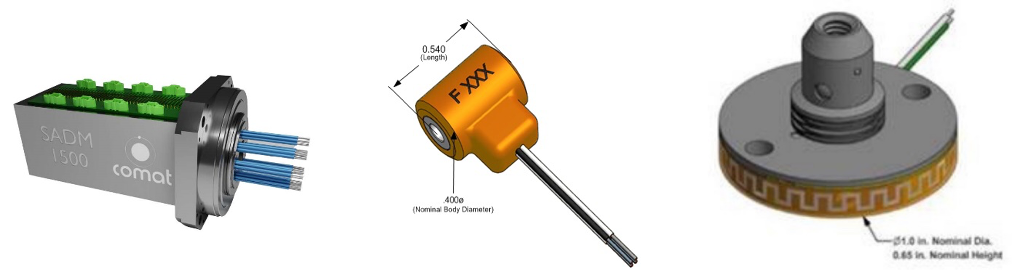
The technology within the mechanism to perform the movement is accomplished with an actuator. Depending on the actuation method, spacecraft mechanisms are either passively or actively driven. Passive mechanisms do not consume electrical energy and provide driving power via spring loading, and active mechanisms are motorized to produce driving power for mechanism operation. Most mechanisms can use both passive and active capabilities depending on the application. Table 6-4 provides an overview of common spacecraft mechanisms and examples of technologies used.
The state-of-the-art for small spacecraft mechanisms is characterized by high reliability, low power consumption, and lightweight design, and the common mechanisms listed below are considered state-of-the-art for small spacecraft use. For the purposes of this chapter, the mechanisms focus on deployable structures, robotic manipulation, release actuation, component pointing, and gimbal mechanisms. Reliability considerations are provided for optimal operational capabilities, as well as a brief explanation of the factors that affect mechanism performance.
| Table 6-4: Type of Spacecraft Mechanisms | ||
|---|---|---|
| Type of Mechanism | Description | Technology Examples |
| Separation and Release | Reliable stowage and release of spacecraft and deployable components upon an external command (active) or spring-loaded (passive). | Clamp band systems, Frangibolts, release nuts, pin pullers, bolts, burn wire, hinges, and passive spring-loaded switches |
| Motorized | Allows for rotatory motion of spacecraft components. | Solar Array Drive Assembly, directional antennas, combination of dampeners and absorbers |
| Attitude Control | Provides pointing accuracy and stability for spacecraft and components. | Reaction (momentum) wheel assembly, gimbals, component pointing, passive methods |
6.3.1 Actuators
By classical definition, actuators are devices that convert electrical, thermal, hydraulic, and/or pneumatic energy into mechanical motion when energy is applied. Active, or commanded, actuators use onboard data links and electronic control systems to determine the transfer of energy; whereas passive, or reactive, actuators allow the spacecraft environment (including external launch systems) to dictate actuator energy transfer. Table 6-5 provides some commercial actuators for SmallSats.
Specifically, spacecraft actuators are used for a variety of purposes, including:
- Attitude control and gimbaling: to control the orientation of either part (gimbaling), or all (attitude control), of a spacecraft in space. This is important for pointing sensors, instruments, and/or communications antennas in a direction required for their use.
- Attitude control general types: reaction control thrusters, momentum wheels, control moment gyros, magnetic torquers, aerodynamic control surfaces, solar sails, and gravity gradient stabilizers.
- Gimbal general types: single-axis, dual-axis, and triple-axis systems.
- Propulsion: supporting attitude control system operations, maneuvering to a new orbit, or reducing orbital velocity to begin atmospheric reentry.
- General types: chemical rocket engines (which can be the same as the upper stage launch vehicle engines), reaction control thrusters, and electric propulsion systems. These systems typically require actuated valves to operate.
- Deployment, docking and separation: extend and unfold solar panels, antennas, and other spacecraft components requiring unpacking to function.
- Deployment general types: hinge-and-spring based, linear-actuator-and-scissor-frame based, roll-out systems, and inflatable structures.
- Docking general types: probe-and-drogue, peripheral, and soft-capture systems.
- Separation general types: spring-powered or gas-powered systems.
- Thermal control: manage all or part of the spacecraft temperature. This is important for protecting internal components from extreme temperatures.
- General types: louvers, heat pipes, thermoelectric/Peltier devices, and pumped thermal fluid systems.
Mechanical actuation methods/techniques that are found in many of the above systems include:
- Electric and electromagnetic: AC/DC motor, piezoelectric ceramics, and push/pull & rotary solenoids (including solenoid valves), and microelectromechanical systems (MEMS).
- Thermal & thermoelectric: Shape memory alloys (SMA), phase-change liquids/solids (paraffin wax, liquid metals), thermofluidic gas systems, thermal bimorph structures, harmonic drive micro actuators (HMAs), thermal knife cutters, and magnesium alloy band systems.
| Table 6-5: Commercial Actuator Mechanisms | |||||
|---|---|---|---|---|---|
| Manufacturer Headquarters | Product | Mass (kg) | Size (mm) | Power Consumption | Actuation method |
| Beyond Gravity Switzerland | Separation Nut PSM 3/8B | 0.23 | 58.5x36x56 | – | – |
| Comat Space France | Solar Array Drive Mechanism – 400 | 0.465 | 83x62x46 | 4 W | Geared motor |
| Solar Array Drive Mechanism – 1500 | 3.5 | 201×132 | 13 W | Geared motor | |
| DCUBED Germany | Micro Pin Puller (uD3PP) | 0.08 | 25.5×25.5x 25.5 | – | SMA |
| Nano Pin Puller (nD3PP) | 0.025 | 17x17x17 | – | SMA | |
| Micro Release Nut (uD3RN) | 0.078 | 25x25x25 | – | SMA | |
| DHV Technology Spain | MicroSADA-10 | < 0.25 | 100x100x10 | < 6 W | Stepper Motor |
| MicroSADA-18 | < 0.95 | 226x80x18 | < 10 W | Stepper Motor | |
| SADA-M | < 2 | 155×180 | 5W (nominal) / 10W (peak) | Stepper Motor | |
| Ensign-Bickford Aerospace & Defense Company USA | TiNi™ Flat Pack FP50 | 0.033 | 2.3×1.3×0.24 | 1.25 W | SMA |
| TiNi™ FD04 Frangibolt | 0.007 | 13.72×10.16 | 15 W @ 9 VD | SMA | |
| TiNi™ ML50 | 0.010 | 25.4×16.5 | 2 W @ 7 VD | SMA | |
| TiNi™P5 Nano Pin Puller | 0.015 | 25.4×16.5 | 1.5A to 3.75A | SMA | |
| TiNi™ P5 Pin Puller | 0.018 | 28×26 | 0.5A to 2A | SMA | |
| NEA 9040 Mini | 0.030 | 28×32 | 0.4A to 1.5A | SMA | |
| NEA 1120 Pin Puller | 0.014 | 21×22 | Min 3A | Split Spool | |
| Honeybee and MMA Design USA | Solar Array Drive Actuator (SADA) | 3.1 | 127×210 | – | Stepper Motor |
| Nimesis Technology France | Triggy | 0.004-0.271 | * | * | SMA |
| Gripper | <0.032 | 39x35x7.6 | 7.4 W (ave) | SMA | |
| Moog USA | Type 2 Side-Drive Solar Array Drive Mechanism (SADM) | 5 | 234×278.6 | 15 W | – |
| Revolv Space Netherlands | Solar array drive actuator (SARA) | 0.3 | 97x97x23 | 0.5 W (idle) | – |
| Sierra Space USA | High-Output Paraffin Actuator (HOPA) | 0.35 | 44x14x14 | 5 W | Paraffin |
| C14E-TC Solar Array Drive Assembly (SADA) | 2.9 | 210x140x140 | – | Stepper Motor | |
| C14C-TC Solar Array Drive Assembly (SADA) | 2.2 | 172x140x140 | – | Stepper Motor | |
| C14 Bi-Axis Gimbal | 1.23 | 155x72x72 | – | Stepper Motor | |
| C14E Bi-Axis Gimbal | 1.72 | 221x112x112 | – | Stepper Motor | |
| ThermOmegaTech USA | High Output Paraffin Actuator (HOPA) | 1.27 | 71.2×35.56 | – | Paraffin |
| UARX Space | HADES Pico | 0.095 | 60x62x20 | 1.2A @12V | Fuse Wire |
| HADES Medius | 0.15 | 70x80x25 | 1.2A @12V | Fuse Wire | |
| HELIOS Coarse Sun Sensors | 0.01 | 32x32x11 | 0.05 W | 5V, I2C | |
| Data unknown is represented by – * See reference | |||||
6.3.2 Deployable Structures
Space deployable mechanisms are structures folded into a compact configuration and deployed into a larger predetermined shape. The development of deployable structures on spacecraft is important to enable greater mission performance. Once deployed, the structures reconfigure, changing shape and size through folding and unfolding mechanisms. Common spacecraft deployables include antennas, radiators, solar panels, gravity gradient booms, and other science instruments. Small spacecraft are well-suited for deployable structures to enhance the functionality of a compact platform. However, there are limited designs for compact, lightweight, low power deployable structures that can be folded or rolled up for launch and then self-deployed in space to support such systems on small satellites.
There are different types of deployment mechanisms to ensure the deployed structure effectively expands to the desired configuration in orbit: folding, sleeve, truss, and inflatable. Deployable solar arrays are a common folded-type of passive deployment mechanism that uses spring and hinge systems to increase available solar power for the spacecraft. Please refer to the Power chapter for deployable solar panels and arrays. The sleeve-type deployment mechanism is implemented using a rolling or sliding screw conveyor and is commonly seen on SmallSats for various antennas (30). Inflatable deployment structures are lightweight film materials typically used for larger deployed structures, like solar sails. Please refer to the Deorbit Systems chapter for deployable mechanisms used for deorbit devices.
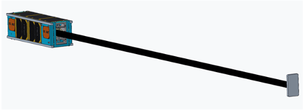
For SmallSat applications, it is common that deployable components are on a boom – a cantilever arm ejected from the spacecraft – that can perform various tasks once deployed. See Figure 6.5 for NASA’s GPX-2 CubeSat mission with a Redwire Space deployable boom to create gravity gradient stabilization as an example. SmallSat deployable structures are common and are associated with high reliability. Engineers have started developing deployables with different materials to decrease stowage volume, mass, and power. Table 6-6 lists a selection of commercially available deployable booms.
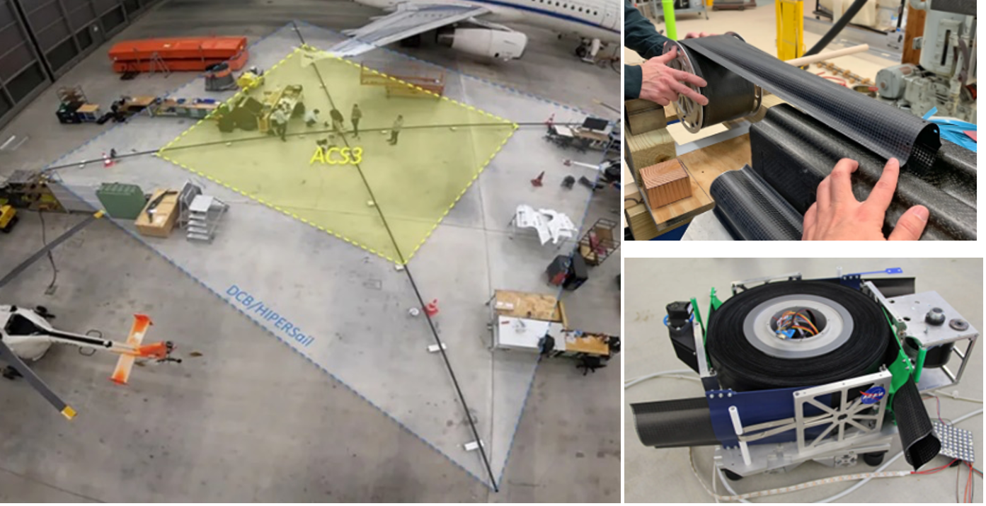
NASA Langley Research Center (LaRC) developed Deployable Composite Booms (DCB) through the Space Technology Mission Directorate (STMD) Game Changing Development (GCD) program and a joint effort with the German Aerospace Center, see Figure 6.6. DCBs have high bending and torsional stiffness, packaging efficiency, thermal stability, and 25% less weight than metallic booms (31). The Advanced Composite Solar Sail System (ACS3) project demonstrated the DCB technology for solar sailing applications after launching April 2024. The DCB/ACS3 7-m boom technology is extensible to 16.5 m deployable boom lengths (32).
Engineers have started using origami – the art of paper folding – as a strategy of deployable structure design. Origami structures are flexible in their deployment direction so that they can be easily collapsed along the same path they are deployed. One advantage of origami-inspired mechanisms is potentially faster and cheaper prototyping. Instead of relying on laser cutting or 3D-printing, prototyping of origami-inspired mechanisms can be accomplished using inexpensive materials like paper before moving to other more expensive materials. Many resources and patterns already exist that detail how designs can be created and modified or adapted for engineering purposes (33). Solar panels and arrays, solar sails, and sunshades are examples of ongoing origami engineered SmallSat components.
| Table 6-6: Commercial Deployable Booms | ||
|---|---|---|
| Manufacturer | Product | |
| Composite Technology Development | Stable Tubular Extendable Lock-Out Composite (STELOC) | |
| Oxford Space Systems | AstroTube deployable boom | |
| Redwire Space | Roll Out Composite (ROC) booms | |
| Redwire Space | CubeSat ROC Boom Deployer | |
| Redwire Space | ROC-FALL system | |
| Magellan Aerospace | Deployable Boom | |
| Rolatube Technology | Deployable Composite Booms | |
| Northrup Grumman | Coil Booms | |
| Northrup Grumman | Telescoping Tube Masts | |
6.3.3 Robotic Manipulator
The need for in-space servicing is receiving more attention from the SmallSat community with the increasing demand for more complex SmallSat systems with greater capability and longer mission lifetimes. These types of challenges are being solved with robotic manipulation systems that can perform intricate actions in space. Tasks such as repairing defunct satellites, in-orbit assembly, satellite servicing, debris capture, spacecraft system upkeep, construction, and repair are important advances for future space operations; however, these activities remain expensive and high risk. Current robotic solutions for in-space construction and repair involve humans and use very large, expensive, custom-built robotic arms with limited capabilities, such as the Canadarm. As NASA’s Artemis architecture prepares for astronaut presence in lunar and deep space missions on the Lunar Gateway, there is a growing need for more advanced and maneuverable space robotic systems. The use of these sophisticated robotic systems on a SmallSat is more attractive than traditional larger platforms as SmallSats present a more cost-effective and agile solution. A more agile robotic system can be stowed in a small volume and deployed to perform several tasks automatically or semi-automatically.
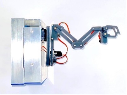
This section provides an overview of the ongoing efforts to further develop robotic systems on SmallSats. Table 6-7 lists a non-exhaustive set of ongoing developments. This type of SmallSat mechanism is maturing through research and development across government, academia, and commercial entities (42). For example, the Naval Academy Satellite Team for Autonomous Robotics (NSTAR) has developed an autonomous 3U CubeSat robotic arm system called the Robotic Experimental Construction Satellite (RECS) for testing on the ISS. RECS was launched in November 2022 (43).
| Table 6-7: Robotic Arms for Small Spacecraft | ||||||||
|---|---|---|---|---|---|---|---|---|
| Manufacturer | Product | Mass (kg) | Extendable length (mm) | Stowed Envelope (mm) | DOF | Power Consumption (W) | Actuator method | Form Factor |
| U.S. Naval Academy | 3U CubeSat with two robotic arms | 4 | 600 | 300x100x100 | 6 plus “claw” end-effector actuation | – | Stepper motor | RECS 3U (Nov 2022) |
| Redwire Space | – | – | 1 to 4 m reach | – | 5 to 7 | 8 to 65 | – | ESPA class satellites |
| Sierra Lobo | Sierra Lobo Arm (SLAC1) | – | 100x100x100 | 30x50x65 | 3 | 1.5 | – | – |
| – Represents unknown data | ||||||||
6.3.4 Reliability Considerations
Mechanisms add capabilities and complexities to small satellite design, and therefore additional integration and testing are required. NASA Reliability and Maintainability Standard (44) describes maintainability, and “test as you fly,” along with other mitigation strategies and considerations. For mechanisms, it is important to test the full subsystem and system integration levels for power consumption and subsystem dependencies. Mechanisms have lifetimes, so it is important to ensure maintainability and understand mechanism lifetime from test to flight. Because mechanisms add complexity and can introduce single-point failure risk in some instances, such as attitude control, solar panel pointing, directional antenna control, or one-time subsystem deployment switches, it is important to focus on reliability strategies. Mechanisms have contributed to over 10% of reported small satellite failures (45). Adding a mechanism to enable a mission generally increases risk.
The space environment adds to reliability considerations for operations in vacuum, plasma, or extreme thermal environments. For mechanism reliability, there are multiple steps that contribute to risk mitigation. Sarafin et al. describe a multi-step approach for a reliable mechanism design, including design simplicity, margin, supplier selection, and testing (46). The steps include guidance for torque margin for rotating components, such as solar panel and antenna pointing motors (46)(47)(48). During ground testing of mechanisms, it is important to understand mechanism lifetime to ensure the component performs throughout the planned mission duration. Materials considerations contribute to mechanism reliability in the space environment, including lubricant use and material coatings to avoid corrosion and welding of dissimilar materials (47)(48)(49). Because mechanisms are critical for advanced spacecraft capabilities, including power, communications, and science/research instruments, it is important to add mechan
6.4 State-of-the-Art – Polymeric Additive Manufacturing
Additive manufacturing (AM) processes for primary spacecraft structures have long been proposed but only recently have such methodologies been adopted for flight. AM has been common for SmallSat secondary structural elements for many years. Typically, the advantage of AM is to free the designer from constraints imposed by standard manufacturing processes and to allow for monolithic structural elements with complex geometry. In practice, additive manufacturing has a separate design space and design process, which has seen tighter integration into computer-aided design (CAD), computer-aided manufacturing (CAM), and modal and structural analysis packages in the past few years. Such tools can enable quicker turnaround times for SmallSat development and have been instrumental in mass optimization, the use of AM materials for radiation shielding, and enabling high-throughput, high-quality manufacturing. As the AM field is rapidly evolving, this section makes a best attempt to cover as many materials and printers as possible that are potentially applicable to SmallSat development.
6.4.1 Applicability of TRL to Polymer AM
While AM systems and platforms might be considered mature and of high TRL, the TRL of AM parts configured for spaceflight depends on the material, the configuration of the actual part, the manufacturing process used, the postprocessing of the manufactured part, the testing and qualification process, and many other factors. For example, nylon fabricated with a fused filament fabrication (FFF) system will have different bulk structural properties from nylon fabricated with a selective laser sintering (SLS) system. Furthermore, printer and material settings (e.g., temperature) also play a role in final part properties, meaning the same part from the same material on the same machine can have different properties if the parameters vary.
In other words, a TRL might be assignable to a component created through a particular manufacturing process with a specific material. If a particular component manufactured with nylon on an FFF system was flown to LEO successfully, the TRL for this component would be Level 7. If this component was subsequently flown on another mission manufactured with Antero 840 PEEK also on an FFF system, the TRL would still be 7. Documentation of the manufacturing process is important to properly account for the TRL. This section focuses on polymer AM and does not address metal AM for SmallSats.
6.4.2 Inspection and Testing
When new materials and/or processes are used, testing must be performed to minimize risk and bridge the gap between TRL levels. In particular, the only way to validate a tailored structure, component, or material is through testing, especially if more freedom is afforded to research and development. For new material types, if there is latitude afforded in upfront research and development, mechanical, modal, and thermal tests should be performed to compare against a known, proven baseline structural design.
6.4.3 Thermoplastics and Photopolymers
With the expansion of available open-source AM platforms in the last decade, thermoplastics and photopolymer materials have rapidly gained traction and acceptance in many applications ranging from mechanical validation and fit-checking to engineering-grade, low-rate production applications. Photopolymer or “thermoset” resins and associated manufacturing processes have improved to the point where microfluidics experiments may be additively manufactured, with the microfluidics channels and growth chambers directly manufactured as one piece, as opposed to traditional approaches of machining plastic or glass blocks.
As of publication, there are three primary methods of conducting AM for plastics: FFF (also referred to as fused deposition modeling (FDM)), which uses thermoplastics in either a spool or pellet form; stereolithography (SLA), which uses photopolymer resin; and SLS, which uses a fine powder or photoset resin. Within SLA, there are two methods of curing resin: digital light projection (DLP), which uses a very high-resolution LED matrix – a monochrome display – to cure the entire layer nearly instantly; and polyjet (also known as resin jet) which deposits resin from a line array of jets, much like an inkjet printer with a large print head.
Certain thermoplastics are quickly gaining acceptance for high-reliability parts and applications on Earth, although, as of this writing, they have yet to gain widespread acceptance for space applications. One reason for this is that AM methods cannot yet produce surfaces as smooth as machined metals, which is often a requirement for parts with tight tolerances. However, some thermoplastics are machinable, such as nylon or polyetherimide (PEI). Like the manufacture of cast iron parts, machining to a final, high tolerance specification may allow these thermoplastics to gain further acceptance.
Except for some large-format AM centers, almost all thermoplastics are manufactured in spools and may or may not be packaged for proprietary solutions. For SLA, almost all resins are used specifically for commercial solutions and dedicated AM centers. Additionally, some manufacturers may mix in additives to enhance material properties or to ease the printing process. Because of this, the following sections on each material include a table of materials for both open-source and commercial solutions, along with selected properties of interest. Availability of recommended nozzle and bed temperatures is indicative of the ability to be printed on an open-source machine, unless otherwise noted in the material description. Materials are not picked according to preference but based on the availability of technical specifications and potential applicability. For various types of AM solutions, readers are encouraged to use these sections as a rough guide for currently available commercial filaments. Additionally, the material tables will be expanded as more data is obtained for these materials.
Surface discharge, or electrostatic discharge (ESD), is a result of in-space charging effects and is caused by interactions between the space plasma environment and spacecraft materials and electronic subsystems (50). The field buildup and ESD can negatively affect the spacecraft, and there are design precautions which must be considered depending on the spacecraft’s operational environment. Per ESD guidelines from NASA Spacecraft Charging Handbook 4002A, dielectric materials above 1012 Ohm (Ω) cm should be avoided because charge accumulation occurs regardless. Please refer to the NASA Handbook 4002A, 5.2.1.5 Material Selection for more information. Historically, ESD due to faulty grounding has been a leading cause of spacecraft or subsystem failures (50). Most ESD rated thermoplastics have a surface resistivity between 106 and 109 ohms. Increasing the extrusion temperature decreases the surface resistivity.
Polylactic Acid (PLA)
PLA is the most common filament used in AM, and Table 6-7 lists several PLA filaments. It exhibits very low shrinkage and is extremely easy to print because it does not require a high-temperature bed or a heated build chamber and requires a relatively low extruder (nozzle) temperature. It also has low off-gassing during printing, which is important in open-frame AM systems in rapid prototyping environments such as lab settings. Unless the application has a very short-term exposure to harsh conditions, and if the conditions are well characterized and controlled, it is not recommended to use PLA for an application beyond TRL 3-4. For laboratory settings in controlled environments not subject to excessive mechanical forces, ESD-compatible filaments are available.
| Table 6-7: Polylactic Acid Filaments | ||||||||
|---|---|---|---|---|---|---|---|---|
| Filament Name (Citation) | ISO 75/ASTM D648 Deflection Temp (°C) | ISO 179-1 Hardness (kJ/m2) or Izod D256-10A (J/m) | ISO 527-1/ASTM D638 ZX Tensile strength (MPa) | ASTM D790/ISO 178 Flexural strength (MPa) | Nozzle Temp (°C) | Bed Temp (°C) | Density (g/cc) | ESD Risk* (Ω-cm) |
| Prusament PLA | 55 | 12 kJ/m2 | 57 | N/A | 215 | 50-60 | 1.24 | No |
| Verbatim PLA | 50 | 16 kJ/m2 | 63 | N/A | 210 | 50-60 | 1.24 | No |
| ColorFabb PLA-PHA (51) | N/A | 30 kJ/m2 | 61 | 89 | 210 | 50-60 | 1.24 | No |
| Stratasys PLA (52) | 51 | 27 kJ/m2 | 26 | 84 | N/A | N/A | 1.264 | No, 1015 |
| 3DXSTAT™ ESD-PLA | 55 | N/A | 55 | 95 | 210 | 23-60 | 1.26 | Yes, 106-109 |
Acrylonitrile Butadiene Styrene (ABS)
ABS has traditionally been the choice for higher-strength, lightweight prints from the FDM process in the open-source community. In the early days of hobbyist 3D printing, ABS was a preferred material because there was an existing supply chain making ABS filaments for weed-whackers. It is generally temperature-resistant and UV resistant but turns yellow and eventually becomes more brittle over time when exposed to sunlight. It is a moderately difficult filament to print, especially in open-frame systems. High temperature gradients during printing may cause warping as parts get larger. Enclosed AM systems with heated chambers print ABS well. For many systems, passive chamber heating is sufficient, although active heating can provide better results. Extrusion and bed temperatures for ABS tend to be slightly higher than those for PLA. Additionally, ABS shrinks 1 to 3 percent of its printed size upon cooling; the shrinkage varies from manufacturer to manufacturer and, to a lesser extent, can also be affected by the rate of cooling. ABS has flown as the complete structure for KickSat-2, a femtosat deployer for chip-scale satellites (53). The single-use design, short mission duration, and intricate dispenser frame made a conventionally machined deployer mass- and cost-prohibitive. Table 6-8 lists some examples of ABS filaments.
| Table 6-8: ABS Filaments | ||||||||
|---|---|---|---|---|---|---|---|---|
| Filament Name | ISO 75/ASTM D648 Deflection Temp (°C) | ISO 179-1 Hardness (kJ/m2) or Izod D256-10A (J/m) | ISO 527-1/ASTM D638 Tensile strength (MPa) | ASTM D790/ISO 178 Flexural strength (MPa) | Nozzle Temp (°C) | Bed Temp (°C) | Density (g/cc) | ESD Risk (Ω-cm) |
| Stratasys ABS-CF10 | 100 | 20-51 J/m | 21 | 29-69 | N/A | N/A | 1.0972 | Marginal 104-109 |
| Stratasys ABS-ESD7 | 105 | 36.2 J/m | 35 | 44 | N/A | N/A | 1.07 | Marginal 104-109 |
| 3DXSTAT™ ESD-ABS | 97 | N/A | 58 | 80 | 230 | 110 | 1.09 | Yes, 106-109 |
| Verbatim ABS | 106 (ISO 306) | 21 J/m | 47 | 78 | 240-260 | 90 | 1.05 | No |
| Kimya ABS Carbon | N/A | N/A | 36.7 | N/A | 250-260 | 90-100 | 1.05 | N/A |
Nylon
Versatile and tough, there are multiple formulations for nylon that allow for a very wide range of applications and material properties. In general, nylon is more difficult to manufacture than ABS on open-source FFF systems because it requires an enclosure for thermal stability and additional bed preparation for improved adhesion. It is also extremely hygroscopic; if possible, filament should be baked out before printing and must be kept in a dedicated dry box while printing or while being stored. Nylon and composite blends are very common because they can achieve high part strength at a lower price than many of the higher-end thermoplastics. Secondary structural pieces have been flown through the TechEdSat program using Markforged Onyx carbon fiber filaments as a flight example. Table 6-9 lists some representative examples of nylon filaments.
| Table 6-9: Nylon Filaments | ||||||||
|---|---|---|---|---|---|---|---|---|
| Filament Name (Citation) | ISO 75/ASTM D648 Deflection Temp (°C) | ISO 179-1 Hardness (kJ/m2) or Izod D256-10A (J/m) | ISO 527-1/ASTM D638 ZX Tensile strength (MPa) | ASTM D790/ISO 178 Flexural strength (MPa) | Nozzle Temp (°C) | Bed Temp (°C) | Density (g/cc) | ESD Risk (Ω-cm) |
| Taulman3D Alloy 910 (54) | 82 | N/A | 56 | N/A | 250-255 | 30-65 | N/A | Unk |
| Taulman3D Alloy 910 HDT (54) | 112 | N/A | 56 | N/A | 285-300 | 55 | N/A | Unk |
| Taulman3D Nylon 680 Food Grade (55) | N/A | N/A | 47 | N/A | 250-255 | 30-65 | N/A | No |
| Markforged Onyx ESD (56) | 138 | 44 J/m | 52 | 83 | 285 | non-heated | 1.2 | Yes, 105-107 |
| 3DXTECH CARBONX™ HTN+CF (57) | 240 | N/A | 87 | 95 | 295 | 130 | 1.24 | Marginal109 |
| Stratasys Nylon 12 (58) | 92-95 | 71-138 J/m | 33-42 | 55-57 | N/A | N/A | 1.01 | No, 1013 |
| Novamid 1030 PA-CF10 | 153-184 | N/A | 38 | 70 | 275 | 60 | 1.17 | — |
Polycarbonate (PC)
Also known as Lexan™, this thermoplastic has some of the highest impact resistance, tensile strength, and temperature resistance available for most open-source-based AM systems. After manufacturing, it is dimensionally stable and exhibits very stiff behavior. However, it is difficult to print on open-frame, open-source AM systems due to very high warping, especially when printing large components. Very high bed, chamber, and nozzle temperatures are required, and poor adhesion to the bed is a common issue. Interface adhesives are recommended to improve print-bed adhesion. It is also highly hygroscopic; if possible, the filament should be baked out before printing and kept in a dedicated dry box while printing and during storage. Certain filaments, like the Prusament PC Blend, have additives to mitigate some of the difficulties of printing PC, particularly those related to its higher temperature requirements. Table 6-10 lists some representative polycarbonate filaments.
| Table 6-10: Polycarbonate Filaments | ||||||||
|---|---|---|---|---|---|---|---|---|
| Filament Name (Citation) | ISO 75/ASTM D648 Deflection Temp (°C) | ISO 179-1 Hardness (kJ/m2) or Izod D256-10A (J/m) | ISO 527-1/ASTM D638 ZX Tensile strength (MPa) | ASTM D790/ISO 178 Flexural strength (MPa) | Nozzle Temp (°C) | Bed Temp (°C) | Density (g/cc) | ESD Risk (Ω-cm) |
| Prusament PC Blend (59) | 113 | No break for ISO 179 | 63 | 88-94 | 275 | 110 | 1.22 | No |
| Prusament PC Blend Carbon Fiber (59) | 114 | 35 kJ/m2 | 55-65 | 85-106 | 285 | 110 | 1.16 | No |
| Stratasys PC (60) | 143 | 27-77 J/m | 60 | 75 | N/A | N/A | 1.20 | No |
| Polymax PC | 99-114 | 21.5 kJ/m2 | 59.7 | 94.1 | 280 | 100 | 1.19 | — |
| 3DXtech ESD-PC | 135 | N/A | 68 | 95 | 295 | 130 | 1.24 | 107 – 109 |
| 3DXtech CF-PC | 133 | N/A | 70 | 90 | 300 | 140 | 1.36 | — |
| Polymaker PC-ABS | 106 | 25.8 kJ/m2 | 39.9 | 66.3 | 250-270 | 90-105 | 1.1 | — |
Windform
Manufactured by CRP Technology, these proprietary materials are classified as a carbon-fiber-reinforced polymer originally designed for the automotive racing industry. They are unique in that these composites are manufactured through selective laser sintering (SLS) (61). This results in higher dimensional stability and more isotropic properties than FFF, as well as the ability to produce small features slightly better than the FFF process. Windform XT 1.0 and 2.0 have been used on CubeSat and PocketQube platforms and have flight heritage through KySat-2 (launched on ELaNa IV) and TANCREDO-1 (launched through the ISS via JEM in 2017) (62). The PACE-1 CubeSat also used Windform 3D-printed components to mount optical devices. Table 6-11 lists representative CRP Windform filaments. The NASA GPX-2 Windform XT 2.0 structure launched in July 2022 and is currently operational. Some of the printed parts in the Crew Dragon spacecraft are made from Windform SP.
| Table 6-11: CRP Windform | ||||||||
|---|---|---|---|---|---|---|---|---|
| Filament Name (Citation) | ISO 75/ASTM D648 Deflection Temp (°C) | ISO 179-1 Hardness (kJ/m2) or Izod D256-10A (J/m) | ISO 527-1/ASTM D638 ZX Tensile strength (MPa) | ASTM D790/ISO 178 Flexural strength (MPa) | Manufacturing process | Bed Temp (°C) | Density (g/cc) | ESD Risk (Ω-cm) |
| Windform XT 2.0 | 173 | 4.72 kJ/m2 | 84 | 133 | N/A, SLS | N/A, SLS | 1.097 | Yes, 108 |
| Windform RS (64) | 181 | 10.8 kJ/m2 | 48-85 | 139 | SLS | SLS | 1.10 | Yes, 108 |
| Windform SP | 187 | 5.82 kJ/m2 | 76.1 | 120.1 | SLS | N/A | 1.11 | Yes, <108 |
Polyetherimide
Polyetherimide (PEI), also known by the Saudi SABIC trade name Ultem™, is a very tough thermoplastic resin with high thermal and chemical stability. It is inherently flame-resistant and can be machined. Some formulations of PEI are FAA-approved for flame, smoke, and toxicity (FST), and may also have ESD formulations. PEI is also known for extremely low off-gassing, which is crucial for optical components and sensitive scientific packages. PEI requires high nozzle and bed temperatures. For all but the smallest of parts, a heated chamber is required, with temperatures in excess of 120°C producing the best results. Due to these factors, PEI is only reliably printable on commercial FFF systems. It is also highly hygroscopic; filament should be baked out before printing and kept in a dedicated or heated dry box while both printing and in storage. PEI has similar characteristics to polyetheretherketone (PEEK), typically with slightly lower mechanical strength. PEI is a common bed material for higher-end open-source FFF systems due to its adhesive properties with other thermoplastics at higher temperatures. Ultem 1010 tends to have better mechanical properties than Ultem 9085; however it is generally more challenging to print due to lower bed adhesion. Table 6-12 lists some representative PEI filaments.
| Table 6-12: PEI Filaments | ||||||||
|---|---|---|---|---|---|---|---|---|
| Filament Name (Citation) | ISO 75/ASTM D648 Deflection Temp (°C) | ISO 179-1 Hardness (kJ/m2) or Izod D256-10A (J/m) | ISO 527-1/ASTM D638 ZX Tensile strength (MPa) | ASTM D790/ISO 178 Flexural strength (MPa) | Nozzle Temp (°C) | Bed Temp (°C) | Density (g/cc) | ESD Risk |
| THERMAX™ Ultem™ 9085 | 158 | N/A | 63 | 90 | 275 | 115 | 1.34 | No |
| 3DXSTAT™ Ultem™ 1010 CF-ESD (65) | 205 | N/A | 62 | 115 | 395 | 150 | 1.34 | Yes, 107-109 |
| Stratasys Ultem™ 1010 CG(66) | 212 | 22-27 J/m | 81 | 82-128 | N/A | N/A | 1.29 | No, 1014 |
| Stratasys Ultem™ 9085 (67) | 153 | 39-88 J/m | 69 | 80-98 | N/A | N/A | 1.27 | No, 1015 |
| Zortrax Z-PEI 9085 (68) | 186 | N/A | 54 | 90 | N/A | N/A | 1.34 | No |
| Sabic Ultem™ AM9085F | 175 | 33-104 J/m | 80 | 90 | 345 | 180 | 1.28 | 1015 |
| CarbonX CF-Ultem™ 9085 | 165 | N/A | 93 | 120 | 390 | 140 | 1.39 | — |
| CarbonX CF-Ultem™ 1010 | 205 | N/A | 145 | 120 | 385 | 140 | 1.31 | — |
PAEK
Polyetheretherketone (PEEK) and polyetherketoneketone (PEKK) – in the polyaryletherketone (PAEK) family – are the highest-performing thermoplastics developed as of this writing. With certain additives and matrix materials, they can rival the strength of stainless steel and withstand over 200°C continuously in some formulations after annealing. Annealing PEEK/PEKK can cause part shrinkage up to 3% this should be accounted for in either the original design or in the part slicing software. PEEK/PEKK are naturally flame-retardant; they are widely accepted for use in aviation ducting. They also achieve extremely low off-gassing in operation, which makes these thermoplastics good candidates for compatibility with optical components in space. Due to the extreme conditions required for manufacturing and the very high filament cost, these materials are only reliably available for printing in extremely robust commercial FFF systems with sealed and heated chambers. It is also highly hygroscopic; filament should be baked out before printing and kept in a dedicated or heated dry box while both printing and in storage. PEEK has heritage on long-term, external ISS experiments and structural elements on the Juno spacecraft, making it suitable for extreme radiation environments (69). Table 6-13 lists some representative PAEK-based filaments.
| Table 6-13: PAEK-based Filaments | ||||||||
|---|---|---|---|---|---|---|---|---|
| Filament Name (Citation) | ISO 75/ASTM D648 Deflection Temp (°C) | ISO 179-1 Hardness (kJ/m2) or Izod D256-10A (J/m) | ISO 527-1/ASTM D638 ZX Tensile strength (MPa) | ASTM D790/ISO 178 Flexural strength (MPa) | Nozzle Temp (°C) | Bed Temp (°C) | Density (g/cc) | ESD Risk (Ω-cm) |
| 3DXSTAT™ ESD-PEEK (70) | 140 | N/A | 105 | 141 | 380-400 | 150 | 1.32 | Yes, 107-109 |
| 3DXSTAT™ ESD-PEKK | 185 | N/A | 109 | 135 | 375 | 140 | 1.34 | Yes, 107-109 |
| CarbonX™ CF PEKK-Aerospace | 285 | N/A | 126 | 178 | 390 | 140 | 1.33 | Yes, 107 |
| Stratasys Antero 840 (71) | 150 | 28-43 J/m | 95 | 87-139 | N/A | N/A | 1.27 | Yes, 104-109 |
| Zortrax Z-PEEK (72) | 160 | N/A | 100 | 130 | N/A | N/A | 1.30 | N/A |
| Thermax PEKK | 150 (182 post anneal) | N/A | 105 | 95 (134 post anneal) | 350-370 | 140 | 1.27 | — |
| Kimya CF-PEKK | 150 | N/A | 39.1 | 85.9 | 370 | 150 | 1.27 | — |
| 3DGence PEEK | N/A | 5 kj/m2 | 105 | 130 | 420 | 100 | N/A | — |
| CarbonX PEEK-CF10 | 265 | N/A | 105 | 136 | 400 | 140 | 1.39 | — |
| CarbonX PEEK-CF20 | 305 | N/A | 126 | 145 | 420 | 140 | 1.39 | <106 |
Photopolymers
Otherwise known as “thermosets,” these materials are liquid polymers cured by optical and thermal processes. Compared to other AM processes, photopolymers and their manufacturing processes allow for superior isotropic material properties, very high resolution, and the ability to manufacture optical-quality parts. In general, photopolymers produce parts that are more brittle than their thermoplastic counterparts; special selection is required for more ductile properties. Some formulations, especially from 3D Systems and Stratasys, are designed for extreme temperature resistance and strength, desirable in aerospace applications. In some cases, the listed heat deflection temperature (HDT) may be superior to those of PAEK materials. As previously discussed, there are three major methods of curing photopolymers, one of which is proprietary. Many photopolymers are specifically paired for commercial systems. As a result, Table 6-14 includes the commercial system associated with the photopolymer.
Some of the photopolymers listed below have several additional characteristics not listed in this table, including, but not limited to, elasticity, tear strength, optical clarity, water absorption, and medical grade certifications. Such characteristics may be useful for biological experiments in future SmallSat missions. Please consult the products’ specific websites and datasheets for additional detailed information. Additionally, photopolymers printed via a polyjet process have the advantage of being able to be mixed, in-situ, as the object is being manufactured. This allows for continuously varying material properties throughout the object. All photopolymer printing processes require at least a two-step post-processing process consisting of a print wash and curing step. Table 6-14 lists some representative photopolymers.
| Table 6-14: Photopolymers | |||||||
|---|---|---|---|---|---|---|---|
| Photopolymer Name (Citation) | ISO 75/ASTM D648 HDT (°C) | ISO 179-1/ASTM D256-10A (J/m) | ISO 527-1/ASTM D638 Tensile (MPa) | ASTM D790 Flexural (MPa) | Density (g/cc) at 25°C | ESD Risk (Ω-cm) | Manufacturing and/or Machine Type |
| Accura Bluestone (73) | 267-284 | 13-17 | 66-68 | 124-154 | 1.78 | ND | 3D Systems ProX 800 |
| VisiJet M2S-HT250 (74) | 250 | 10 | 51 | 83 | 1.15 | ND | 3DS MJP 2500 Plus |
| DSM Somos® Watershed XC | 50 | 25 | 50 | 69 | 1.12 | ND | Stratasys V650 Flex SL |
| Henkel LOCTITE® IND402 A70 Flex (75) | N/A | N/A | 5.5 | N/A | 1.068 | ND | Several |
| Henkel LOCTITE® 3D 3843 (76) | 80 | 54 | 60 | 81 | N/A | ND | DLP SLA types only |
| Somos® Perform | 132-268 | 17-20 | 68-80 | 120-146 | 1.61 | N/A | SLA types only |
6.4.4 AM Design Optimization
Design optimization is an integral part of manufacturing validation and testing. As previously discussed for AM, validation, testing, and optimization encompass all materials and manufacturing processes. Software platforms help speed up this process, especially those that integrate toolpath generation, computer-aided manufacturing (CAM), load analysis, and infill generation. The inherent advantage of AM in allowing monolithic structural elements implies a much-expanded design space compared to subtractive manufacturing. Furthermore, AM processes can create interior features and volumes that cannot be made using subtractive processes because subtractive methods need to have access from the part exterior to any feature. Software has kept up with the pace of manufacturing advances and incorporates tools to assist with AM designs.
The manufacturing ecosystem includes software ranging from simple CAM solutions generating toolpaths (G-code) to comprehensive structural analysis and high-fidelity manufacturing simulations. As of this writing, AM has gained significant traction and value in low-TRL demonstrations and physical validation, partly due to the ease of fabrication in typical AM ecosystems. It is beginning to displace traditional machining – “subtractive” manufacturing – as AM systems have matured enough to print advanced thermoplastics, resins, and metals.
Infill Patterns
Due to the flexibility that AM offers, new methods of structural lightweighting are now possible. “Lightweighting” refers to the reduction of mass in structural elements, without compromising structural integrity. The best examples of well-proven heritage methods of lightweighting are “honeycomb” sandwiched aluminum panels, subtractive machining, and truss structures. However, such methods have certain limitations. Honeycomb panels, for example, do not have uniform, or isotropic, properties as they do not exhibit the same stiffness in all directions.
Lightweighting in AM encompasses what is called “infill,” or the internal structure of a typically hollow body or panel. With a minimal increase in mass, an internal structure manufactured with AM can vastly increase the strength of a body. Very recently, the AM community has renewed interest in the use of the gyroid pattern, discovered by NASA researcher Alan Schoen in 1970, due to the ease of generation in AM toolpath programs, as well as its rotational nature which minimizes any empty columns in a part. Aside from honeycomb and gyroids, several options for infill exist. Different options are offered with different AM-focused software packages. Newer software allows for variable density infills and higher pattern density (and thus strength where needed), and lower pattern density in other regions to reduce overall mass.
Multi Material Parts
Many AM platforms use more than one type of material in their part fabrication process. The use of dissimilar materials creates volumes within a part with varying strength, flexibility, chemical resistance, color, and other characteristics. Depending on the size of the volumes and their compatibility with each other, a geometric feature may be required to lock them together. FDM platforms primarily use multiple extruders with their own material feeds for multi-material printing. Tool changing printers that swap out different extruder assemblies during printing are also starting to enter the consumer market. At the time of writing, there is a small but growing number of open-source FFF printers that feed multiple different filaments through the same nozzle by automatically swapping filaments, having multi-in one out nozzles, splicing strands of different filament together, or using filaments made from multiple polymers. Methods such as these tend to be more limited than multi-tool methods because the extrusion temperature ranges of the materials used need to be similar to prevent printing issues. Multi-material printing is achieved in SLS platforms by depositing different powdered materials or binding agents on a given layer. For SLA printing, polyjet systems can use multiple materials in a single print.
The most common use of multi material printing is to use a separate polymer for the support structure. A second polymer that is chemically soluble, in a solution the model material is not, can allow for the creation of more complex part geometries that could potentially be damaged, or would be inaccessible, from mechanical removal. Low temperature FFF applications primarily use polyvinyl alcohol (PVA) or butene-diol vinyl alcohol (BVOH) as a water-soluble support structure. Higher temperature FFF support materials tend to be proprietary formulations based on acrylate polymers that dissolve in basic solutions. Alternatively, for chemically soluble supports, some FFF platforms will use a support material that has poor adhesion to the model material, so it can be mechanically removed more easily.
Digital Materials
Both honeycomb panels and AM parts with infill have a common, repetitive unit cell. By repeating this unit cell throughout the interior of a part, or as a structure on its own, a larger structure may be made. Further, by defining properties within this unit cell, information can effectively be encoded into the design, allowing for differing behavior across different parts of the structure. Digital materials can dramatically expand the design space of a structure, allowing for targeted optimization of various properties such as mass to strength ratios, flexibility, structural lightweighting, and others. As previously discussed, with certain resin polyjet AM centers, resins can be mixed in real time to form an object that has continuously varying properties. For example, a part could be made to have a gradient from a rigid to a flexible material that would facilitate bending in one axis over another.
6.5 Radiation Effects and Mitigation Strategies
6.5.1 Shielding from the Space Environment
Radiation shielding has been described as a cost-effective way of mitigating the risk of mission failure due to total ionizing dose (TID) and internal charging effects on electronic devices. In space mission analysis and design, the average historical cost for adding shielding to a mission is below 10% of the total cost of the spacecraft (77). The benefits include reducing the risk of early total ionizing dose-induced electronics failures (78). Some of the key CubeSat and SmallSat commercial electronic semiconductor parts include processors, voltage regulators, and memory devices, which are key components in delivering scientific and technology demonstration data (79).
Shielding the spacecraft is often the simplest method to reduce both a spacecraft’s ratio of total ionizing dose to displacement damage dose (TID/DDD) accumulation, and the rate at which single event upsets (SEUs) occur when applied appropriately. Shielding involves two basic methods: shielding with the spacecraft’s pre-existing mass (including the external skin or chassis, which exists in every case whether desired or not) and spot/sector shielding. This type of shielding, known as passive shielding, is most effective against lower energy radiation and is best used against high particle flux environments, including the densest portions of the Van Allen belts, the Jovian magnetosphere, and short-lived solar particle events. In some cases, increased shielding is more detrimental than if none was used, owing to the secondary particles generated by highly penetrating energetic particles. Therefore, it is important to analyze both the thickness and type of materials used to shield all critical parts of the spacecraft. Due to the strong omnidirectionality of most forms of particle radiation, spacecraft need to be shielded from the full 4π steradian celestial sphere. This brings the notion of “shielding-per-unit-solid-angle” into the design space, where small holes or gaps in shielding are often only detrimental proportionally to the hole’s solid angle as viewed by the concerned electrical, electronic and electro-mechanical (EEE) components. Essentially, completely enclosing critical components should not be considered a strict design constraint when other structural considerations exist.
6.5.2 Inherent Mass Shielding
Inherent mass shielding consists of using the entirety of the pre-existing spacecraft’s mass to shield sensitive electronic components that are not heavily dependent on their location within the spacecraft. This often includes the main spacecraft bus processors, power switches, etc. Again, the notion of “shielding-per-unit-solid-angle” is invoked here, where a component could be well shielded from its “backside” (2π steradian hemisphere) and weakly shielded from the “front” due to its location near the spacecraft surface. It would only then require additional shielding from its front to meet operational requirements. The classic method employed here is to increase the spacecraft’s structural skin thickness to account for the additional shielding required. This is the classic method largely due to its simplicity, where merely a thicker extrusion of material is used for construction. The disadvantage to this method is that the material used, very often aluminum, is mass optimized for structural and surface charging concerns and not for shielding either protons/ions or electrons. Recent research has gone into optimizing structural materials for both structural and shielding concerns; currently an active area of NASA’s Small Business Innovation Research (SBIR) program research and development.
The process to determine exactly how much inherent shielding exists involves using a reverse ray-tracing program on the spacecraft solid model from the specific point(s) of interest. After generating the “shielding-per-unit-solid-angle” map of the critical area(s) of the spacecraft, a trade study can be performed on how and where best to apply further shielding.
Numerous CubeSat and SmallSat systems use commercial processors, radios, regulators, memory, and SD cards. Many of these products rely on silicon diodes and metal oxide semiconductor field effect transistors (MOSFETs) in these missions. A comprehensive NASA guidance document on the use of commercial electronic parts was published for the ISS orbit, which is a low-Earth orbit where the predominant radiation source is the South Atlantic anomaly. The hardness of commercial parts was noted as having a range from 2-10 kRad (80). For typical thin CubeSat shielding of 0.20 cm (0.080 in) aluminum, yearly trapped dose is 1,383 Rad; with an additional estimated 750 Rad from solar particle events, the total dose increases to 2,133 Rad for the ELaNaXIX Mission environment at 85 degrees inclination and 500 km circular orbit (Table 6-16) (81). Adding a two-fold increase for the trapped belt radiation uncertainty brings the total radiation near the TID lifetime of many commercial parts (80), even before estimating a SPE TID contribution. The uncertainty of radiation model results of low-Earth orbit below 840 km has been estimated as at least a two-fold factor; Van Allen Belt models are empirical and rely on data in the orbital environment (82). The NASA Preferred Reliability Series “Radiation Design Margin Requirements” also recommends a radiation design margin of 2 for reliability (83). Currently, The Aerospace Corporation proton (AP) (63) and The Aerospace Corporation electron (AE) (85) models do not have radiation data below 840 km, and radiation estimates are extrapolated for the lower orbits (82). For spacecraft interplanetary trajectories near the Sun or Earth, the radiation contributions from SPEs will be higher than low-Earth orbit, where there is some limited SPE radiation protection by the magnetosphere. By reducing the total ionizing dose on commercial parts, the mission lifetimes can be increased by reducing the risk of electronic failures on sensitive semiconductor parts.

6.5.3 Shields-1 Mission, Radiation Shielding for CubeSat Structural Design
Shields-1 launched through the ELaNaXIX Mission in December 2018, and while in LEO increased the development level of atomic-number (Z) Grade radiation shielding with an electronic enclosure (vault) and Z-grade radiation shielding slabs with aluminum baselines experiments (Figure 6.14) (86). Preliminary results in Table 6-15 show a significant reduction in total ionizing dose in comparison to typical modeled 0.20 cm (0.080 in) aluminum structures sold by commercial CubeSat providers. The 3.02 g cm-2 Z-shielding vault has over an 18 times reduction in total ionizing dose compared to modeled 0.20 cm aluminum shielding (81).
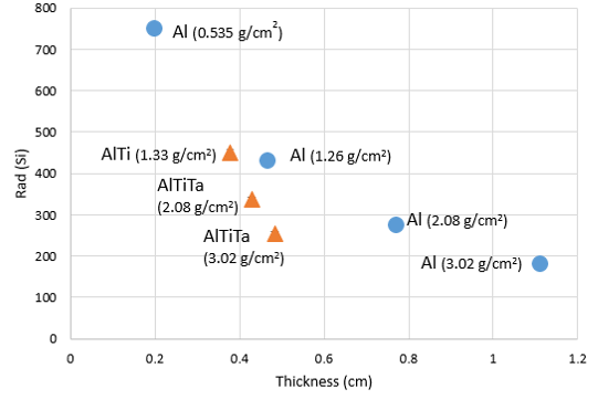
Z-shielding enables a low-volume shielding solution for CubeSat and SmallSat applications where reduced volume is important. AlTiTa, Z–shielding, at 2.08 g cm-2 reduces the dose from a SPE by approximately half when compared to a standard 0.2 cm aluminum structure (Figure 6.15). NASA has innovated “Methods of Making Z-Shielding” with patents in preparing different structural shielding approaches (87)(88)(89)(90), from metals to hybrid metal laminates and thin structural radiation shielding, to enable low-volume integrated solutions with CubeSats and SmallSats (91).
| Table 6-15: Shields-1 Experimental Total Ionizing Dose Measurements in PLEO | ||||
|---|---|---|---|---|
| Shielding | Areal Density (g/cm2) | Thickness (cm) | Trapped Belts TID Total (Rad (Si)/Year) | SPE King Sphere Model, (Rad (Si)) |
| Al | 0.535 | 0.198 | 1383+/-47 # | 750+/-5 |
| Al | 1.26 | 0.465 | 90.9 +/-2.7 (SL) | 432 +/- 7 |
| Al | 1.69 | 0.624 | 84.3 +/-2.5 (SL) | 345 +/- 9 |
| Al | 3.02 | 1.11 | 73.6 +/-3.2 (SL) | 183 +/- 11 |
| AlTi | 1.33 | 0.378 | 89.7 +/-2.7 (SL) | 451 +/- 6 |
| AlTiTa20 | 2.08 | 0.429 | 84.3 +/-2.5 (SL) | 338 +/- 6 |
| AlTiTa40 | 3.02 | 0.483 | 81.9 +/-3.4 (SL) 75.6+/-3.2 (Vault) | 253 +/- 6 |
| Shields-1 Experimental total ionizing dose measurements in PLEO in comparison to typical 0.20 cm aluminum shielding commercially available for CubeSats and SPE additional contributions to dose. Bold values Shields-1 experimental results. SL = Slab, Vault = Z-Shielding electronics enclosure. # sphere Space Environment Information System (SPENVIS) Multi-layered Shielding Simulation Software (MULASSIS) AP8 Min AE8 Max modeled results. SPE King Sphere Model SPENVIS MULASSIS modeled results. | ||||
6.5.4 Ad Hoc Shielding
There are two types of ad hoc shielding used on spacecraft: spot shielding, where a single board or component is covered in shield material (often conformally), and sector shielding, where only critical areas of the spacecraft have shielding enhancement. These two methods are often used in concert as necessary to further insulate particularly sensitive components without unnecessarily increasing the overall shield mass and/or volume. Ad hoc shielding is more efficient per unit mass than inherent mass shielding because it can be optimized for the spacecraft’s intended radiation environment while relaxing the structural constraints. The most recent methods include multi-layer shields with layer-unique elemental atomic numbers, which are layered advantageously (often in a low-high-low Z scheme), known as “graded-Z” shielding, and advanced low-Z polymer or composite mixtures doped with high-Z, metallic micro-particles. Low-Z elements are particularly capable of shielding protons and ions while generating little secondary radiation, whereas high-Z elements scatter electrons and photons much more efficiently. Neutron shielding is a unique problem, where optimal shield materials often depend on the particle energies involved. Commercial options include notably Tethers Unlimited’s VSRS system for small spacecraft, which was specifically designed to be manufactured under a 3D printed fused filament fabrication process for conformal coating applications (a method which optimizes volume and minimizes shield gaps).
6.5.5 Charge Dissipation Coating
The addition of conformal coatings over finished electronic boards is another method to mitigate electrostatic discharge in sensitive electronic environments. Arathane, polyurethane coating materials (92), and HumiSeal acrylic coatings (93) have been used to mitigate discharge and provide limited moisture protection for electronic boards. This simple protective coating over sensitive electronic boards helps support mission assurance and safety efforts. Charge dissipation films have decreased electrical resistances in comparison to standard electronics and have been described by NASA as coatings that have volume resistivities between 108 – 1012 ohm-cm. In comparison, typical conformal coatings have volume resistivities from 1012 – 1015 ohm-cm (50).
6.5.6 LUNA Innovations, Inc. XP Charge Dissipation Coating
The XP Charge Dissipation Coating has volume resistivities in the range of 108 – 1012 ohm-cm (Table 6-16) and is currently developing space heritage through the NASA MISSE 9 mission and Shields-1 (94). The XP Charge Dissipation Coatings were developed through the NASA SBIR program from 2010 to the present for extreme electron radiation environments, such as outer planets, medium-Earth, and geostationary orbits, to mitigate charging effects on electronic boards.
| Table 6-16: XP Charge Dissipation Coating and Commercial Conformal Coating Resistivity Comparisons | |
|---|---|
| Material | Volume Resistivity (Ohm-cm) |
| XP Charge Dissipation Coating | 108 – 1012, 4.7 x 10⁹ at 25°C |
| Arathane 5750 A/B | 9.3 X 10¹⁵ at 25°C, 2.0 X 10¹³ at 95°C |
| Humiseal 1B73 | 5.5 x 10¹⁴ Ohms (Insulation Resistance per MIL-I-46058C) |
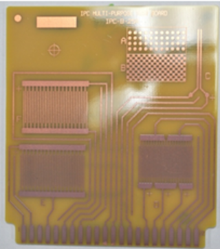
Compared to typical commercial conformal coatings, the LUNA XP Charge Dissipation Coating has reduced electrical resistance, which reduces surface charging risk on electronic boards. LUNA XP Coating (Figure 6.16) on an electronic board has transparency for visual parts inspection. For extreme radiation environments, a combination of radiation shielding and charge dissipation coating reduces the ionizing radiation that contributes to charging and provides a surface pathway for removing charge to ground (50).
6.6 Summary
This chapter has been updated with the current status of structures, materials, and mechanisms for small satellite missions. Additions include custom structure references addressing the dimensional and material requirements of integrating deployment systems, new mechanisms technology to reflect the ongoing growth in SmallSat mechanical devices, and more commercially procured deployable booms and larger CubeSat primary structures (12U and 16U), as well as the upcoming DiskSat structure. The radiation environment section, state-of-the-art radiation shielding, and charge dissipation materials have been updated. Reflecting the fast pace of development in additive manufacturing, a selection of available thermoplastics and resin-based materials suitable for different TRL levels has been detailed.
There has been a high focus on deployment mechanisms with respect to lightweighting and reliability. Small spacecraft subsystems related to antenna booms, gravity gradients, stabilization, sensors, sails, and solar panels are some examples. These technologies are gaining space heritage through operations and are increasingly included in mission planning. The growth of these deployment mechanisms increases the capabilities of SmallSat technology and will be a continued focus in the next edition of this report.
For feedback solicitation, please email: arc-sst-soa@mail.nasa.gov. Please include a business email so someone may contact you further
References
- Space Weather Prediction Center. Solar Cycle 25 Forecast Update. December 19, 2019. [Online] Available at: https://www.swpc.noaa.gov/news/solar-cycle-25-forecast-update
- R. Welle, C. Venturini, D. Hinkley, J. Gangestad, S. Grasso, A. Muszynski, R. Hunter, C. Frost, D. Mayer, and C. Baker, “DiskSat: Demonstration Mission for a Two-Dimensional Satellite Architecture,” Proceedings of the AIAA/USU Conference on Small Satellites, Out of this World!, SSC22-VIII-01, 2022.
- R. Hevner, W. Holemans, J. Puig-Suari, and R. Twiggs. “An Advanced Standard for CubeSat.” 2003. 25th Annual AIAA/USU Conference for Small Satellites.
- NASA Goddard Technical Standards, “GSFC General Environmental Verification Standard (GEVS) for GSFC Flight Programs and Projects,” GSFC-STD-7000B, 28 April 2021.
- Tianyuan Ye et al. “Review of Deployable Mechanism Test Technologies Oriented Towards Deep Space Exploration,” 2021 IOP Conference Ser.: Material Science Engineering. 1043 052022
- NASA. “Deployable Composite Booms (DCB).” August 26, 2020. [Online] Accessed May 18, 2021. Available at: https://www.nasa.gov/centers-and-facilities/langley/deployable-composite-booms-dcb/
- NASA. “Advanced Composite Solar Sail System: Using Sunlight to Power Deep Space Exploration.” [Online] June 23, 2021. Accessed October 2022. Available at: https://www.nasa.gov/directorates/spacetech/small_spacecraft/ACS3/
- Brigham Young University. “Origami-Inspired Mechanisms Explained.” 2022. Accessed October 2022. [Online] Available at: https://www.compliantmechanisms.byu.edu/about-origami-mechanisms
- J. Reveles et al. “In-Orbit Performance of AstroTube: AlSat Nano’s Low Mass Deployable Composite Boom Payload.” Proceedings of the AIAA/USU 31st Annual AIAA/USU Conference of Small Satellites, Logan, UT, 2017.
- B.L. Davis, W.H. Francis, J.A. Goff, M.C. Cross, and D.J. Copel. “Big Deployables in Small Satellites,” Proceedings of the AIAA/USU Conference on Small Satellites, The Commerce of Small Satellites, SSC12-XII-1, 2014.
- NASA. “In-space Servicing, Assembly, and Manufacturing (ISAM) State of Play,” 2023 Edition. Available at: https://www.nasa.gov/wp-content/uploads/2023/10/isam-state-of-play-2023.pdf
- A. Nance and M. Thibault. “CubeSat-scale Robotic Arms in Space,” US Naval Academy. CubeSat Developer’s Workshop Conference 2023. Available at: http://mstl.atl.calpoly.edu/~workshop/archive/2023/presentations/2023_Day2_Session6_ThibaultNance.pdf
- NASA Reliability and Maintainability (R&M) Standard for Spaceflight and Support Systems, NASA-STD-8729.1A – 2017-06-13.
- Raja Pandi Perumal, Holger Voos, Florio Dalla Vedova, Hubert Moser. “Small Satellite Reliability, A Decade in Review,” SSC21-WKIII-02, 35th Annual Small Satellite Conference, Logan, UT, 2021, p.12.
- Thomas P. Sarafin Ed, Spacecraft Structures and Mechanisms. Damon D. Phinney and William R. Britton, Ch.19 “Developing Mechanisms,” pp.665-734.
- NASA Standard 5017B, “Design and Development Requirements for Mechanisms,” 12/06/2022, p. 117
- MIL-A-83577B (USAF), 2/1/1988, “Assemblies, Moving Mechanical, for Space and Launch Vehicles, General Specifications,” p.70.
- MIL-PRF-8625F w/ amendement 2, 11/23/2020, “Anodic Coatings for Aluminum and Aluminum Alloy,” p.20.
- NASA. Technical Handbook, “Mitigating In-Space Charging Effects – A Guideline.” NASA-HDBK-4002A. October 19, 2017.
- ColorFabb. “PLA/PHA.” Technical Datasheet, April 8, 2020. [Online] Available at: https://colorfabb.com/media/datasheets/tds/colorfabb/TDS_E_ColorFabb_PLA_PHA.pd
- Stratasys. “PLA: Economy Thermoplastic for Stratasys F123 Series Printers.” Technical Datasheet 2018. Available at: https://stratasysstorage01.file.core.windows.net/ssys-websites-files-prod/Public1/Materials/FDM/PLA/PLA%20-%20EN%20Data%20Sheet%20FDM%20Material.pdf?sv=2017-04-17&sr=f&sig=colFyWKHIkaQ9GUZsyg0%2FFwD%2Fllpuft2a2SR%2FYKqFEg%3D&st=2022-11-27T23%3A00%3A27Z&se=2023-11-28T23%3A00%3A27Z&sp=rwl
- NASA. “What is KickSat-2?” June 3, 2019. Accessed July 12, 2021. [Online] Available at: https://www.nasa.gov/ames/kicksat
- Taulman3D. “Alloy 910 Specifications.” Accessed July 12, 2021. [Online] Available at: https://taulman3d.com/alloy-910-spec.html
- Taulman3D. “Alloy 680 Specifications.” Accessed July 12, 2021. [Online] Available at: https://taulman3d.com/nylon-680-spec.html
- Markforged. “Onyx ESD™.” Technical Datasheet. Accessed July 12, 2021. [Online] Available at: https://markforged.com/materials/plastics/onyx-esd
- 3DXTech Additive Manufacturing. “CARBONX HTN+CF [HIGH TEMP CF NYLON].” Accessed July 12, 2021. [Online] Available at: https://www.3dxtech.com/product/carbonx-htn-cf/
- Statasys. “Nylon 12.” Accessed July 12, 2021. [Online] Available at: https://www.stratasys.com/materials/search/fdm-nylon-12
- Prusa Polymers. “Prusament PC Blend.” Technical Datasheet. [Online] Available at: https://prusament.com/media/2022/10/PCBlendCF_Prusament_TDS_2022_16_EN.pdf
- Stratasys. “PC (Polycarbonate): FDM Thermoplastic Filament.” Technical Datasheet, Accessed July 12, 2021. [Online] Available at: https://www.stratasys.com/-/media/files/material-spec-sheets/mds_fdm_pc_0920a.pdf
- CRP Technology. “High performance composite materials for SLS.” 2018. [Online] Available at: https://www.windform.com/top-line/#strength
- CRP Technology. “Windform 3D Printing materials launch into Orbit on KySat-2.” Accessed July 12, 2021. [Online]. Available at: https://www.crp-usa.net/windform-3d-printing-materials-launch-orbit kysat-2/
- CRP Technology. “Winform XT 2.0” Technical Datasheet.Accessed July 12, 2021. [Online] Available at: http://www.windform.com/windform-xt-2-0.html
- CRP Technology. “Winform RS” Technical Datasheet. Accessed July 12, 2021. [Online] Available at: http://www.windform.com/windform-rs.html
- 3DXTech Additive Manufacturing. “3DXSTAT™ ESD-Ultem™ 3D Printing Filament.” Technical Datasheet. [Online] Available at: https://www.3dxtech.com/wp-content/uploads/2020/11/ESD_Ultem_v3.pdf
- Stratasys. “ULTEM 1010 Resin.” Accessed July 12, 2021. [Online] Available at: https://www.stratasys.com/en/materials/materials-catalog/fdm-materials/ultem-1010/
- Stratasys. “ULTEM 9085 Resin.” Accessed July 12, 2021. [Online] Available at: https://www.stratasys.com/en/materials/materials-catalog/fdm-materials/ultem-9085/
- Zortrax. “Aerospace-Grade Flame-Retardant Filament.” Technical Datasheet, October 9, 2020, Updated June 22, 2021. [Online] Available at: https://cf.zortrax.com/wp-content/uploads/2020/10/Z-PEI_9085_Technical_Data_Sheet_eng.pdf
- TechBriefs. “Plastic Components Ride Juno Spacecraft to Jupiter.” August 1, 2012. [Online] Available at: https://www.techbriefs.com/component/content/article/tb/pub/features/applications/14486
- 3DXTech Additive Manufacturing. “3DXSTAT™ ESD-PEEK 3D Printing Filament.” [Online] Available at: https://www.3dxtech.com/product/3dxstat-esd-peek/
- Stratasys. “Antero 840CN03 High-Performance PEKK-Based ESD Thermoplastic.” [Online] Accessed July 12, 2021. Available at: https://www.stratasys.com/materials/search/antero-840cn03
- Zortrax. “Z-PEEL.” Accessed July 12, 2021. [Online] Available at: https://zortrax.com/filaments/z-peek/
- 3D Systems Inc. “Accura Bluestone Technical Data.” September 2020. [Online] Available at: https://www.3dsystems.com/sites/default/files/2020-11/3d-systems-accura-bluestone-datasheet-usen-2020-09-15-a-print.pdf
- 3D Systems, Inc. “VisiJet M2S-HT250 (MJP).” Accessed June 24, 2021. [Online] Available at: https://www.3dsystems.com/materials/visijet-m2s-ht250
- Henkel Corporation, Loctite. “IND402TM: PhotoElastic A70 High Rebound Black.” Technical Datasheet. March 22, 2022. [Online] Available at: https://www.loctiteam.com/wp-content/uploads/2022/03/Loctite-3D-IND402-A70-High-Rebound-2022_03_22.pdf
- Stratasys. “LOCTITE ® 3D 3843 High Toughness by Henkel.” [Online] Available at: https://www.stratasys.com/en/materials/materials-catalog/p3-materials/loctite-3d-3843-high-toughness/
- J.R. Wertz and W.J. Larson. “Space Mission Analysis and Design, Third Edition.” Space Technology Library, Space Technology Series, Hawthorne, CA: Microcosm Press and New York: Springer, 1999, p.976.
- D. Hastings and H. Garrett, “Spacecraft Environment Interactions.” New York, NY: Cambridge University Press, 1996, p.292.
- M. Langer and M. Boumeester. “Reliability of CubeSats – Statistical Data, Developers’ Beliefs and the Way Forward,” 30th Annual AIAA/USU Conference on Small Satellites, August 2016, Logan, UT, SSC16-X-2, 1-12.
- NASA Preferred Reliability Series PD 1258, “Space Radiation Effects on Electronic Components in Low Earth Orbit,” August 1996.
- D.L. Thomsen. “Shields-1 Preliminary Radiation Shielding Dosimetry in Polar Low Earth Orbit,” Committee on Space Research (COSPAR), Small Satellites for Sustainable Science and Development, Herzliya, Israel, 7 November 2019.
- Vampola, A. L. “The Space Particle Environment,” NASA/SDIO Space Environmental Effects on Materials Workshop, NASA Conference Proceedings 3035, part 2, NASA Langley Research Center, Hampton, VA June 28 – July 1, 1988, pg. 367.
- NASA Preferred Reliability Series PD 1260, “Radiation Design Margin Requirement,” May 1996.
- D.M. Sawyer and J.I. Vette, “AP-8 Trapped Proton Environment for Solar Maximum and Solar Minimum.” NSSDC/WDC-A-R&S 76-06, 1976.
- J.I. Vette. “The AE-8 Trapped Electron Model Environment.” NSSDC/WDC-A-R&S 91-24, 1991a.
- D.L. Thomsen III, W. Kim, and J.W. Cutler. “Shields-1, A SmallSat Radiation Shielding Technology Demonstration,” 29th AIAA/USU Conference on Small Satellites, SSC15-XII-9, August 2015.
- D.L. Thomsen III, R.J. Cano, B.J. Jensen, S.J. Hales, and J.A. Alexa. “Methods of Making Z-Shielding.” U.S. Patent No. 8,661,653, 4 March 2014.
- U.S. Patent No. 10,039,217, July 31, 2018, “Methods of Making Z-Shielding.” D.L. Thomsen III, R.J. Cano, B.J. Jensen, S.J. Hales, and J.A. Alexa.
- D.L. Thomsen III. “Method of Making Thin Atomic (Z) Grade Shields.” U.S. Patent No. 10,600,52212, March 24, 2020.
- D.L. Thomsen III, S.N. Sankaran, and J.A. Alexa. “Atomic Number (Z) Grade Shielding Materials and Methods of Making Atomic Number (Z) Grade Shielding.” U.S. Patent No. 10,919,650, February 16, 2021.
- D.L. Thomsen III and W.R. Girard. “Method of Making Atomic Number (Z) Grade Small SAT Radiation Shielding Vault.” U.S. Patent No. 11,043,311, June 22, 2021.
- Arathane. [Online] Available at: https://apps.huntsmanservice.com/WebFolder/ui/browse.do?pFileName=/opt/TDS/Huntsman%20Advanced%20Materials/English%20US/Long/Arathane%205750%20AB_LV_US_e.pdf
- Chase Electronic Coatings. “HumiSeal® 1B73 Acrylic Conformal Coating Technical Data Sheet.” [Online] Available at: https://chasecorp.com/humiseal1/wp-content/uploads/sites/12/2018/10/1B73-TDS.pdf
- LUNA. “Luna coating provides radiation protection in space.” [Online] February 2, 2018. Accessed June 28, 2020. Available at: https://lunainc.com/blog/luna-coating-provides-radiation-protection-space