


Chapter Contents
- Chapter Glossary
- 7.1 Introduction
- 7.2 State-of-the-Art – Passive Systems
- 7.2.2 Thermal Straps
- 7.2.3 Thermal Contact Conductance and Bolted Joint Conductance
- 7.2.4 Thermal Interface Materials and Conductive Gaskets
- 7.2.5 Sunshields
- 7.2.6 Thermal Louvers
- 7.2.7 Deployable Radiators
- 7.2.8 Heat Pipes
- 7.2.9 Phase Change Materials and Thermal Storage Units
- 7.2.10 Thermal Switches
- 7.2.11 Multifunctional Thermal Structures
- 7.3 State-of-the-Art – Active Systems
- 7.4 Summary
- References
Chapter Glossary
| (APG) | Annealed Pyrolytic Graphite |
| (ATA) | Active Thermal Architecture |
| (BIRD) | Bi-Spectral Infrared Detection |
| (BOL) | Beginning of Life |
| (EOL) | End of Life |
| (ESPA) | EELV Secondary Payload Adapter |
| (FEP) | Fluorinated Ethylene Propylene |
| (FETS) | Folding Elastic Thermal Surface |
| (FOX) | Flat-Plate Heat Pipe On-Orbit Experiment |
| (GFTS) | Graphite Fiber Thermal Straps |
| (GSFC) | Goddard Space Flight Center |
| (HEC) | High Efficiency Cooler |
| (HX) | Heat Exchanger |
| (IR) | Infrared |
| (ISS) | International Space Station |
| (MLI) | Multi-Layer Insulation |
| (MPFL) | Mechanically Pumped Fluid Loop |
| (MWIR) | Midwave Infrared |
| (NLAS) | Nanosatellite Launch Adapter System |
| (OHP) | Oscillating Heat Pipe |
| (PCM) | Phase Change Materials |
| (PID) | Proportional–Integral–Derivative (control algorithm) |
| (PFL) | Pumped Fluid Loop |
| (PGF) | Pyrovo Pyrolytic Graphite Film |
| (PGS) | Pyrolytic Graphite Sheets |
| (PRISM) | Portable Remote Imaging Spectrometer |
| (qalbedo) | Solar heating reflected by the planet |
| (Qgen) | Heat generated by the spacecraft |
| (Qout,rad) | Heat emitted via radiation |
| (qplanetshine) | IR heating from the planet |
| (qsolar) | Solar heating |
| (Qstored) | Heat stored by the spacecraft |
| (SDL) | Space Dynamics Laboratory |
| (SI) | International System of Units |
| (SPOT) | Standard Passive Orbital Thermal-Control |
| (SST) | Small Satellite Technology |
| (TAFTS) | Two Arm Flexible Thermal Strap |
| (TEC) | Thermoelectric Coolers |
| (TMT) | Thermal Management Technologies |
| (TRL) | Technology Readiness Level |
| (TSU) | Thermal Storage Unit |
| (UAM) | Ultrasonic additive manufacturing |
| (VDA) | Vacuum Deposited Aluminum |
7.1 Introduction
All spacecraft components have a range of allowable temperatures that must be maintained to meet both survival and operational requirements during all mission phases. Spacecraft temperatures are determined by how much heat is absorbed, stored, generated, and dissipated by the spacecraft. Figure 7.1 shows a simplified overview of heat exchange from a satellite orbiting Earth, but the heating principles apply to any planet or body a spacecraft orbits.
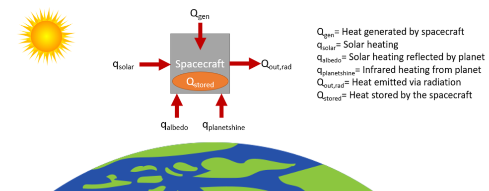
The heat exchange depends on several factors listed below. Solar absorptivity and infrared (IR) emissivity are surface optical properties referenced below and described further in Section 7.2.1: Sprayable Thermal Control Coatings, Tapes, and MLI. Thermal control of a spacecraft is achieved by balancing the energy flows as shown in Equation 1:
qsolar + qalbedo + qplanetshine + Qgen = Qstored + Qout,rad (1)
- Qgen (heat generated by the spacecraft) depends on the power dissipation of spacecraft components.
- The amount of qsolar (solar heating) absorbed by the spacecraft depends on the solar flux, which is determined by the distance to the Sun, the surface area viewing the Sun (view factor), and the solar absorptivity of that surface.
- The amount of qalbedo (solar heating reflected by the planet) absorbed by the spacecraft depends on the planetary body, the surface area viewing the planet (view factor), and the solar absorptivity of that surface.
- The amount of qplanetshine (IR heating from the planet) absorbed by the spacecraft depends on the planetary body, the surface area viewing the planet (view factor), and the IR emissivity of that surface.
- Qout,rad (heat emitted via radiation) includes the surface area designated as radiator space, the IR emissivity of the surface, and the difference in temperature between the spacecraft radiator and the heat sink to which it is dissipating, typically and most effectively to deep space. Qout,rad also includes heat lost through insulation or other surfaces not specifically intended to function as radiators (i.e., parasitic losses).
- Qstored (heat stored by the spacecraft) is based on the thermal capacitance of the spacecraft.
Temperatures are regulated with passive and/or active thermal management technologies and design methods. Many of the same thermal management methods used on larger spacecraft are also applicable to SmallSats, and given the increased interest in small spacecraft over the last decade, some spacecraft thermal control technologies have been miniaturized or otherwise adapted to apply to SmallSats. Thermal control methods and technologies as applied to large spacecraft are considered state-of-the-art for the purposes of this review, but may have a Technology Readiness Level (TRL) value less than 9 for small spacecraft applications.
Challenges of designing thermal control systems for SmallSats stem from several intrinsic properties, summarized in Table 7-1. Due to the small size and volume limitations inside the deployer or around deployables, there is often no room for multi-layer insulation (MLI) on CubeSats. The thermal solution must be worked out as a coatings problem, exposing the CubeSat to more pronounced transient thermal behaviors.
| Table 7‑1: SmallSat Thermal Control Challenges | |
|---|---|
| SmallSat Property | Challenge |
| Low thermal mass | The spacecraft is more reactive to changing thermal environments. |
| Limited external surface area | There is less real estate to be allocated to solar cells, designated radiator area, and/or viewports required for science instruments. |
| Limited volume | There is less space for electronic components, science instruments, and thermal control hardware. Components can be more thermally coupled, and it can be harder to isolate different thermal zones. |
| Limited power | There is less power available for powered thermal control technology. |
| Power Density | There is a big challenge to dissipate power as electronics are stacked close to each other, sometimes with no direct path to radiator. |
| MLI Edge Effects | MLI can “short” along the edges resulting in degraded performance, not specific to SmallSats but more of a general spacecraft issue. |
The information described in this section is not exhaustive but instead provides an overview of current state-of-the-art thermal technologies and their level of development. The list of organizations/companies in this chapter is not all-encompassing and does not constitute an endorsement by NASA. There is no intention to mention certain companies and omit others based on their technologies or their relationship with NASA. The performance advertised may differ from actual performance because the information has not been independently verified by NASA subject matter experts and relies on information provided directly by manufacturers or from publicly available data. It should be noted that TRL designations may vary depending on the payload, mission requirements, reliability considerations, and/or the environment in which performance was demonstrated. Readers are highly encouraged to contact companies for further information regarding the performance and TRL of the described technologies.
7.2 State-of-the-Art – Passive Systems
Passive thermal control maintains component temperatures without using electrically powered equipment. Passive systems are typically associated with low cost, volume, weight, and risk, and are advantageous for spacecraft with limited mass, volume, and power, like SmallSats and especially CubeSats. MLI, coatings, surface finishes, interface conductance, heat pipes, sunshades, thermal straps, interface materials, and louvers are some examples of passive thermal control technologies.
In addition to passive thermal control technologies, structural and electrical design methods also contribute to passively managing the thermal environment. These design methods include the following:
- Material selection
- Structural component materials are chosen based on the needed heat transfer through the structure. A high or low thermal conductivity may be more advantageous depending on the application.
- Spacecraft orientation
- If orientation is not dictated by science objectives, changing the orientation of the spacecraft can help regulate temperatures.
- Changing orientation may only be needed during certain mission phases, such as science operations, if larger amounts of heat are dissipated.
- This method is often used in conjunction with other thermal control methods, such as orienting the spacecraft so that the radiator area can face deep space.
- Thermal interfaces:
- Definition of the thermal contact between components through specific mounting methods can thermally isolate components or allow more heat to be transferred to a structural element (or radiator area) as needed. For example:
- Heat transfer can be reduced by mounting a component through multiple stacked washers with low thermal conductivity (i.e., thermal isolation).
- Heat transfer can be increased by mounting components with more fasteners (if applicable) and can be further increased by using thermal interface materials between a component and its mounting surface.
- Definition of the thermal contact between components through specific mounting methods can thermally isolate components or allow more heat to be transferred to a structural element (or radiator area) as needed. For example:
- Circuit board design considerations:
- Copper layers within each board can be increased in number or thickness to conduct heat away from electrical components through the boards to their structural connection points.
- Circuit boards can be mounted to increase heat transfer away from the boards to the structure, such as by mounting with wedge locks.
Below provides a description of current passive thermal control technology as applied to SmallSats. One key factor to consider when choosing thermal control technology, both passive and active, is the temperature limit of the technology itself. The goal is to use the appropriate technology to maintain the temperatures of spacecraft components within their limits, but the technology used to achieve this also has limits. It is recommended to verify that the technology used is applicable to the given design not only with respect to its needed function, but also with respect to the environment (temperature limits).
| Table 7‑2: SmallSat Passive Thermal Technologies | |
|---|---|
| Passive Technology | Description |
| Sprayable Thermal Control Coatings | Specialized liquid coatings applied to the spacecraft surfaces to manage and regulate the ratio of absorptivity and emissivity for optimal energy balance and thermal performance. |
| Films, Tapes, and MLI | Materials used to modify spacecraft surface properties to manage and regulate temperature. |
| Thermal Straps | Provide a conductive link between a heat source and thermal sink to conductively transfer heat. |
| Thermal Contact Conductance and Bolted Joint Conductance | Heat transfer by “contact” conductance between two surfaces pressed together by uniform pressure can be varied by using interface filler materials and conductive gaskets. |
| Sunshields | Deployed material that reduces the amount of incident solar flux on a spacecraft. |
| Thermal Louvers | Controls heat transfer between spacecraft surfaces. |
| Deployable Radiators | Dedicated surface for dissipating excess heat via radiative heat transfer. |
| Phase Change Materials | Energy is absorbed as material within a metal compartment changes phase because of exposure to a heat source. |
| Mechanical Thermostat | An electromechanical device which controls the flow of electrical current in response to temperature change. |
7.2.1 Sprayable Thermal Control Coatings, Tapes, and MLI
In a vacuum, heat is transferred only by radiation and conduction with no convection. The internal environment of a fully enclosed small satellite is usually dominated by conductive heat transfer, while heat transfer to and from the outside environment is driven via thermal radiation. Many missions with electrical surface resistivity requirements use coatings with these properties to address surface charging concerns (this also applies to MLI). For SmallSat missions where extensive use of MLI is not practical (see MLI paragraph on page 207), a combination of several different coatings is needed to achieve optimal energy balance and thermal performance. There are also coatings that better approximate the use of MLI by being relatively low emissivity (such as 0.25) with a lower alpha (0.1) so they don’t overheat in the sun. These are colloquially known as tailorable emittance coatings, which involve some oxide depositions starting with a vacuum deposited aluminum (VDA) base to increase emissivity while keeping the solar absorptivity (alpha) low.
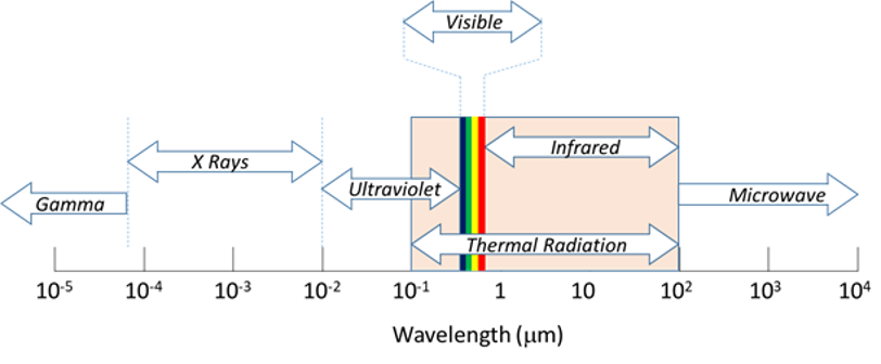
The thermal radiation band of the electromagnetic spectrum is between 0.1 and 100 µm in wavelength, as shown in Figure 7.2. Outside of the thermal radiation waveband, electromagnetic energy generally passes through objects or has very little heat energy under practical conditions. Thermal analyses are typically conducted using a two-waveband absorptance model that subdivides the thermal energy spectrum into solar (< 3 µm) and IR (> 3 µm) wavelengths. Thermal radiation heat transfer is controlled by using materials that have specific optical surface properties, namely solar absorptivity and IR emissivity. Solar absorptivity governs how much incident heating from solar radiation a spacecraft absorbs, while IR emissivity determines how much heat a spacecraft emits to space, relative to a perfect blackbody emitter, and what fraction of thermal radiation from IR sources (e.g., the Earth, Moon, or any particularly hot spacecraft components) are absorbed by that spacecraft surface.
The surface properties of a spacecraft can be modified by adding specialized paints, coatings, surface finishes, or adhesive tapes, depending on the needs of the spacecraft. For example, matte black paint has a high solar absorptivity and high IR emissivity for surfaces required to absorb a high percentage of solar heating and emit a high percentage of spacecraft heat. Alternatively, matte white paint has a low solar absorptivity and high IR emissivity (1) for surfaces required to absorb a low percentage of solar heating and emit a high percentage of spacecraft heat (e.g., radiator). Second-surface silver Fluorinated Ethylene Propylene (FEP) tapes offer excellent performance as radiator coatings, reflecting incident solar energy (low solar absorptivity) while simultaneously emitting spacecraft thermal energy efficiently (high IR emissivity). The selection between paints, coatings, and tapes depends on the specific application. Tape is typically easy to apply and remove, is comparatively inexpensive, and often has a longer usable lifetime than paint. Tape can also be added later in the assembly process if changes to thermal control are required after the spacecraft has already begun assembly. Some tapes, however, must be handled carefully to maintain optical properties and can be difficult to bond properly to curved surfaces.
While optical films and tapes may have solar absorptivities and IR emissivities very close to the datasheet values as received from the manufacturer, these two values will change throughout the mission. Coatings will darken due to atomic oxygen bombardment (low Earth orbit), UV light (high Earth orbit, GEO, and beyond), and other cosmic rays. This will increase the solar absorptance values, some quite substantially. The longer the mission duration, the more the optical coating properties will change. It is important that the thermal engineer takes this into consideration; thermal performance at the beginning-of-life (BOL) of a tape/film may not be the same at its end-of-life (EOL). Thermal analysis should take this into consideration and appropriately bias the optical property values in the thermal models to account for this degradation. BOL measurements from the datasheets (used for cold biased conditions) should not be used for EOL modeling, which represents hot-biased conditions.
Coatings and paints must often be applied earlier in the assembly process but can more easily cover non-flat surfaces. However, some paints, such as Parker-Lord’s Aeroglaze 306/307, are expensive and require extensive and highly specialized processes to apply. Different options may also have different temperature limits. All these factors must be considered with respect to the application when selecting the final solution. Table 7-3 has a list of non-exhaustive sprayable thermal control coatings that include application difficulty and specific notes on some of the products.
One example, BioSentinel, a 6U spacecraft that launched as a secondary payload on the Artemis I mission in 2022, made extensive use of Sheldahl metallized tape coatings and second-surface silvered FEP tapes to control its external thermal radiative properties and overall energy balance (2). Another example, Picard, a 150 kg SmallSat, used white paint on the Sun pointing face to reduce the amount of solar flux absorbed and lower temperatures. For most small spacecraft projects to date, adhesive tapes, such as silver FEP, or other standard surface finishes (e.g., polishing, anodize, alodine) have been the preferred choices.
| Table 7-3: Sprayable Thermal Control Coatings | |||||
| Manufacturer | Product | Color | Cost | Difficulty to Apply* | Notes: |
| Socomore | Z306 Polyurethane | Black | $ | 1 | |
| Z307 Polyurethane | Black | $$ | 1 | ||
| A276 Polyurethane | White | $ | 1 | Not UV stable | |
| Huntington Ingalls Industries (formerly Alion and IITRI) | Z93P Silicate | White | $$ | 3 | ** |
| Z93-C55 Silicate | White | $$$ | 4 | Thickness control paramount ** | |
| S13GP:6N/LO-1 Silicone | White | $$$ | 1 | Dedicated equipment/cross contamination | |
| AZ Technology | AZ-93 Silicate | White | $$ | 3 | ** |
| AZ2000 Silicate | Off-white | $$$ | 4 | May require specialty, epoxy primer ** | |
| AZW/LA-II Silicate | White | $$$$ | 5 | Thickness control paramount ** | |
| *1 not difficult, 5 extremely **All silicates require temperature and RH control | |||||
A MLI blanket is typically comprised of multiple inner layers of a thin material with low IR emissivity (usually 10 to 20 layers) and a durable outer layer. The amount of radiative heat transfer allowed is limited by the many layers of reflectors. The low IR emissivity layers are either embossed or alternated with thin netting to limit conduction through the layers. Perforations may be added to allow the MLI to vent trapped gas once arriving on-orbit, although this can also be achieved via edge venting. MLI is used as a thermal radiation barrier to both protect spacecraft from incoming solar and IR flux, and to prevent undesired radiative heat dissipation to space. It is commonly used to maintain temperature ranges for components in-orbit.
MLI is delicate and performance drops drastically if compressed (causing a thermally conductive “short circuit”), so it should be used with caution or avoided altogether on the exterior of small satellites that fit into a deployer (e.g., P-POD, NLAS). MLI blankets can also pose a potential snagging hazard in these tight-fitting, pusher-spring style deployers. Additionally, MLI blankets tend to drop efficiency as size decreases because heat transfer through the blanket increases closer to the blanket edges, and the specific attachment method has a large impact on performance because attachment to the spacecraft creates a heat path. Due to these challenges, MLI generally does not perform as well on small spacecraft (more specifically CubeSat form factors) as on larger spacecraft. Surface coatings are typically less delicate and more appropriate for the exterior of a small spacecraft that will be deployed from a dispenser. Internal MLI blankets that do not receive direct solar thermal radiation can often be replaced by a variety of low emissivity tapes or coatings that perform equally well in that context, using less volume and at a potentially lower cost.
| Table 7-4: Films, Tapes and MLI | ||
|---|---|---|
| Manufacturer | Film Product | Typical Solar Absorptivity BOL |
| Astral Technologies Unlimited | StaMet/100XC Kapton | 0.5 |
| StaMet/275XC Kapton | 0.56 | |
| Astral Technologies Unlimited Multek/Sheldahl | 0.010″ FEP/Ag/Inconel | 0.08 |
| 0.005″ FEP/Ag/Inconel | 0.07 | |
| ITO/0.010″ FEP/Ag/Inconel, perforated | 0.09 | |
| ITO/0.005″ FEP/Ag/Inconel, perforated | 0.08 | |
| Germanium/100XC Kapton | 0.55 | |
| Dunmore Multek/Sheldahl | VDA/200HN/PSA | 0.08 |
| 200HN/VDA/PSA | 0.41 | |
| 100HN/VDA/PSA | 0.38 | |
| VDG/200HN/PSA | 0.2 | |
| NASA GSFC | GSFC Silver Composite Coating/ 200HN Kapton | 0.1 |
| GSFC Aluminum Composite Coating/ 200HN Kapton | 0.14 | |
| GSFC Aluminum Composite Coating/ 100XC Kapton | 0.2 | |
| GSFC Aluminum Composite Coating/ 275XC Kapton | 0.28 | |
| GSFC Tailorable Emittance Coating/ 200HN Kapton | 0.14 | |
| Thales | Optical Solar Reflector CMX 0.005″ | 0.08 |
7.2.2 Thermal Straps
A thermal strap is a flexible, thermally conductive link added between a heat source and sink to conductively transfer heat. They are often used between high heat dissipating chips or components and a chassis wall or other radiator surface. Their flexibility prevents the addition of structural loads. Thermal straps can be made of metal, traditionally copper or aluminum, or high conductivity carbon materials, such as graphite. They can be formed of multiple foil sheets or wound cables (also referred to as ropes and braids), with end blocks at each end to hold the sheets/cables in place and to mount or otherwise attach to the needed surfaces. Straps with more than two end blocks and multiple material combinations can also be produced and have been used on large spacecraft. Advances in thermal straps are being developed to further increase heat transfer capability and custom thermal straps are now commonly fabricated and tested using graphite material due to improved thermal conductivity.
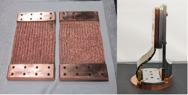
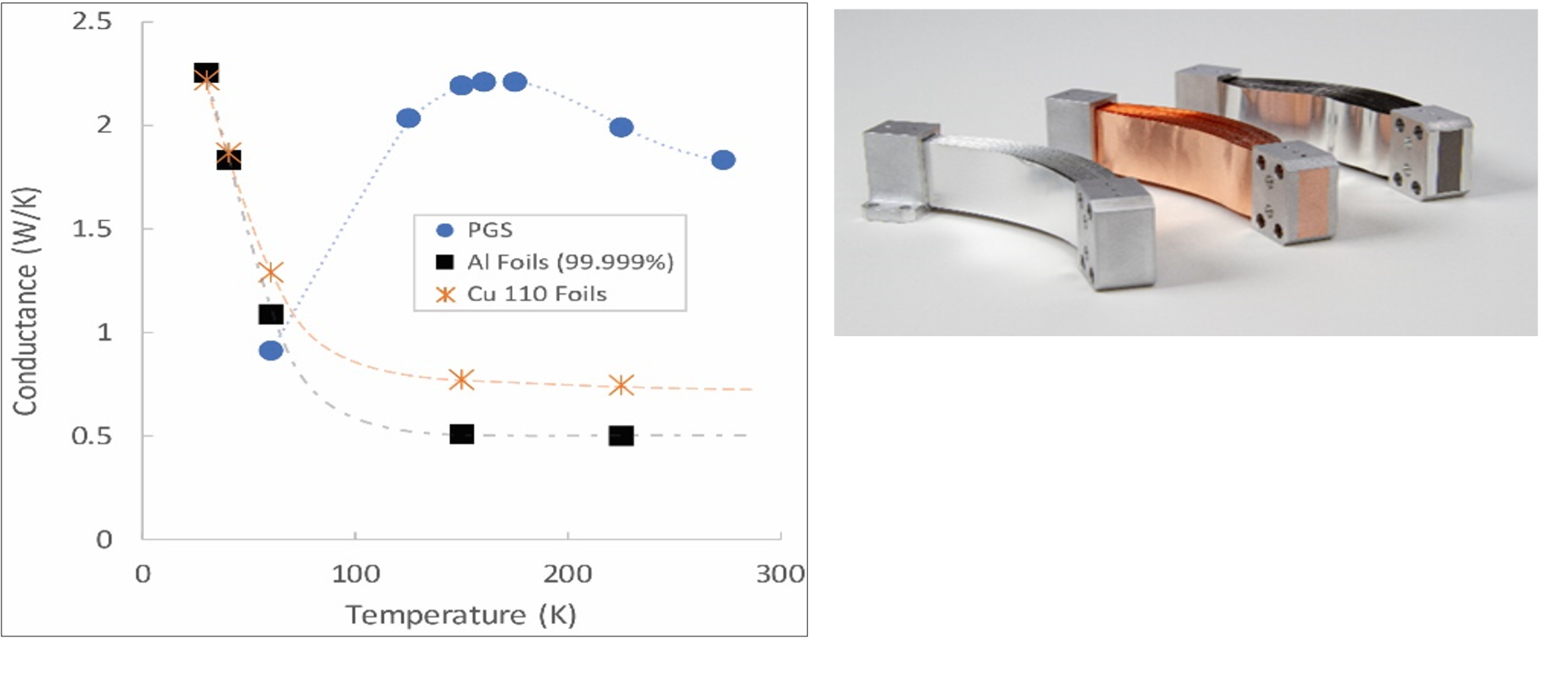
Space Dynamics Laboratory (SDL) developed solderless, flexible thermal straps without solder, epoxy, or other filler materials. Figure 7.4 shows a comparison of the as-tested conductance for the same strap geometry fabricated with three different foil materials: aluminum, copper, and pyrolytic graphite sheets (PGS), demonstrating that PGS increases the overall thermal conductivity. SDL supplied Utah State University with a PGS strap for the Active Thermal Architecture (ATA) project sponsored by the Small Spacecraft & Distributed Systems (SSDS, formally Small Spacecraft Technology) program. A follow-on to this ATA project is referenced in the Cryocooler section. Boyd Corporation has designed thermal straps using their patented K-core technology that has an annealed pyrolytic graphite (APG) core within an encapsulating structure (4). Technology Applications, Inc. has specialized in testing and developing Graphite Fiber Thermal Straps (GFTS), with flight heritage primarily on larger spacecraft missions (Orion and SPICE) (5). The Pyrovo Pyrolytic Graphite Film (PGF) thermal straps developed by Thermotive have flown in optical cooling applications for high altitude cameras and avionics on larger spacecraft, on JPL’s ASTERIA CubeSat in 2017, and on the Mars 2020 rover mission (6).
| Table 7‑5: Thermal Straps | ||
|---|---|---|
| Manufacturer | Product | Material |
| Technology Applications, Inc. | Copper Cable | Copper |
| Copper Foil | Copper | |
| Aluminum Foil | Aluminum 1100 | |
| PGL | Pyro Graphite | |
| GFTS | Graphite Fiber | |
| Thermotive | Copper Foil | Copper |
| Aluminum Foil | Aluminum 1100 | |
| Pyrovo | Pyro Graphite Film | |
| Space Dynamics Laboratory | PGS | Pyrolytic Graphite Sheet |
| Aluminum Foil | Aluminum 99.999% and 1235 | |
| Copper Foil | Copper 101 and 110 | |
| Copper Braid | Copper Braid | |
| Redwire Space | Q-Strap | High-k graphite material |
| Thermal Management Technologies | TMT010-200 Series | Copper Foil |
| TMT010-300 Series | Copper Braid (small) | |
| TMT010-400 Series | Copper Braid (large) | |
| Customized | Copper braid or foil or using aluminum foil | |
| Boyd Corporation | k-Core Graphite-Encapsulated | Pyrolytic graphite |
7.2.3 Thermal Contact Conductance and Bolted Joint Conductance
Two surfaces pressed together by uniform pressure will transfer heat via thermal contact conductance. This conductance value is a product of the heat transfer coefficient and the effective contact surface area. The heat transfer between such interfaces can be varied by using thermal interface filler materials and conductive gaskets (7).
Bolted joints experience non-uniform pressure, creating a more complex heat transfer scenario where the conductance depends on screw size, torque, surface properties, and other factors. The conductance can be varied by changing torque, surface properties, finishes, and materials. Table 7-6 provides the thermal contact conductance of various screws (7).
| Table 7‑6: Bolted Joint Thermal Conductance Design Guideline | ||
|---|---|---|
| Conductance [W/K] | ||
| Screw Size | Small Stiff Surface | Large Thin Surfaces |
| 2-56 | 0.21 | 0.105 |
| 4-40 | 0.26 | 0.132 |
| 6-32 | 0.42 | 0.176 |
| 8-32 | 0.80 | 0.264 |
| 10-32 | 1.32 | 0.527 |
| 1/4-28 | 3.51 | 1.054 |
7.2.4 Thermal Interface Materials and Conductive Gaskets
Thermal interface materials can be inserted between two components to increase the conductive heat transfer between them. They are often made as a sheet or pad of material sandwiched between surfaces, but there are many different types that vary in material, thickness, thermal conductivity, temperature limits, and vacuum compatibility. Thermal interface materials can also be a grease or paste.
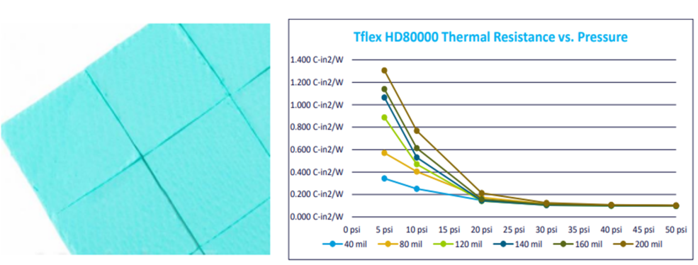
Thinner sheets of materials are commonly used between heat-dissipating electronics boxes and mounting surfaces to thermally sink the hot components to a colder surface and reduce the temperature of the electronics. The performance of these types of materials depends on reaching a certain contact pressure between components to ensure adequate heat transfer. Laird Performance Materials has developed many different types of thermal interface materials for a variety of applications. For example, their Tflex series, shown in Figure 7.5, is about 1 to 5 mm thick with a thermal conductivity of 6 W mK-1 (8), whereas their Tgon series of materials are about 0.13 to 0.5 mm thick with a thermal conductivity of 5 W mK-1 (9).
Thicker pad-like materials, such as Henkel brand GAP PADs®, are often used between high-heat-dissipating chips on electronic boards and the electronics enclosure. These are also made to fit a variety of applications, with varying materials, thickness, conformability, tear resistance, electrical isolation, thermal conductivity, and more (10). Several additional thermal interface materials developed by Henkel Corporation are shown in Figure 7.6. For conductive gaskets and interface materials, see Table 7-7.
| Table 7‑7: Thermal Interface Materials and Conductive Gaskets | ||
|---|---|---|
| Manufacturer | Product | Recommended Conductance (W/in2-C) |
| Parker Chomerics | Nusil CV-2946 | 3.5 |
| NeoGraf | Egraf HT-1210 | 2 |
| NeoGraf | Egraf HT-C3200 | 2.5 |
| Parker Chomerics | Chotherm 1671 | 0.75 |
| Parker Chomerics | Therm a gap 579 | 0.9 |
| Laird Performance Materials | T-PLI 220 | 1.5 |
| Henkel Corporation | Gap Pad 300 | 1.25 |
| Indium Corporation | Indium foil 0.005″ | 0.9 |
| Carbice Corporation | Structured Space Pad | 1.94 |
7.2.5 Sunshields
A sunshield, or sunshade, is an often-deployed device made up of a material with low solar absorptivity that reduces the amount of incident solar flux impinging on a spacecraft, by blocking the view to the Sun. Sunshields are commonly used for spacecraft thermal control, although they have only recently been designed for small spacecraft.
7.2.6 Thermal Louvers
Thermal louvers are thermally activated shutters that regulate how much heat the louvered surface can dissipate. As the louvers open, the average IR emissivity of the surface changes, changing how much heat the surface dissipates. Full-sized louvers on larger spacecraft have high efficacy for thermal control; however, integration on small spacecraft is challenging. Typical spacecraft louvers are associated with greater mass and input power, which are both limited on small spacecraft. Although commonly defined as active thermal control, in this context louvers are considered a passive thermal control component because the CubeSat-adapted design considered does not require spacecraft power.
7.2.7 Deployable Radiators
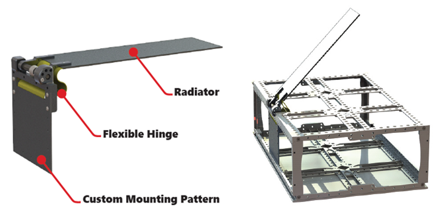
A radiator is a dedicated surface for dissipating excess heat via radiative heat transfer and has a high IR emissivity and low solar absorptivity—an optical property combination typically referred to as “radiator properties.” A deployable radiator is stowed during transit or when the radiator is not needed and deployed when excess heat dissipation is required. Deployable radiators on small spacecraft can be challenging due to volume constraints. While paint has been widely used to create efficient radiator surfaces on larger spacecraft, the relatively limited available external surface area on SmallSats that already have body-mounted solar cells reduces the available potential for creating dedicated radiative surfaces. For a system that requires a large amount of heat dissipation, a passive deployable radiator would greatly enhance thermal performance by increasing the available radiative surface area. Since deployable radiators may be needed because of a lack of radiator surfaces on the spacecraft body due to body-mounted solar cells, an alternate approach (more common for CubeSats) is to use the chassis body as the radiator area and have a deployable solar array. Also, deployed solar arrays would be able to radiate from a high emissivity/low solar absorptance backside for improved thermal management of the array. Figure 7.7 shows an example of a deployable thermal dissipation technology from Redwire Space.
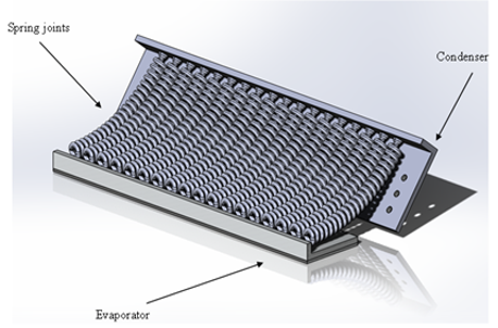
A novel deployable radiator is being developed by JPL, California Polytechnic San Luis Obispo, and California State University, Los Angles. At the core of this technology is an Additively Manufactured Deployable Radiator with embedded Oscillating Heat Pipes (AMDROHP) that enables heat to be efficiently transported across moving interfaces. The current AMDROHP radiator design is shown in Figure 7.8 and consists of an evaporator and a condenser plate, and a series of flexible joints connecting the two plates. AMDROHP can be stowed within a 3U CubeSat and can be passively deployed without the use of an actuator. This AMDROHP technology is currently in the testing phase and further design optimization is ongoing. This project is funded by NASA’s SSDS program in the University SmallSat Technology Partnerships initiative within the 2020 cohort.
7.2.8 Heat Pipes
A traditional heat pipe is a passive device comprised of a metal container (pipe) that holds a liquid under pressure and has a porous wick-like structure within the container. When heat is applied to one end of the tube, the liquid inside the tube near the hot end vaporizes and moves through the tube to the cooler end, where it condenses back into a liquid. The wick transports the condensed liquid back to the hot end via capillary action. There are also more complicated and non-passive types of heat pipes, such as variable conductance, diode, and loop heat pipes, which are not further explained in this document.
Heat pipes are an efficient passive thermal transfer technology, in which a closed-loop system transports excess heat via temperature gradients, typically from electrical devices to a colder surface, which is often either a radiator surface, or a heat sink that is thermally coupled to a radiator. Traditional constant conductance heat pipes are cylindrical in shape with a grooved inner wick, like those used on Bi-Spectral Infrared Detection (BIRD), a 92 kg satellite launched in 2001, to join satellite segments (13). Heat pipes can also be configured as flat plates with tubing sandwiched between two plates and charged with a working fluid. SDS-4, a 50 kg small spacecraft launched in 2012, incorporated the Flat-Plate Heat Pipe On-Orbit Experiment (FOX), developed at JAXA (14).
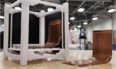
The FlexCool heat pipe by Redwire Space is a bent, flat heat pipe developed as a cross between a heat pipe and a thermal strap that can be customized for higher heat fluxes by increasing the thickness. This heat pipe flew on TechEdSat-10, a 6U CubeSat deployed from the ISS in 2020, to thermally manage the radio. An image of this technology in a 1U CubeSat model is shown in Figure 7.9.
7.2.9 Phase Change Materials and Thermal Storage Units
A phase change material used as a thermal storage unit is made up of a material (e.g., wax) within a metal housing with a heat source attached, so that as the source conducts heat to the enclosure, the phase change material within absorbs the energy as it changes phase (usually from solid to liquid). Then, as the heat source energy output reduces, the phase change material releases the energy as it changes back to its initial phase (usually from liquid to solid). Owing to the low thermal conductivity of the phase change material, the metal housing must conduct heat into the phase change material for efficient solidification or melting. See Table 7-8 for common phase change materials.
| Table 7‑8: Phase Change Materials | ||
|---|---|---|
| Material | Melting Point (°C) | Heat of Fusion (kJ/kg) |
| Salicylic Acid | 159 | 199 |
| Bee Wax | 61.8 | 177 |
| Paraffin | 20-60 | 140-280 |
| Polyethylene glycol 600 | 20-25 | 146 |
| Glycerol | 18 | 199 |
| Acetic acid | 17 | 187 |
| Water | 0 | 333 |
| Isopropyl alcohol | -89 | 88 |
| Butane | -135 | 76 |
| Ethane | -172 | 93 |
| Methane | -183 | 59 |
Thermal storage units are typically used with components that will experience repeated temperature cycling, or to slow down the temperature transient caused by a high heat dissipation event, or a temporary change in the environment such an eclipse. They can be challenging to apply to CubeSats and other small satellites because of the extra mass of the required housing.
Thermal Management Technologies developed a phase-changing thermal storage unit (TSU) that accounts for desired phase-change temperatures, interfaces, temperature stability, stored energy, and heat removal methodologies. This device will allow the user to control temperature peaks, maintain stable temperatures, and/or provide energy storage (15). Redwire Space developed multiple phase-change-materials (PCM)-based thermal energy storage panels for the CubeSat form factor that can be easily stacked between critical components (16.) Figure 7-10 shows two examples of thermal storage technology solutions: Q-Store and Q-Cache.
7.2.10 Thermal Switches
A thermal switch is a device that switches a heat conduction path between either a strong thermal coupling or a weak thermal coupling (thermal isolation) as needed to control the temperature of heat-producing components. A switch typically connects a heat-producing component and a low-temperature sink, such as a radiator. Heat switches differ from thermostats in that they passively modulate thermal coupling, while thermostats modulate heater circuits (17). Part of the challenge with the integration of a thermal switch in SmallSats is that they take up additional space between a component and a heat sink. Typical, heat switches may provide a conduction ratio of 10:1, with a technology goal of 100:1 (18). See Table 7-9 for examples of commercial thermal switches.
| Table 7‑9: Thermal Switches | |||||||
|---|---|---|---|---|---|---|---|
| Manufacturer | Product | Type | Max Conductance | Min Conductance | Mass | Max Q | Notes: |
| ACT | (Study) | VCHP | 20 W/K | 0.01 to 0.04 W/K | 0.3 to 0.5 kg | — | VCHP Variable Cond. Heat Pipe) |
| Sierra Space | Passive Thermal Control Heat Switch | Mechanical | 1 W/K | 0.015 W/K | ~0.110 kg | 6 W | Originally designed for Martian surface ops. |
| Sierra Space | HP Thin Plate | Mechanical | 607 W/m^2/°C | 7.8 W/m^2/°C | 2.72 g/cm^3 | 12 W | Based on single “cell” design (25.4 mm x 25.4 mm) |
| Sierra Space | Diaphragm Thin Plate | Mechanical | 607 W/m^2/°C | 7.1 W/m^2/°C | 2.72 g/cm^3 | 12 W | Based on single “cell” design (41.3 mm x 41.3 mm) |
7.2.11 Multifunctional Thermal Structures
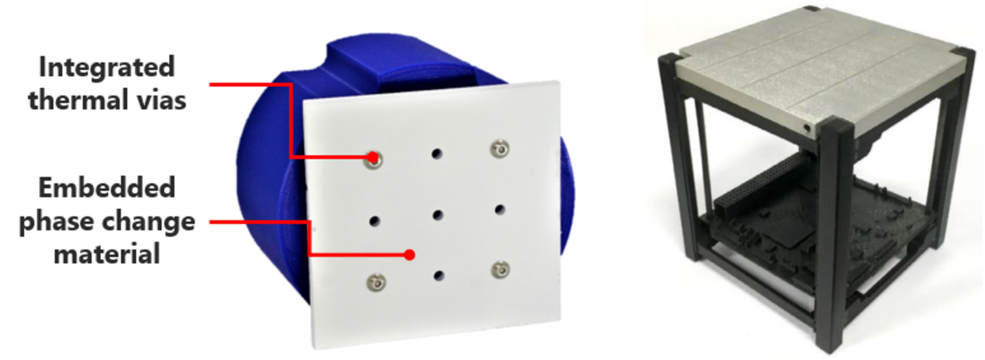
A newer development in passive thermal control for small spacecraft is multifunctional thermal structures. These integrate thermal control capabilities directly into the structure. This is particularly advantageous for small spacecraft due to their strict mass and volume constraints. Currently, Thermal Management Technologies has adapted its multifunction heat spreading structure technology, scaled it to smaller satellite configurations, and designated it Standard Passive Orbital Thermal-control (SPOT) Structures. SPOT Structures come in four standard configurations: 6U, 12U, Launch-U, and ESPA (19). Each incorporates heat-spreading technology that improves the ability to radiate waste heat. They incorporate features such as low mass, high stiffness and strength, and integrated heat pipes. This new technology is at TRL 4.
7.3 State-of-the-Art – Active Systems
Active thermal control methods rely on input power for operation and have been shown to be more effective in maintaining tighter temperature control for components with more stringent temperature requirements or higher heat loads (20). Typical active thermal devices used on large-scale spacecraft include electrical resistance heaters, cryocoolers, thermoelectric coolers, and fluid loops. Electrical heaters are usually easily integrated into SmallSat architectures as they do not typically require significant mass or volume. Heaters are frequently used in all space applications, including small and large satellites; therefore they are often included as passive thermal control technology. Other active systems are challenging to integrate into CubeSats and other small satellites because of the power, mass, and volume requirements associated with each technology. Until spacecraft designers can miniaturize existing actively controlled thermal techniques and reduce power requirements or increase available spacecraft power, most active thermal systems in small spacecraft are limited and have a TRL range of 3-6. Descriptions of SmallSat active thermal technologies are provided in Table 7-10.
| Table 7‑10: SmallSat Active Thermal Technologies | |
|---|---|
| Active Technology | Description |
| Electrical Heaters | Space heaters use an electrical-resistance element in between two sheets of flexible electrically insulating material. |
| Cryocoolers | Miniature refrigeration system designed to cool components to extremely low temperatures. |
| Thermoelectric Coolers (TEC) | Miniature solid-state heat pumps which provide localized cooling via the Peltier effect, which is cooling resulting from passing electric current through a junction formed by two dissimilar metals |
| Fluid Loops | System that circulates a working fluid through the spacecraft to a heat sink. |
7.3.1 Heaters
Electrical resistance heaters used on small spacecraft are most often Kapton heaters, which consist of a polyimide film with etched foil circuits that produce heat when electrical current is applied. Kapton heaters also often have a pressure-sensitive adhesive on one side for easy application. Heaters are usually controlled by a thermostat or temperature sensor and used in cold environments to maintain battery temperatures, typically for components with the narrowest temperature limits. The low mass of SmallSats requires little additional heater power to maintain temperature limits, and therefore heaters do not typically need to be very high power to effectively manage temperatures. The TRL values for electrical heaters on SmallSats are 7-9 in LEO environments.
The 1U CubeSats Compass-1, MASAT-1, and OUTFI-1 each required an electrical heater attached to the battery in addition to passive control for the entire spacecraft system to maintain thermal regulation during eclipse periods (21). Additionally, as biological payloads become more common on small spacecraft, their temperature limits must also be considered and maintained. NASA ARC biological nanosats (GeneSat, PharmaSat, O/OREOS, SporeSat, EcAMSat, and BioSentinel) all used actively controlled heaters for precise temperature maintenance of their biological payloads, with closed-loop temperature feedback. See Table 7-11 for examples of electrical heaters for active thermal systems.
| Table 7-11: Active Thermal Systems – Electrical Heaters | |||||
|---|---|---|---|---|---|
| Manufacturer | Product | Power (W/cm2) | Temp Limits | Material | Notes: |
| Omega | KHLVA, PLM-Series | 0.4 to 1.56 | -40°C to 149°C (w/PSA) -57°C to 232°C (w/o PSA) | Kapton (polyimide) | Various sizes, rectangular/square/round, w & w/o pressure sensitive adhesive (PSA), Low-Outgassing |
| Omega | Polyimide Heater Kit | 0.4 to 1.56 | -200°C to 200°C (w/PSA) | Kapton (polyimide) | Various shapes. 149°C for continuous ops due to PSA limits. |
| Tempco | SHK Series | 0.8 to 6.2 | -35°C to 150°C (w/ Al Foil) | Kapton (polyimide) Some w/ Al Foil | Rectangular/square/round, w/ (PSA). Some model available w/ AL foil for extended temp limits. |
| Tayco | Flexible Circuit Heater | Up to 3.1 | -200°C to 200°C | Kapton (polyimide) | Various shapes and watt densities. |
| Hi-Heat Industries | Polyimide Flexible | Up to 3.1 | -200°C to 200°C | Kapton (polyimide) | Quick turnaround for custom sizes and resistances |
| Minco | Polyimide Thermofoil HK Series | 0.8 to 5.1 | -200°C to 200°C -200°C to 150°C (w/ Al Foil) | Kapton (polyimide) Some w/ Al Foil | Mountings: #12 & arcrylic PSA, epoxy, shrink band, stretch tape, clamping. NASA rated for materials & vacuum. |
| Birk Manufacturing | Polyimide-Traditional | 0.02 to 3.1 | See Notes | Kapton (polyimide) | Max Temps: FEP-Bonded & All Polyimide(260°C); Acrylic Bonded(120°C). |
| Birk Manufacturing | Polyimide-High Temp | 0.02 to 7.75 | See Notes | Kapton (polyimide) | Max Temp: up to 300°C |
| Chromalox | KPH, KPM Series | 0.4 to 1.56 | -200°C to 200°C* -200°C to 121°C** | Kapton (polyimide) | * FEP Construction, Acrylic construction |
| All Flex Solutions | Custom Designs | See website for design guide, options. | |||
7.3.2 Cryocoolers
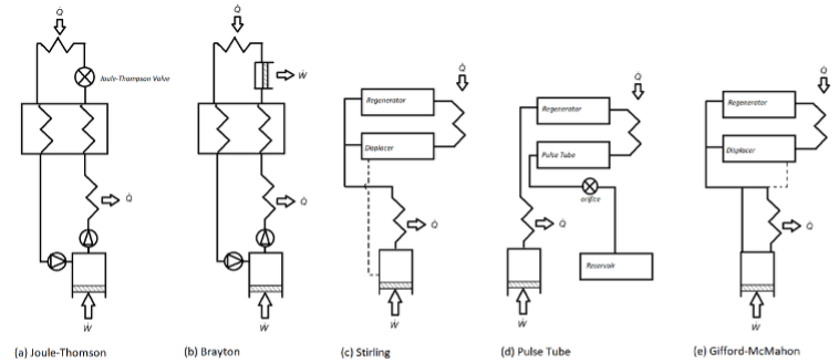
Cryocoolers are refrigeration devices designed to cool to temperatures of approximately 100K and below. A summary of cryocooler systems is given in Figure 7.11, and a detailed review of the basic types of cryocoolers and their applications is provided by Radebaugh (22). The first two systems (a) and (b) are recuperative cycles, while (c), (d), and (e) are regenerative cycles. Cryocoolers are used on instruments or subsystems requiring cryogenic cooling, such as high-precision IR sensors. Instruments such as imaging spectrometers, interferometers, and midwave infrared (MWIR) sensors require cryocoolers to function at extremely low temperatures. The low temperature improves instrument dynamic range and extends the wavelength coverage. The use of cryocoolers is also associated with longer instrument lifetimes, low vibration, high thermodynamic efficiency, low mass, and cooling temperatures less than 50K (23). Cryocoolers on small spacecraft are still a new concept; however, there have been two CubeSats with cryocooling on board. Lunar IceCube, a 6U secondary payload launched on Artemis I in 2022 and developed by Morehead State University, used a 600 mW cryocooler for its BIRCHES point spectrometer (24). For more examples of cryocooler solutions, see Table 7-12.
| Table 7-12: Active Thermal Systems – Cryocoolers | |||||||
|---|---|---|---|---|---|---|---|
| Manufacturer | Product | Form factor | Life (yrs) | Mass (kg) | Power (W) | TRL | Notes: |
| Lockheed Martin Space | MICRO1-1 | ~1U | 10 | 0.350 | 15 | 7 – 9 | 1 W cooling @150K cold tip. Integrated on LunIR CubeSat (launcher: Artemis I). |
| MICRO1-2 | ~1U | 10 | 0.475 | 25 | 6 | 2 W cooling @105K cold tip. Tested for MISE. Tentatively slated for integration into Europa Clipper. | |
| MICRO1-3 | ~1U | 10 | 40 | 5 | Original design point: 1.4 W cooling @105K (40 W). Max Cooling: 2.9 W @200K (30 W). | ||
| AIM Infrarot-Module GmbH | SF070 | ~1U | >3.5 (MTTF) | 0.85 | 24 | 6 – 9 | 0.6 W @80K cold tip. Slated from HyTi: Hyperspectral Thermal Imager (6U CubeSat). |
| SunPower – Ametek | CryoTel DS Mini | <2U | >14 | 1.20 | 45 | 6 | 1.8 W @77K (23°C reject). Op to 40K. |
| CryoTel MT | <3U | >23 | 2.10 | 80 | 6 | 5 W @77K (23°C reject). Op to 40K. | |
| Ricor | K508N | 1U+ | 15 | 0.475 | 5.5 | 4 – 6 | 0.2 W @80K (23°C reject). Demo for ‘Active CryoCubeSat (ACCS)’ project. |
| TRL values provided are specific to low-Earth environments for SmallSats <180 kg. | |||||||
7.3.3 Thermoelectric Coolers (TEC)
TECs are miniature solid-state heat pumps that provide localized cooling via the Peltier effect, which is cooling resulting from passing an electric current through a junction formed by two dissimilar metals. TECs have been used to cool star trackers, IR sensors, and low-noise amplifiers on large spacecraft. Advantages of TECs are that they have no moving parts and are reliable, noiseless, lightweight, and compact. Their use is limited below temperatures of 130 K due to low efficiency and reduced performance at large temperature differences. Furthermore, TECs are mechanically fragile and highly sensitive to thermal expansion stresses. External stresses can be mitigated by adding a thermally conductive strap on the cold side (25). Table 7-13 provides an overview of commercial thermoelectric coolers.
| Table 7-13: Thermoelectric Coolers | |||||
|---|---|---|---|---|---|
| Manufacturer | Product | Cooling Capacity | ΔT @ 27°C | Operating Temp | Notes: |
| Laird Technologies | Examples: CP Series PolarTec PT Series UltraTEC UTX Series HighTemp ETX Series Multistage MS Series | 1.8 – 118 W 18 – 71 W 69 – 299 W 7.7 – 322 W 0.3 – 38 W | 68 – 74°C 68 – 74°C 68 – 74°C 68 – 74°C 81 – 129°C | < 80°C < 80°C < 80°C < 150°C < 80°C | |
| Custom Thermoelectric | 04801-9A30-18RB | 6.1 W | 70°C (Max) | < 200°C | |
| FerroTec | 9502/031/018 M | 4.1 W | 70°C (Max) | Values @ 50°C | |
| Coherent (formerly Marlow) | Muti Stage SP2394-07AB | 4.5 W | 130°C (Max) | < 85°C | Values @27°C, Designed for zero/high G |
| Coherent (formerly Marlow) | Single Stage CT12-4 | 37.0 W | 70°C (Max) | < 130°C | Values @27°C, Designed for zero/high G |
7.3.4 Fluid Loops
A pumped fluid loop (PFL) consists of a circulating pump that moves a liquid through tubing connected to a heat exchanger and a heat sink. A heat source is mounted to the heat exchanger, and the pumped fluid carries the heat from the source to a heat sink, typically a radiator; the cooled fluid is returned to the heat source to continue providing cooling. A PFL is capable of cooling multiple locations via forced convective fluid cooling. Mechanically pumped fluid loops (MPFL) are not typically used on SmallSats because they are associated with higher power consumption and mass.
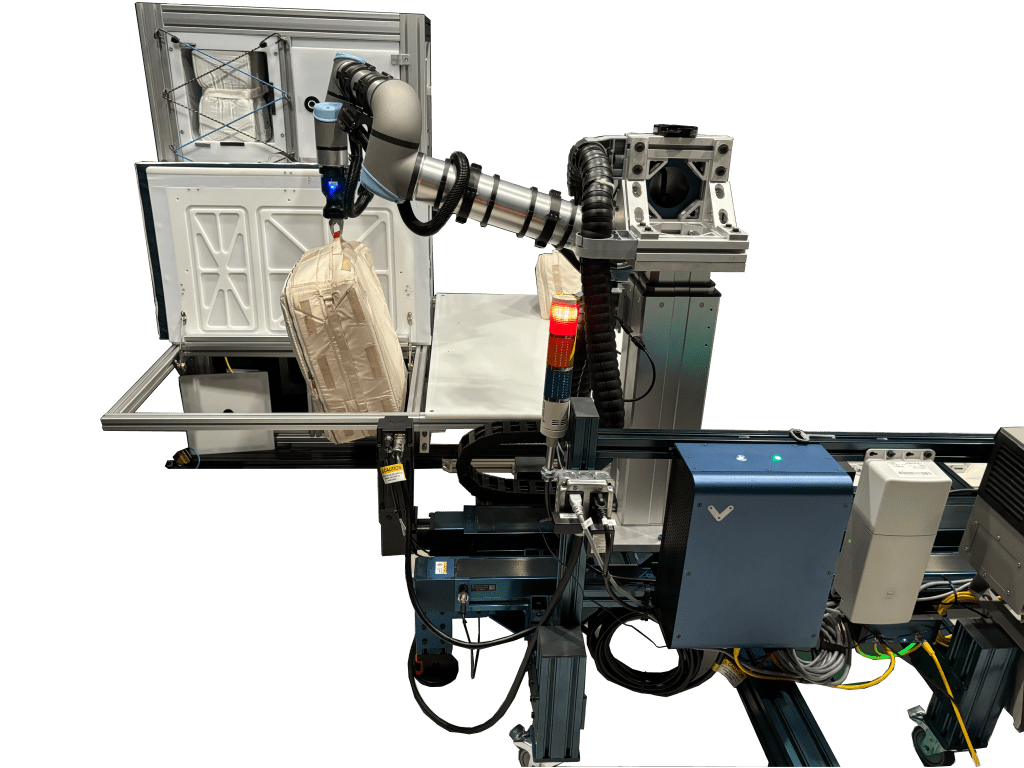
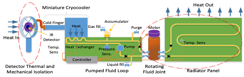
The Active Thermal Architecture (ATA) system is an advanced, active thermal control technology for small satellites in support of advanced missions in deep space, heliophysics, Earth science, and communications. The ATA technology is capable of high-power thermal rejection and zonal temperature control of satellite buses, payloads, and high-energy-density components. The ATA system includes integrated heaters and a PID-based control algorithm to dynamically tune the satellite’s thermal rejection and zonal temperature control as a function of payload and mission parameters. The ATA project was developed by the Center for Space Engineering at Utah State University and funded by the NASA SSDS in partnership with JPL. The ATA is a sub-1U two-stage active thermal control system targeted at 6U CubeSat form factors and larger. The first stage consists of an MPFL with a micro-pump that circulates a single-phase heat transfer fluid between an internal heat exchanger and a deployed tracking radiator. The second stage is composed of a miniature tactical cryocooler that directly provides cryogenic cooling to payload instrumentation. The conceptual operation of the ATA system is shown in Figure 7.13. The ATA system is scheduled to fly on the upcoming ACMES mission, a technology demonstration flight funded by NASA ESTO through an InVEST grant.
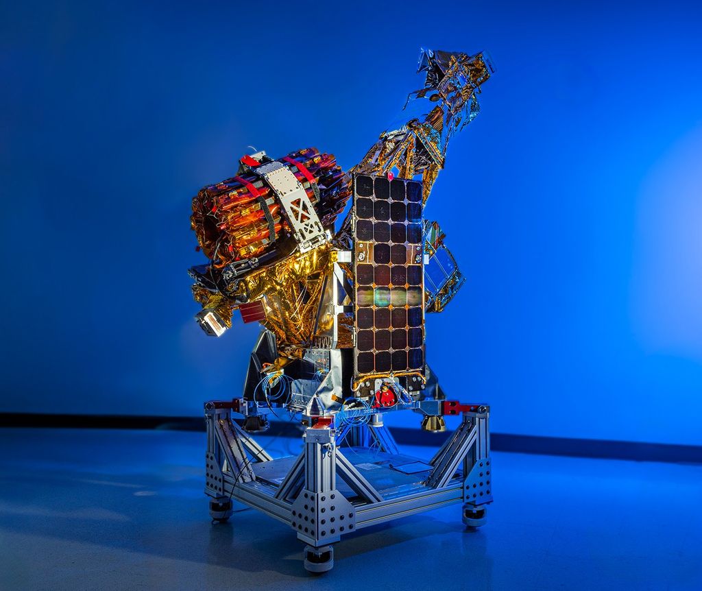
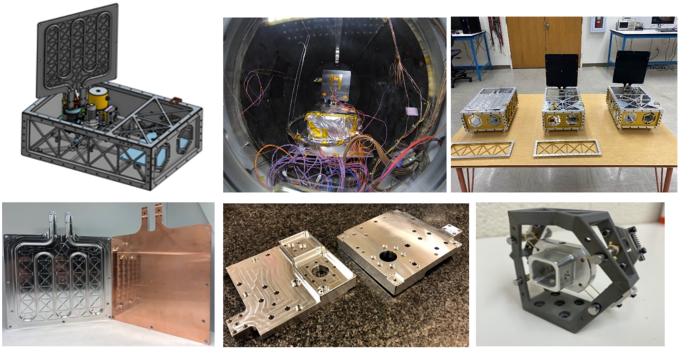
Ultrasonic additive manufacturing (Fabrisonics UAM) techniques were used to simplify and miniaturize the ATA system by embedding the MPFL fluid channels directly into the integrated HX, CubeSat chassis, and the external radiator, to create integrated multifunctional structures. By leveraging UAM 3D printing, the ATA system can improve baseline thermal performance by >200%, a mass savings of more than >30%, and a savings on cost and schedule of better than >50%. The ATA system also features flexible, multi-axis rotary fluid unions and an integrated geared micro-motor, which enables the two-stage deployment and solar tracking of the ATA radiator. The ATA features passive vibration isolation and jitter cancellation technologies such as a floating wire-rope isolator design, particle damping, flexible PGS thermal links, and a custom Kevlar isolated cryogenic electro-optical detector mount. Figure 7.14 shows some of the technologies developed for ATA, as well as the ground-based prototype CubeSat.
| Table 7-14: Active Thermal Systems – Fluid Loops | ||||||
|---|---|---|---|---|---|---|
| Manufacturer | Product | Cooling Capacity | Mass | Volume | TRL | Notes: |
| Netherlands Aerospace Centre | Mini-MPL | >20 W | – | < 1U | 4 – 6 | Scalable to ≤ 200W |
| Lockheed Martin | Joule-Thomson Microcryocooler | – | 0.2 kg | < 1U (Est.) | 4 – 5 | |
| TRL values provided are specific to low-Earth environments for SmallSats <180 kg. | ||||||
7.4 Summary
As thermal management on small spacecraft is limited by mass, surface area, volume, and power constraints, traditional passive technologies such as paints, coatings, tapes, MLI, and thermal straps continue to dominate thermal design. Active technologies, such as thin, flexible resistance heaters, have also seen significant use in small spacecraft, including some with advanced closed-loop control. Many technologies that have to date only been integrated on larger spacecraft are being designed, evaluated, and tested for small spacecraft to meet the growing needs of SmallSat developers as these systems become more advanced. Deployable solar panels that have been used by many SmallSats are paving the way for deployable thermal components, while advanced deployable radiators and thermal storage units are still undergoing testing for small spacecraft.
More active thermal control system technologies are being developed to accommodate volume and power restrictions of smaller spacecraft; cryocoolers are being designed to fit within 0.5U volumes, which will allow small spacecraft to use optical sensors and imaging spectrometers.
For feedback solicitation, please email: arc-sst-soa@mail.nasa.gov. Please include a valid business email.
References
- A. Anvari, F. Farhani, and K. S. Niaki. “Comparative Study on Space Qualified Paints Used for Thermal Control of a Small Satellite.” 2009.
- Sheldahl, A Flex Company. “The Red Book.” Jan 24, 2020 REV E. Available at: https://www.sheldahl.com/sites/default/files/2020-02/RedBook_0.pdf
- Thermal Management Technologies. “Products, Thermal Components: Flexible Thermal Straps.” Accessed 2018. [Online] Available at: https://www.tmt-ipe.com/thermal-components
- Boyd Corporation. “Flexible Thermal Conductors — Thermal Straps & Strap Assemblies.” Datasheet. 2020. [Online] Accessed 2022. Available at: https://info.boydcorp.com/hubfs/Thermal/Conduction-Cooling/Boyd-Thermal-Straps-Technical-Datasheet.pdf
- Technology Applications, Inc. “Graphite Fiber Thermal Straps (GFTS).” 2022. [Online] Available at: https://www.techapps.com/graphite-fiber-thermal-straps
- Thermotive. “Products: Thermal Straps.” 2019. [Online] Available at: http://www.thermotive.com/thermalstraps.html
- D., Gilmore. “Spacecraft Thermal Control Handbook, Volume I, Fundamental Technologies, Chapter 8: Mountings and Interfaces.” 2002.
- Laird Technologies. Tflex HD80000 Series Thermal Gap Filler. Laird Technologies. Datasheet. [Online] Available at: https://www.laird.com/sites/default/files/tflex-hd80000-datasheet.pdf
- Laird Technolgies. “Tgon 800 Series Electrically and Thermally Conductive Interface Pad.” Datasheet. [Online] Available at: https://www.laird.com/sites/default/files/tgon-800-datasheet.pdf
- Henkel Corporation, Bergquist. “Thermal Interface Materials Selection Guide. Bergquist.” 2019. [Online] Available at: https://dm.henkel-dam.com/is/content/henkel/lt-8116-brochure-thermal-interface-materials-selection-guidepdf
- Thermal Management Technologies. “Thermally Efficient Deployable Radiators.” Datasheet. 2021. [Online] Available at: https://www.tmt-ipe.com/product-sheets
- E. Urquiza, B.X. Zhang, M.P. Thelen, J.I. Rodriguez, and S. Pellegrino. “Folding Elastic Thermal Surface – FETS.” June 1, 2013. [Online] Available at: https://www.techbriefs.com/component/content/article/tb/pub/techbriefs/mechanics-and-machinery/16598
- H.J. Kramer. “BIRD (Bi-Spectral Infrared Detection).” May 25, 2012. [Online] Available at: https://directory.eoportal.org/web/eoportal/satellite-missions/b/bird
- Y. Nakamura et al. “Small Demonstration Satellite-4 (SDS-4): Development, Flight Results, and Lessons Learned in JAXA’s Microsatellite Project.” 27th Annual AIAA/USU Conference on Small Satellites, Logan, UT. 2013.
- Thermal Management Technologies. “Thermal Storage Units.” Datasheet. 2021. [Online] Available at: https://www.tmt-ipe.com/product-sheets
- Redwire Space. “Thermal Energy Storage Panel: Q Store.” 2022. [Online] Available at: https://redwirespace.com/products/qstore/?rdws=nnn.szex.tfd&rdwj=43870
- D. Gilmore. Spacecraft Thermal Control Handbook, Volume I, Fundamental Technologies, Chapter 10: Heat Switches. 2002.
- NASA. NASA Technology Taxonomy and the NASA Strategic Technology Integration Framework, TX 14: Thermal Management Systems. July 2020. [Online] Available at: https://www.nasa.gov/sites/default/files/atoms/files/2020_nasa_technology_taxonomy_lowres.pdf
- Thermal Management Technologies. “Products: Small Spacecraft Structures. Thermal Management Technologies.” 2019. [Online] Available at: https://www.tmt-ipe.com/small-spacecraft-structures
- K. Hogstrom. “State-of-the-Art Thermal Analysis Methods and Validations for Small Spacecraft,” Ae241 Literature Survey. March 4, 2013.
- D. Hengeveld, J. Braun, E. Groll, and A. Williams. “Review of Modern Spacecraft Thermal Control Technologies and Their Application to Next-Generation Buildings.” 2010. International High Performance Buildings Conference. Paper 40.
- R. Radebaugh. “Refrigeration for superconductors.” 2004, IEEE, pp. 1719 – 1734.
- R. Hon, C. Kesler, and D. Sigurdson. “Integrated Testing of a Complete Low-Cost Space Cryocooler System.” 2009.
- B. K. Malphrus et al. “The Lunar IceCube EM-1 Mission: Prospecting the Moon for Water Ice.” Institute of Electrical and Electronics Engineers A&E Systems Magazine. April 2019.
- D., Gilmore. “Spacecraft Thermal Control Handbook, Volume I, Fundamental Technologies, Chapter 13: Thermoelectric Coolers.” 2002.
- P. Champagne, J.R. Olsen, T. Nast, E. Roth, A. Collaco, G. Kaldas, E. Saito, V. Loung. “Development of a J-T Micro Compressor.” IOP Conf. Series: Materials Science and Engineering 101 (2015) 012009.