


Orion Components

Launch Abort System
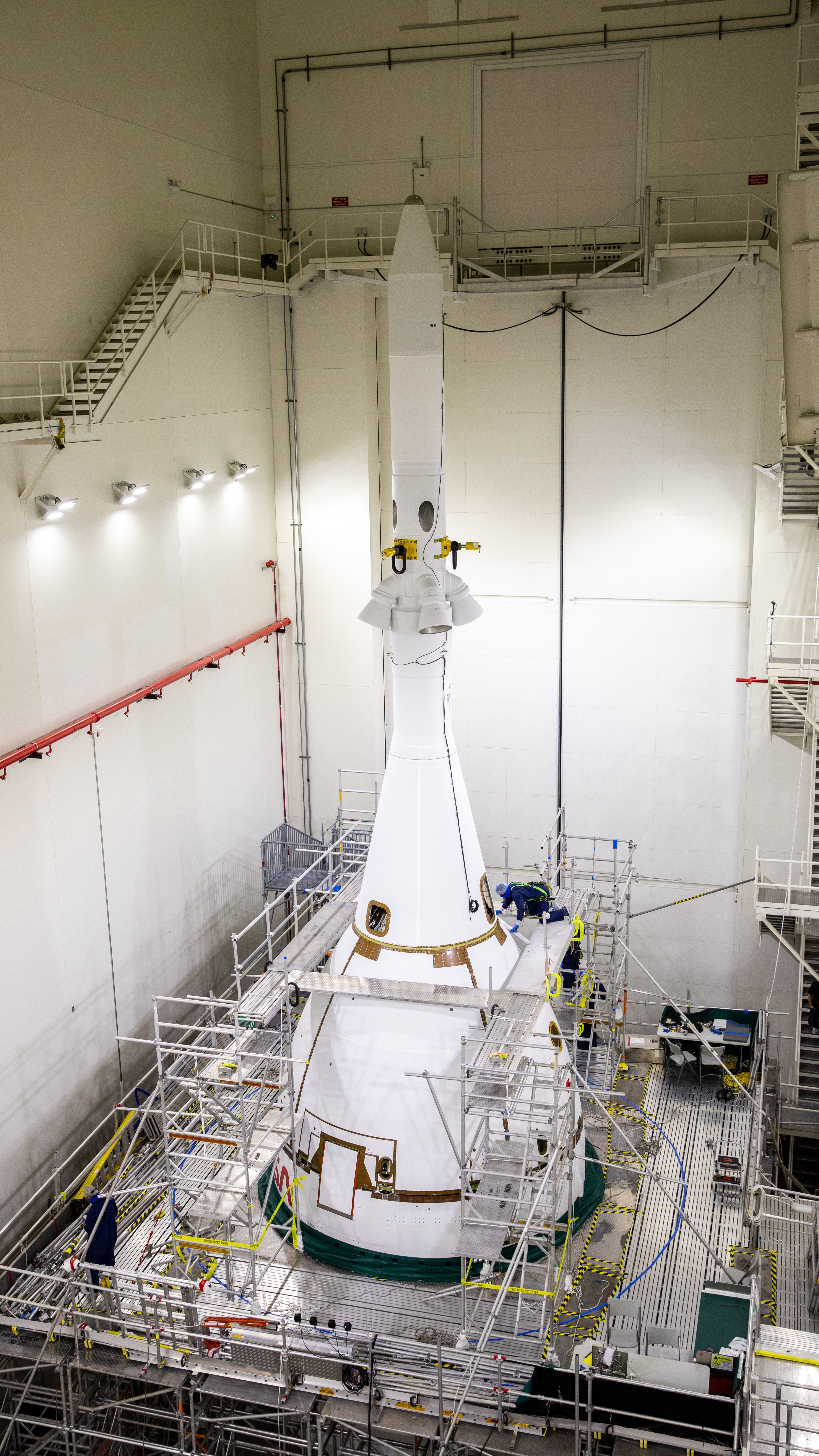
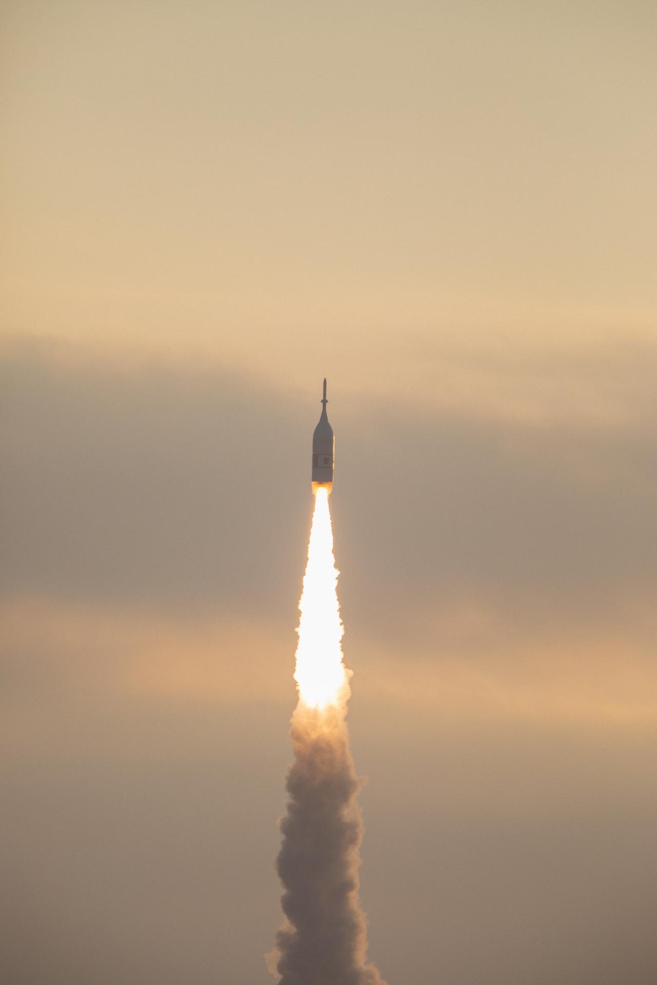
Orion’s launch abort system (LAS) is designed to carry the crew to safety in the event of an emergency during launch or ascent atop the agency’s Space Launch System (SLS) rocket. It can activate within milliseconds to pull the vehicle to safety and position the crew module for a safe landing.
The LAS is divided into two parts: the fairing assembly and the launch abort tower. The fairing assembly is a shell composed of a lightweight composite material that protects the capsule from the heat, wind, and acoustics of the launch, ascent, and abort environments. The launch abort tower includes the system’s three motors.
In the case of an emergency, the three solid rocket motors work together to propel the astronauts inside Orion’s crew module to safety: the abort motor pulls the crew module away from the launch vehicle; the attitude control motor steers and orients the capsule; then the jettison motor ignites to separate the LAS from the crew module prior to parachute deployment.
During a normal launch, once the SLS clears most of the atmosphere, the job of the LAS is done. The jettison motor fires to separate the LAS from the spacecraft, and from this point, abort scenarios are handled by the engines in the service module. Fully jettisoning the entire LAS once it’s no longer needed frees Orion of thousands of pounds that will make it lighter for its trips into space.
The tower-like abort structure is specifically built for deep space missions and to ride on a high-powered rocket. It is positioned with its motors on top of the Orion crew module and designed to pull the crew module away from the rocket, rather than push it away with motors at the base, as some other escape systems are built to do. This design minimizes the mass that aborts in an emergency by leaving the service module behind.
The abort motor generates 400,000 pounds of thrust, making Orion’s LAS the highest acceleration escape system ever tested. The puller-style system with the tower above the spacecraft is the first of its kind capable of controlled orientation after separating from the rocket. In the event of an abort, the LAS can outrun even the SLS rocket, which generates 8.8 million pounds of thrust.
The LAS development is managed by NASA’s Langley Research Center and Marshall Space Flight Center.
Launch Abort System Quick Facts
| Height | 50 ft. with ogive panels 44 ft. without ogive panels |
| Diameter | 3 ft. tower 17 ft. at base |
| Liftoff Weight | 17,000 lbs. |
| Propellant Weight | 5,700 lbs. |
| Abort Motor Weight | 7,600 lbs. includes 4,700 lbs. propellant 400,000 lbs. thrust |
| Altitude Motor Weight | 1,700 lbs. includes 650 lbs. propellant 7,000 lbs. thrust |
| Jettison Motor Weight | 900 lbs. includes 350 lbs. propellant 40,000 lbs. thrust |
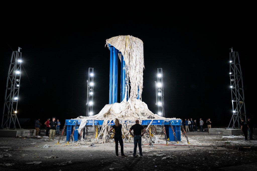
The abort motor on Orion’s launch abort system (LAS) generates 400,000 pounds of thrust in a matter of milliseconds to quickly propel the crew module away from danger
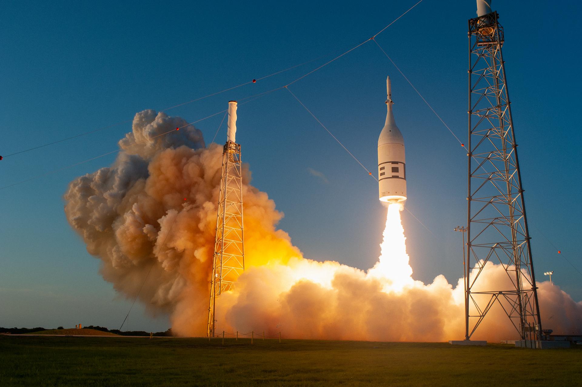
From a launch pad abort, Orion’s LAS accelerates from 0 to 500 mph in 2 seconds.
The LAS solid rocket motors use propellant that burns at a temperature of 4,456°F, nearly half the temperature on the surface of the Sun.
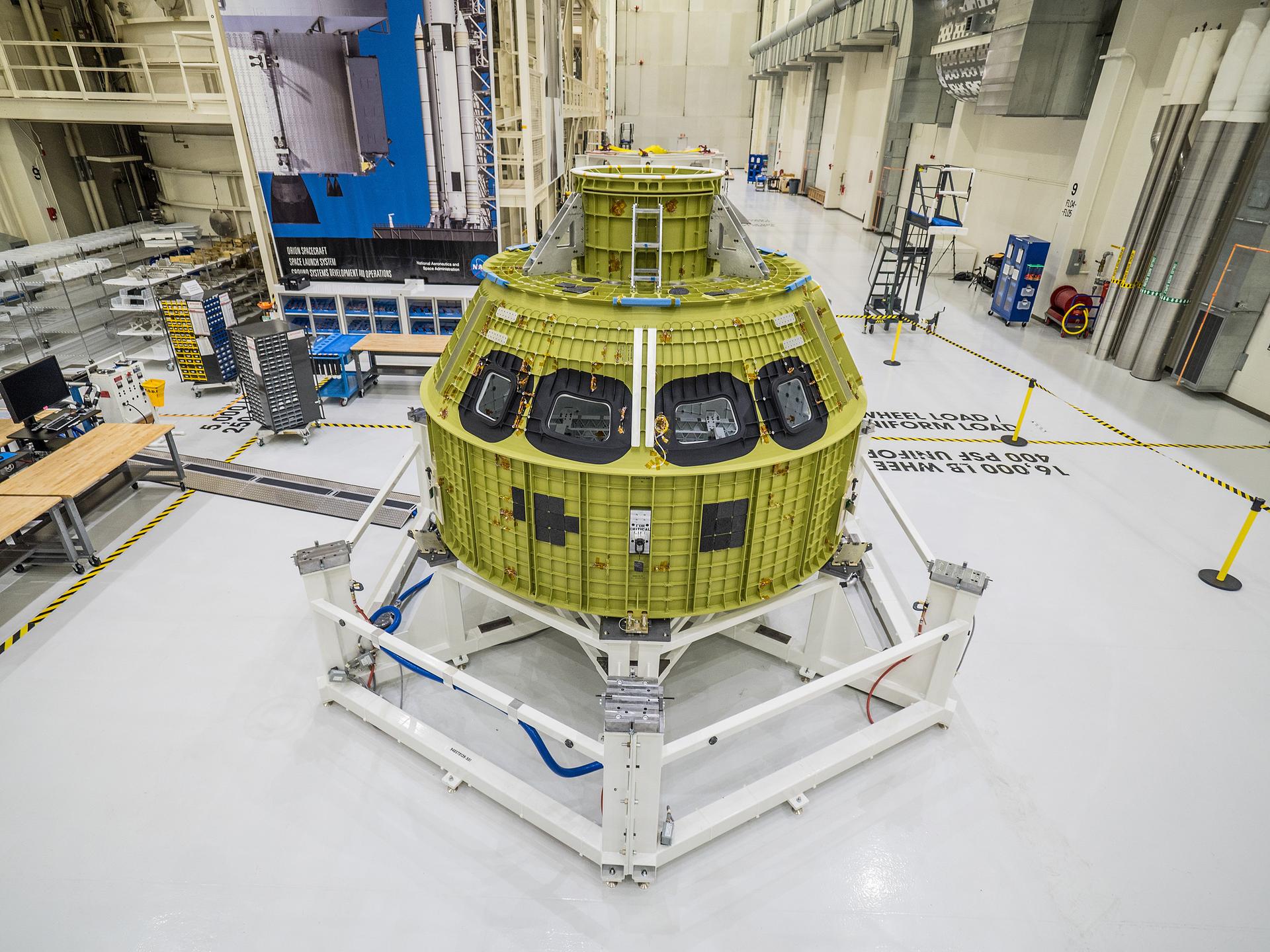
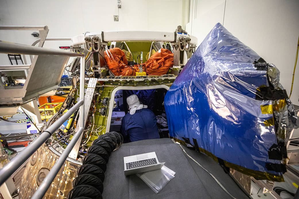
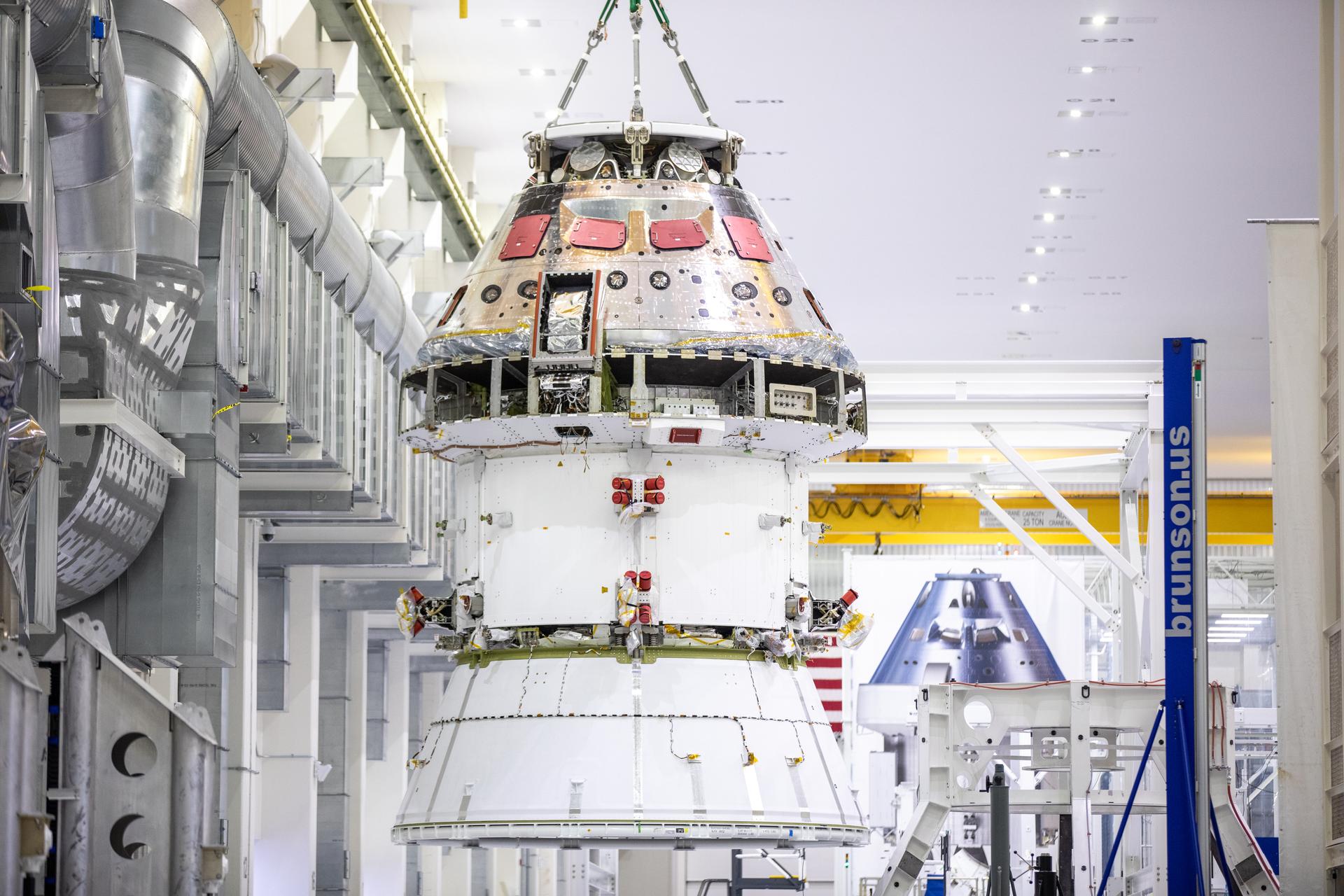
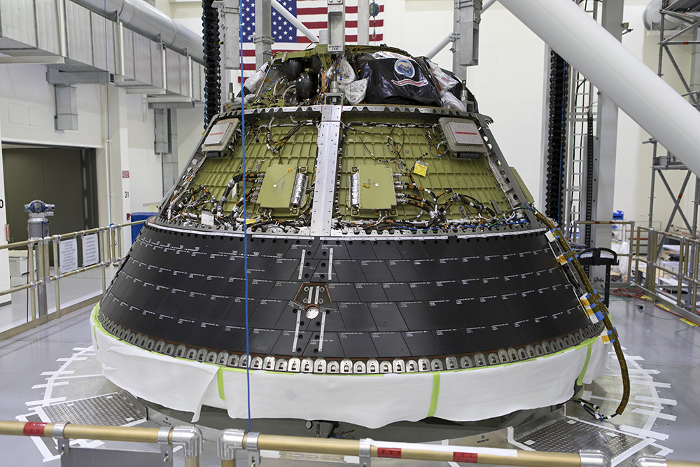
Crew Module
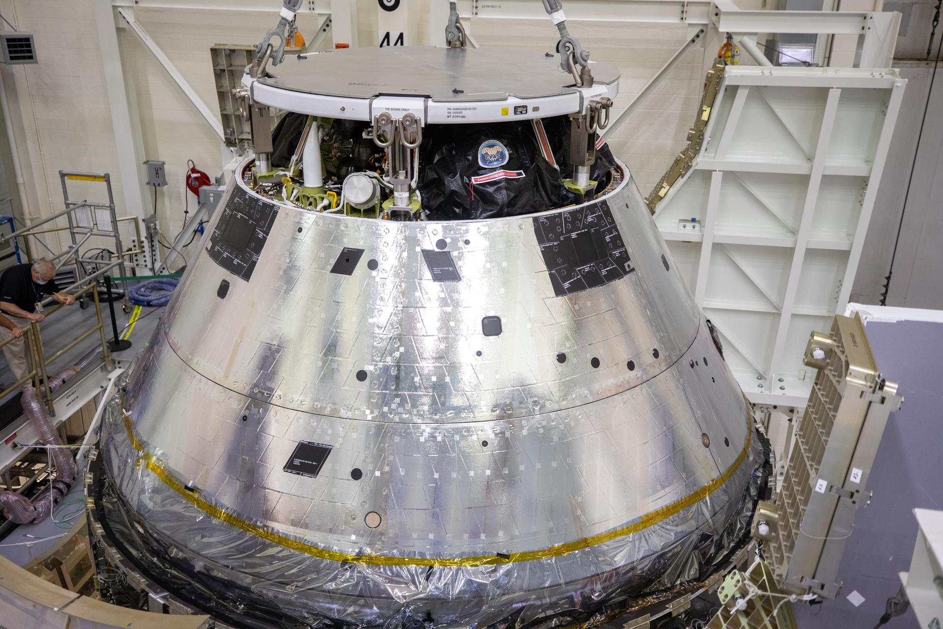
The crew module is the pressurized part of the Orion spacecraft, sometimes referred to as the capsule, where crew will live and work on their journey to the Moon and back. The crew module can accommodate four crew members for up to 21 days, and provides a safe habitat through launch, on-orbit operations, landing, and recovery. The crew module contains advances in life support, avionics, power systems, and advanced manufacturing techniques, and is the only portion of Orion that returns to Earth at the end of flights.
Inside the crew module, environmental control and life support systems maintain cabin temperature, pressure, humidity, oxygen, and carbon dioxide levels, keeping crew healthy and comfortable on long missions. A cockpit with glass displays allows full control of Orion by the crew. The sealed capsule also provides radiation protection needed to safeguard crew and spacecraft systems from cosmic and solar radiation seen in deep space, and micrometeoroid protection from items found in the space environment.
On missions to the Moon, the crew module will be home to the astronauts. Water tanks and a dispenser provide drinking water and a simple way to rehydrate and warm food. The crew module’s waste management system, or lavatory, is designed for multi-week missions, privately accommodating both sexes while in zero gravity. Astronauts will also have to exercise, and Orion’s crew module has a built-in exercise device that provides both aerobic and strength training. The environmental control system even removes excess heat, humidity, and odor during exercise.
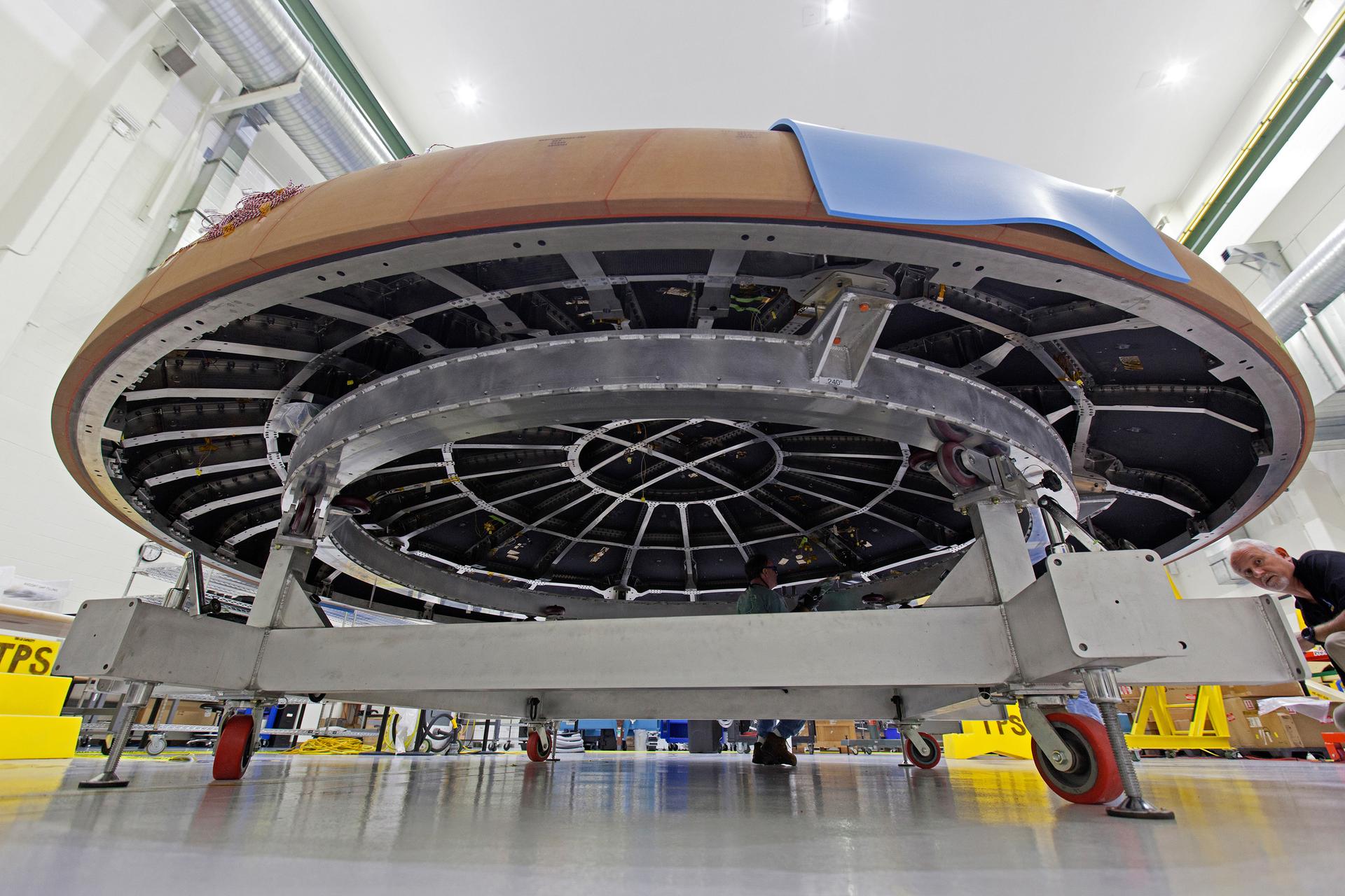
The underlying structure of the crew module is called the pressure vessel. The pressure vessel consists of seven large aluminum alloy pieces that are joined together using friction-stir welding to produce a strong, yet light-weight, air-tight capsule. The seven major structural pieces include the barrel, tunnel, forward and aft bulkheads, and three cone panels. Original designs had 33 welded pieces, but the Artemis I crew module and beyond have seven welded pieces, improving manufacturability and saving more than 700 pounds of excess weight.
The floor structure where the crew seats are attached and where the crew stowage lockers are located is called the backbone assembly, which is a nine-piece bolted structure of crisscrossing beams. The backbone, made of aluminum, also provides additional structural support for the crew module. Most of the equipment the crew needs to live in space, such as food, medical kits, emergency equipment such as masks and fire extinguisher, sleeping bags, and the pressure suits worn for launch and return to Earth are stored in lockers located here.
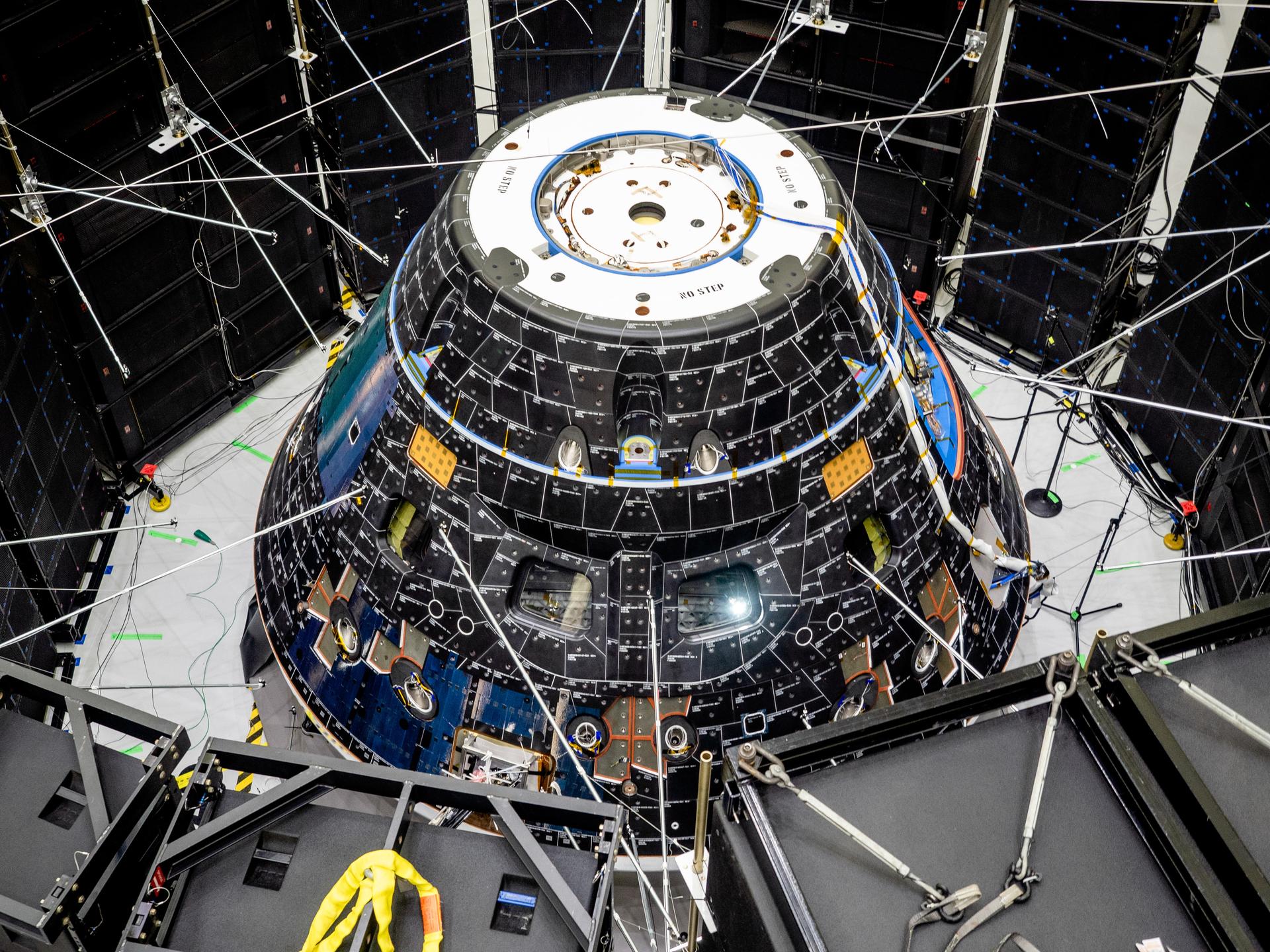
Covering the pressure vessel is the protective cover on the sides of the crew module known as the backshell, made up of 1,300 thermal protection system tiles. The tiles are made of a silica fiber material similar to those used for more than 30 years on the space shuttle. The tiles will protect the spacecraft from both the coldness of space and the extreme heat of entry into Earth’s atmosphere.
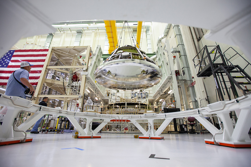
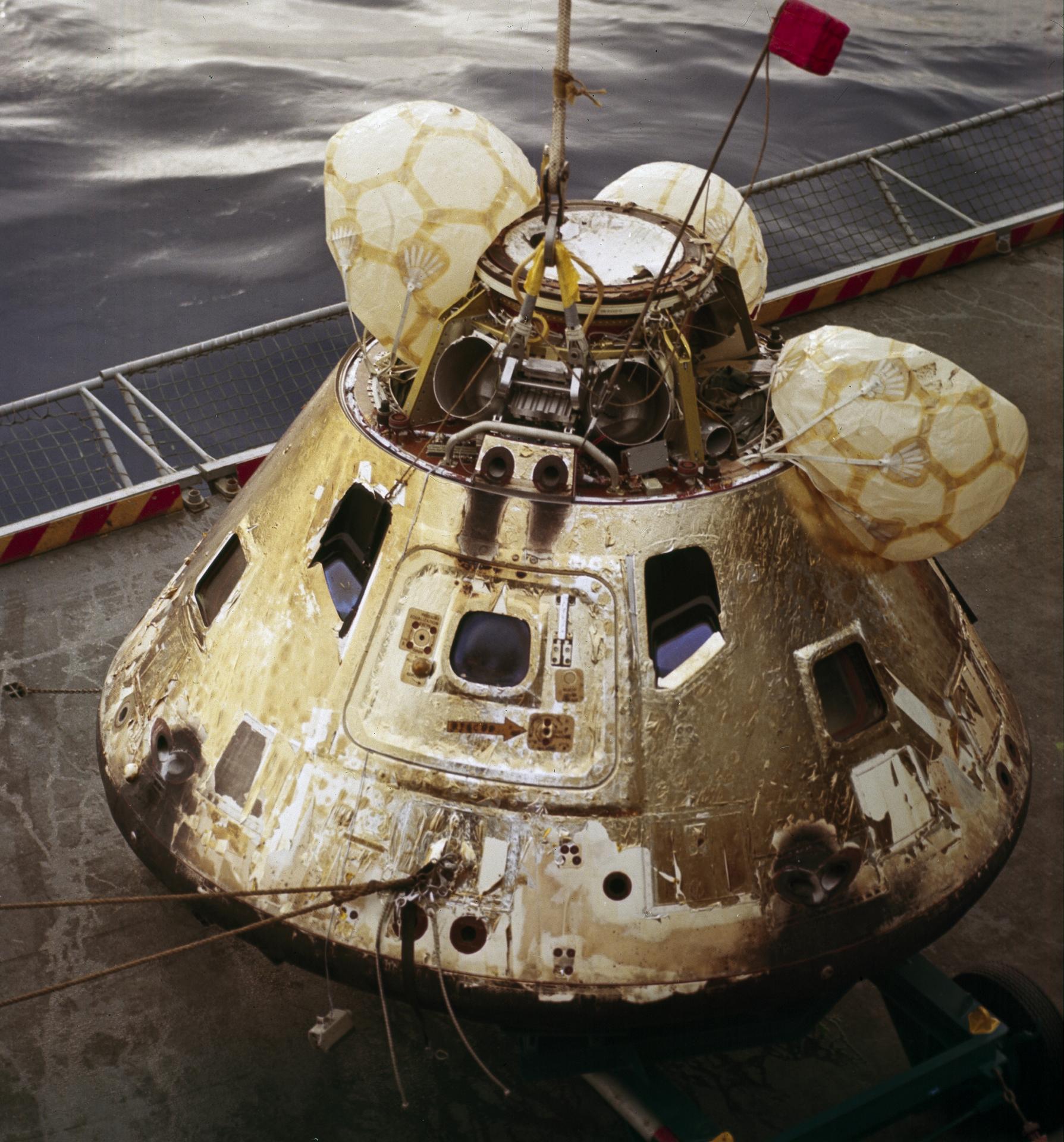
The bottom of the Orion capsule, which will be pointed into the heat as Orion returns to Earth, is covered by the world’s largest ablative heat shield, measuring 16.5 feet in diameter. The heat shield will protect Orion as it enters Earth’s atmosphere travelling about 25,000 mph and endure temperatures of nearly 5,000 degrees Fahrenheit— about as half as hot as the Sun. The outer surface of the heat shield is made of 186 billets, or blocks, of an ablative material called Avcoat, a reformulated version of the material used on the Apollo capsules. The Avcoat is bonded to a titanium skeleton and composite skin that gives the shield its shape and provide structural support for the crew module during descent and splashdown. During descent, the Avcoat ablates, or burns off in a controlled fashion, transporting heat away from Orion.
The crew module includes a number of mechanisms that provide the way to enter and leave the module through hatches. It also includes mechanism that provide docking capability for on-orbit activities with other spacecraft, as well as as mechanisms for the separation or jettison functions from other parts of Orion when the crew module needs to separate for entry and landing.
While the service module functions as the main propulsion system for Orion, the crew module has a propulsion system comprised of 12 small engines called reaction control system (RCS) thrusters that provide full control of module translation and rotation both on orbit and during entry. When the crew module separates from the service module for entry into Earth’s atmosphere, the 12 RCS thrusters control the spacecraft’s return.
The capsule also houses Orion’s parachute system that ensures a safe landing for astronauts returning from deep space missions to Earth. The system includes a series of 11 parachutes that are deployed in a sequence to slow down the module from speeds exceeding 25,000 mph to 20 mph or less and provide a safe speed for splashdown at landing.
Crew modules for Artemis missions are built by prime contractor Lockheed Martin, and primary structure welding takes place at NASA’s Michoud Assembly Facility in New Orleans. Orion piece parts and components are provided by hundreds of suppliers across the nation, and parts are delivered to the assembly facility located at the Kennedy Space Center. Orion is then outfitted with all these parts and internal components, assembled by teams at Kennedy, then transferred to the Exploration Ground Systems (EGS) team which performs final preparations on the spacecraft for launch.
Crew Module Quick Facts
| Height | 11 ft. |
| Diameter | 16.5 |
| Habitable Volume | 330 cu ft. |
| Pressurized Volume | 690.6 cu ft. |
| Lunar Payload Return | 220 lbs. |
| Artemis I Liftoff Weight | 20,500 lbs. |
| Artemis II Liftoff Weight | 22,900 lbs. |
| Artemis I Landing Weight | 18,200 lbs. |
| Artemis II Landing Weight | 20,500 lbs. |
| Engines/Thrusters | 12 Reaction Control System (RCS Thrusters) 160 lbs. of thrust each |
From an anthropomorphic standpoint, Orion is designed to accommodate 99 percent of the human population, which is a larger range than every other NASA or Department of Defense project past, present, or future. The spacecraft can accommodate astronauts as small as a 4-foot-10-inch tall female and as tall as a 6-foot-5-inch male.
Orion’s crew module provides about 60 percent more cubic volume of space than the Apollo capsule.
Orion can sustain a crew of four for up to 21 days in orbit during its initial missions to low lunar orbit. Missions to more distant destinations may have a crew of 2 to allow more room for consumables onboard.
Orion can orbit the Moon autonomously without any crew onboard for over six months.
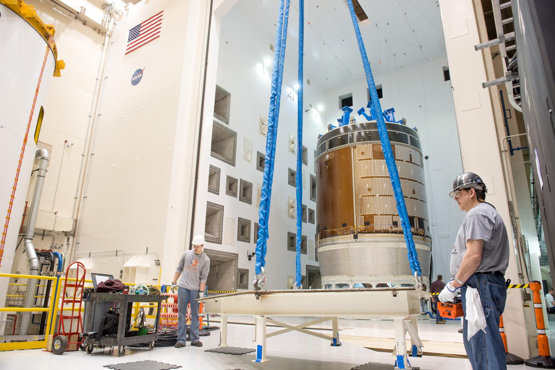
European Service Module
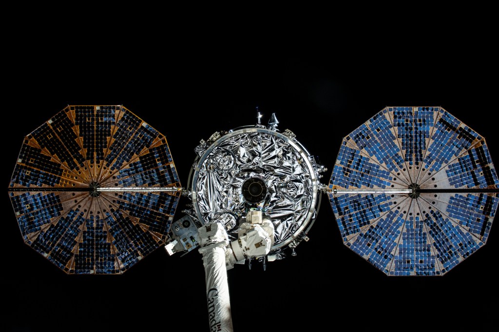
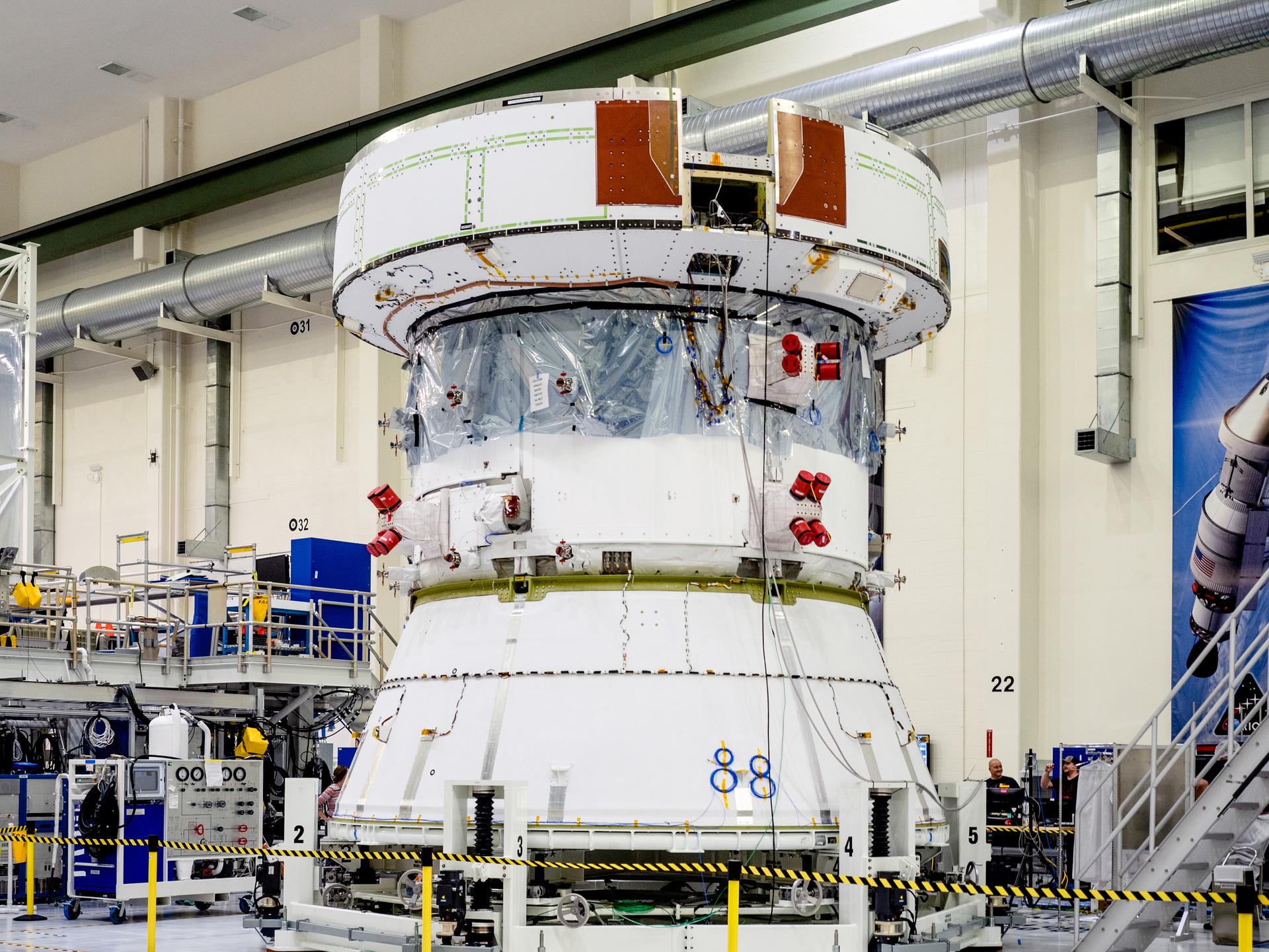
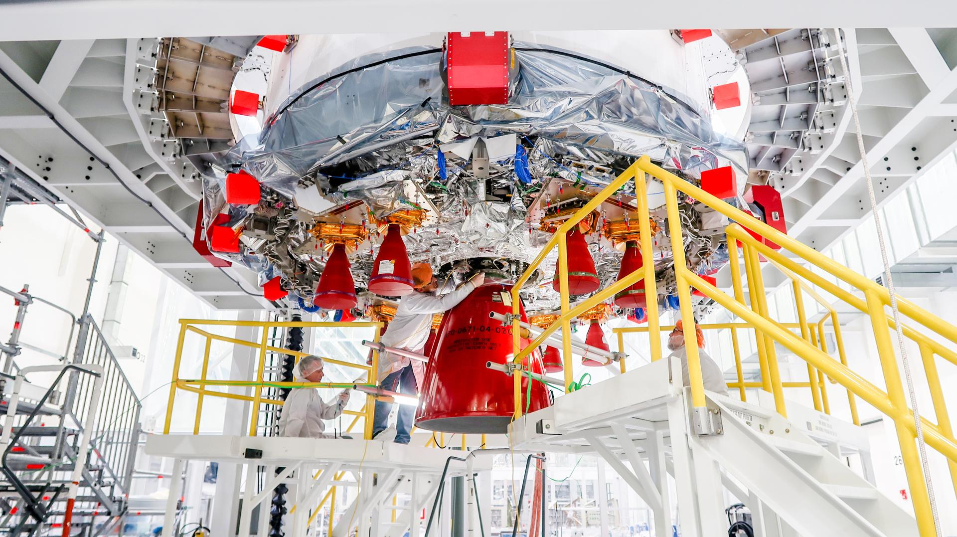
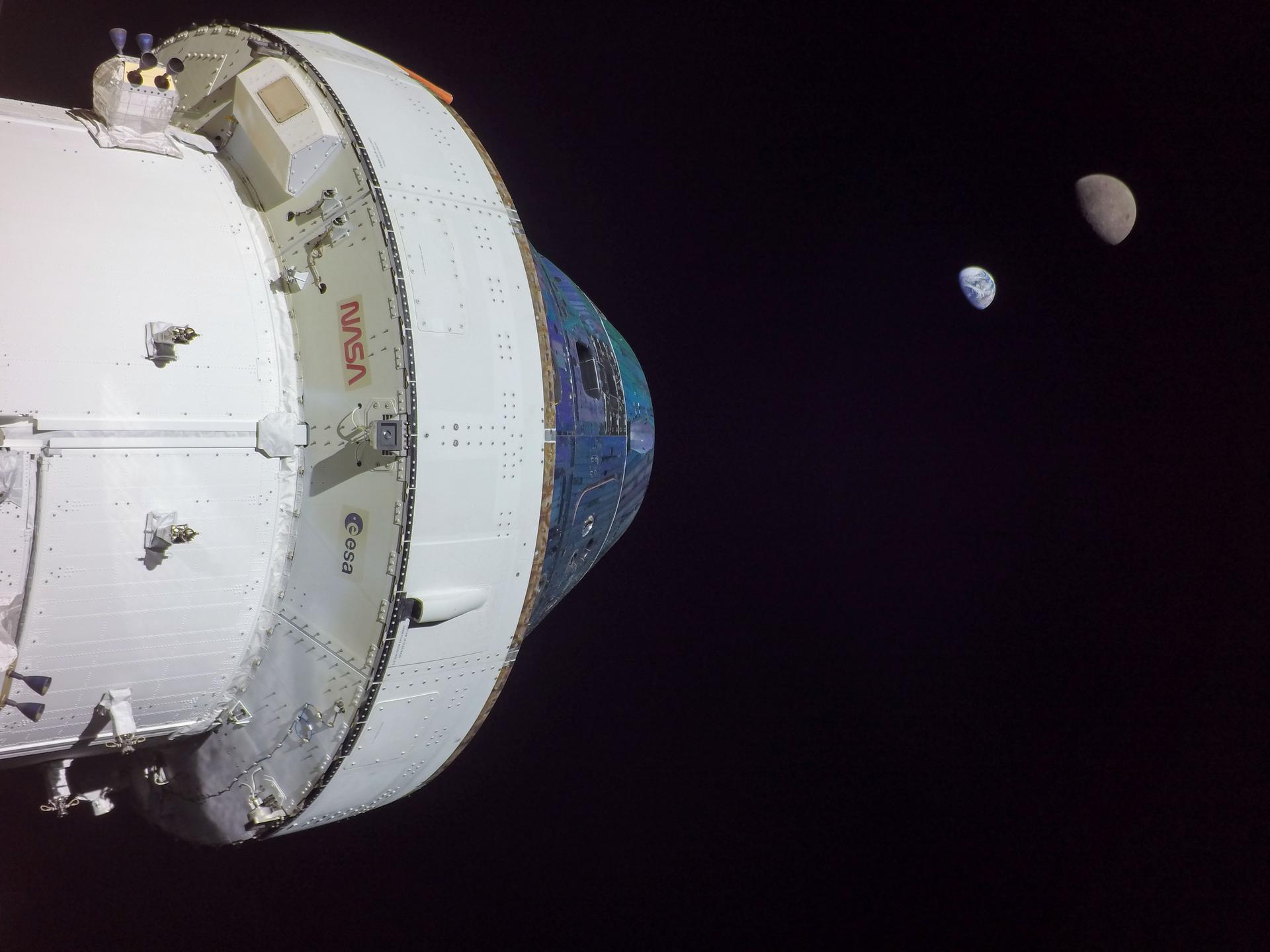
Orion’s European Service Module is the powerhouse that fuels and propels the Orion spacecraft in space. Located below the crew module, it provides critical functions including propulsion, thermal control, and electrical power generated by solar arrays. The service module will also provide life support systems including water, oxygen, and nitrogen for the crew. In addition to its function as the main propulsion system for Orion, it is responsible for orbital maneuvering and position control. The cylindrical module is unpressurised and about 13 feet high, including the main engine and tanks for gas and propellant, and is designed for long duration missions to deep space destinations.
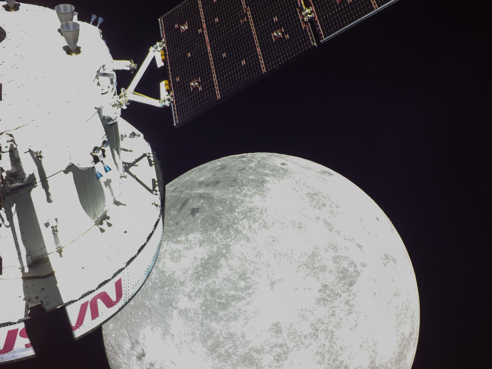
During launch, the service module fits into a 17-foot diameter housing, surrounded by three spacecraft adapter jettison fairing panels. The panels offer protection from harsh environments such as heat, wind, and acoustics during launch. Once Orion is above the atmosphere, the fairing panels surrounding the service module are jettisoned, and the solar arrays unfold to span about 62 feet. Following launch, Orion’s service module will propel the spacecraft on its mission and help it return to Earth, detaching before the crew module enters Earth’s atmosphere.
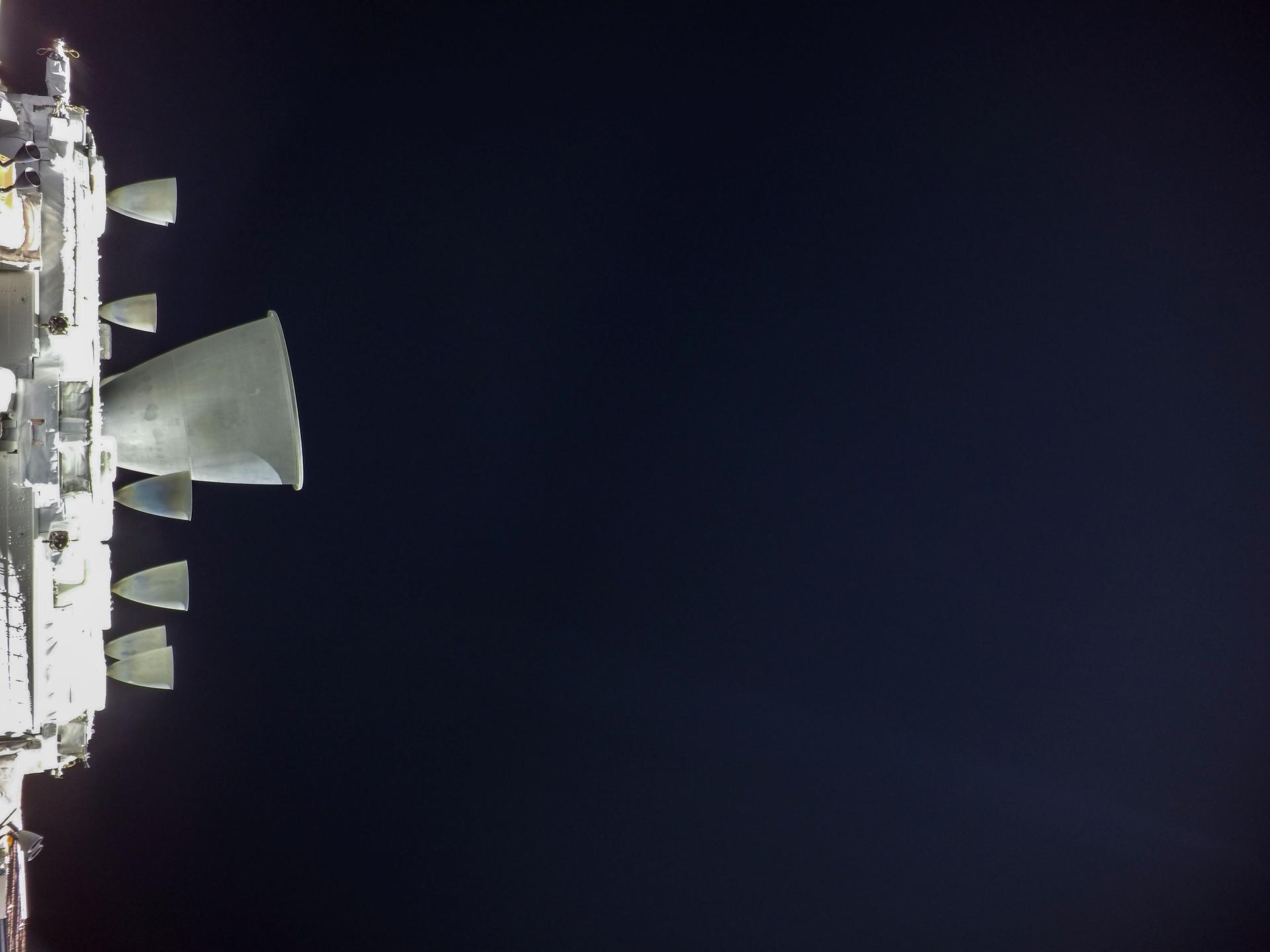
To push Orion to its destination, the service module is equipped with a total of 33 engines: one main engine (NASA-provided refurbished Orbital Maneuvering System engine (OMS-E); eight auxiliary engines (NASA-provided Aerojet R4D-11), and 24 reaction control thrusters (ESA-provided engines that are the same model as those used on the Automated Transfer Vehicle (ATV). These three types of engines provide the propulsion for lunar orbit injection and return to Earth, as well as attitude control for the crew module. The propulsion system can also be used, during some late phases of the launch, for crew safeguard during potential abort scenarios.
Built by Thales Alenia Space in Italy, the primary structure of the service module is the backbone of the entire vehicle. Like the chassis of a car, the structure holds everything together. It is covered with Kevlar to absorb shocks from micrometeorites and debris impacts.
During launch, the service module is held in place by the spacecraft adapter. The spacecraft adapter connects to the Orion stage adapter that attaches Orion to the SLS rocket.
A crew module adapter connects the capsule to the service module. The crew module adapter houses electronic equipment for communications, power, and control, and includes an umbilical connector that bridges the electrical, data, and fluid systems between the main modules.
Computers control all aspects of the service module. Avionics manage the powered equipment and the data exchange services based on instructions received from Orion’s flight computers in the crew module. Nearly seven miles of cables send commands and receive information from sensors.
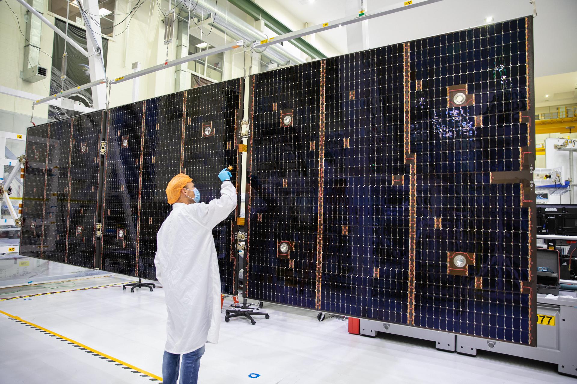
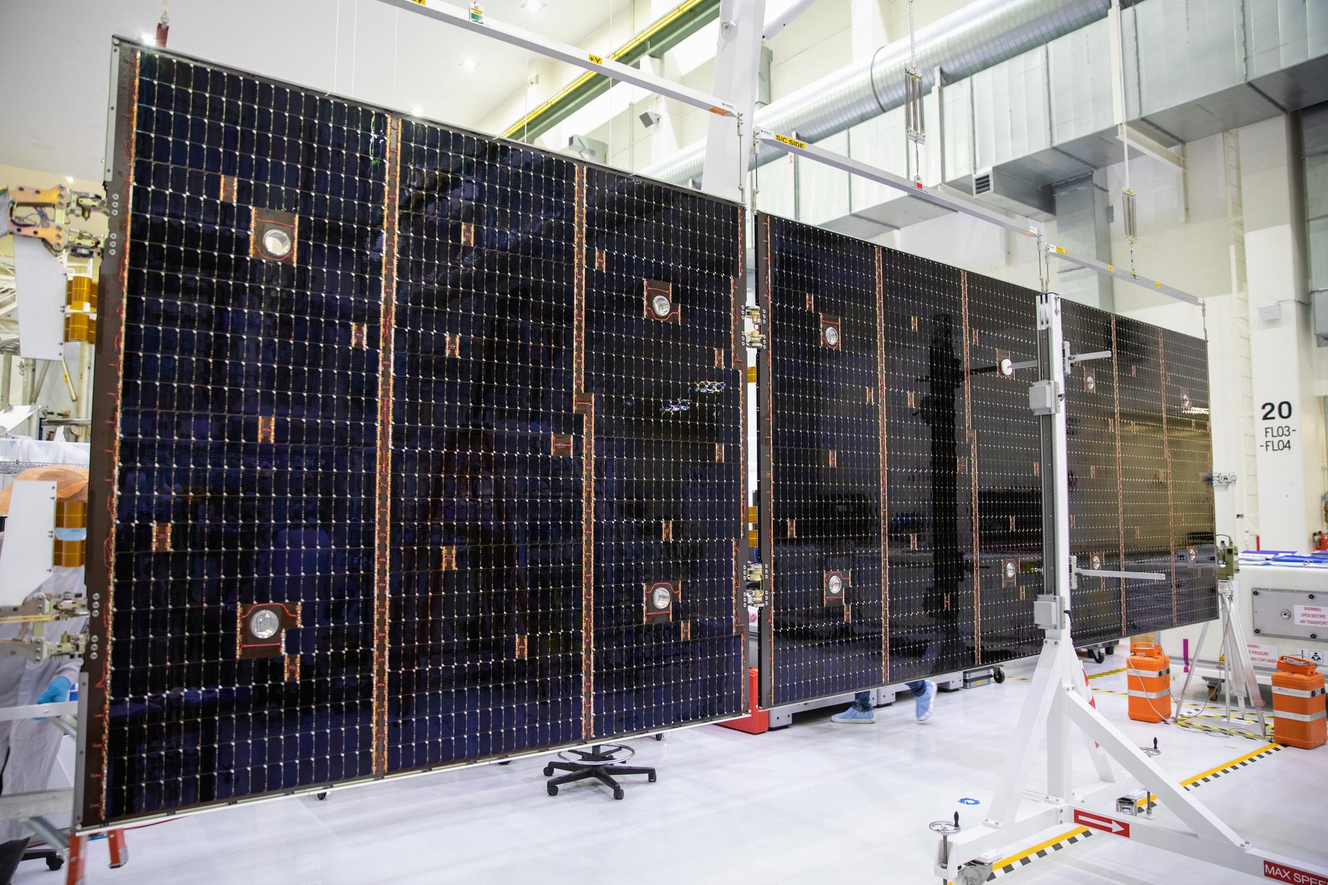
The service module’s electrical power system provides the power for the entire spacecraft. The system manages the power generated by the four solar array wings of the module. Each wing is made of three panels, and each panel is approximately 6.5 x 6.5 feet (2 x 2 meters). The total length of each wing is nearly 23 feet (7 meters). There are a total of 15,000 gallium arsenide cells on the four arrays used to convert light into electricity, and the arrays can turn on two axes to remain aligned with the Sun for maximum power. A power control and distribution unit provides the power interface between the service module and the crew module adapter, distributes electrical power to the service module’s electrical equipment, and protects the power lines. The module’s thermal control system includes radiators and heat exchangers to keep the astronauts and equipment at a comfortable temperature. The thermal control system includes an active portion, which transfers the heat of the entire vehicle to the service module radiators, and a passive portion, which protects the module from internal and external thermal environments.
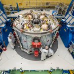
A consumable storage system provides potable water, nitrogen, and oxygen to the crew module. Potable water is provided by the water delivery system and stored in four metal bellow tanks, covering usable water needs of the crew for the duration of the mission. Oxygen and nitrogen are provided by the gas delivery system and stored in four tanks, the allocation of the tank to each gas being mission dependent.
The service module is built by main contractor Airbus under a contract for ESA (European Space Agency), with many companies across 10 European countries as well as the United States supplying components. Airbus has drawn on its experience as prime contractor for the ATV, which provided supplies to the International Space Station. The final product is assembled in Europe before being shipped to NASA’s Kennedy Space Center, where it is integrated with the rest of the Orion spacecraft.
Service Module Quick Facts
| Length | 15.7 ft. |
| Diameter | 16.5 ft. |
| Artemis I Weight | 33,700 lbs. |
| Artemis II Weight | 34,400 lbs. |
| Engine/Thrusters | 1 Orbital Maneuvering System Engine; 6,000 lbs. of thrust 8 Auxiliary Engines; 110 lbs. of thrust each 24 Reaction Control System Thrusters; 50 lbs. of thrust each |
| Solar Arrays | 4 arrays 15,000 solar cells 62 ft. when deployed 11kW regenerable electrical power |
The European Service Module is comprised of more than 20,000 parts and components that must fit together perfectly and perform reliably.
The computer in Orion’s service module controls 33 engines and reads over 100 pressure and temperature sensors.
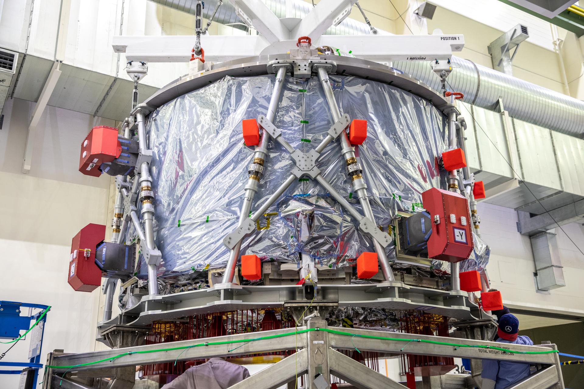
1,000 sensors collected data on Orion’s service module as it was vigorously shaken on a vibration table at NASA Glenn Research Center’s Neil A. Armstrong Test Facility in Sandusky, Ohio. This testing simulated how Orion’s structure flexed and stood up to 35 tons of spacecraft weight during a launch.
Each of Orion’s four solar array wings are made of three panels that provide enough electricity to power two three-bedroom homes.
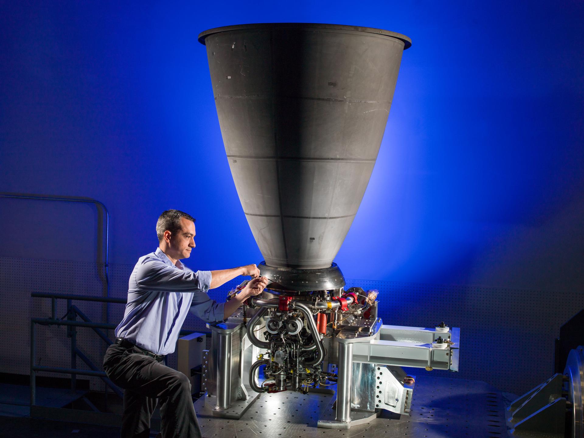
In space, Orion’s orbital maneuvering system engine, called the OMS-e, produces 6,000 pounds, or 26.7 kN, of thrust. Here on Earth, if you were to strap an OMS-e to a car, it would accelerate from 0-60 mph in approximately 2.7 seconds, ranking it among the world’s top 10 fastest production cars.
Orion’s service module main engine for Artemis I has been to space 19 times on three different space shuttles.
Avionics
The Orion spacecraft houses a number of state-of-the-art avionics units to handle data generated by on-board systems, control the various functions of the spacecraft, execute commands sent from Earth or by the crew, and return systems telemetry for insight into systems status.
The avionics and other electronics used in Orion are almost entirely driven by software and commercial processor technologies that have been ruggedized to endure extreme radiation and temperature fluctuations. Orion’s updated avionics also can handle the severe acoustic and vibration environments associated with launch, orbit, a fiery entry into Earth’s atmosphere, and a saltwater landing. Orion’s avionics system consists of seven main subsystems: command and data handling; guidance, navigation and control (GN&C); communications and tracking; displays and controls; instrumentation; power; and flight software (FSW).
Command and Data Handling
The brains of the Orion spacecraft consist of two vehicle management computers (VMC), manufactured by Honeywell. A VMC is a robust system that delivers more computing power to the Orion spacecraft than any
previous crewed spacecraft.
Each of the two VMCs is made up of two flight computer modules (FCM), which are in charge of executing flight control and other vehicle software, a display control module for astronaut displays, and a communication control module that allows commands and data to flow between Orion and mission control. The FCMs provide a high integrity platform to house software applications and have sufficient processing power to perform command and control of Orion. Each of the four FCMs are internally redundant and continually check all operations to be sure they match. If the FCMs ever detect a difference between them, due to a hardware failure or a radiation upset, the different FCM ‘fails silent’ by stopping all outputs so that a potentially corrupted FCM doesn’t issue critical commands to the vehicle. The FCM then resets itself, listens to the other FCMs to relearn where the vehicle is and what is happening, and then rejoins the other FCMs in controlling the vehicle – all within 22 seconds. Having four FCMs on the vehicle allows the flight software to continue firing thrusters and flying as Orion transitions through the challenging radiation environment of the Van Allen belts, since the odds of all four FCMs being upset in the same 22 seconds are extremely low.
The four redundant FCMs greatly improve system reliability, yet Orion adds another measure of backup capability with the addition of a completely different computer, capable of running different code should it ever be needed. In the unlikely event that something goes wrong with the primary flight computers on Orion, a dissimilar processing platform with dissimilar flight software is hosted on the vision processing unit (VPU). This dissimilar computer and software provide a backup function to the redundant FCMs during critical phases of flight, with a focus on crew survival and return functions in the highly unlikely scenario where anything renders all the FCMs ineffective. The VPU also provides a place to store data during times when Orion can’t communicate with the ground.
Eight power and data units (PDU) connect the flight computers and the software to the rest of Orion. These PDUs control the power to every component on the vehicle and they control effectors such as valves, thrusters, and heaters. All sensor data such as temperature and pressure are routed through the PDUs as well. The PDUs also play a critical role in communicating with the rocket that launches Orion and puts it on its trajectory to the Moon.
Orion’s onboard data network is a triple redundant network that allows the FCMs to communicate with all of the other avionic components on Orion. It uses a networking technology called Time-Triggered Gigabit Ethernet (TT-GbE) that is capable of moving data at a rate 1,000 times faster than systems used on the shuttle and space station. The TT-Gbe allows NASA engineers to categorize different types of data and prioritize how it should travel through the onboard network. Time-critical data relating to vital systems like navigation and life support, called time-triggered data, has guaranteed bandwidth and message timing to ensure it is always delivered exactly on time. Data that is critical for delivery but not timing, such as file transfers, is called rate-constrained data and is sent immediately whenever time-triggered data is not present. Data used for non-critical tasks such as crew videoconferencing is delivered over the remaining bandwidth. The technology means that critical data and non-essential data can travel safely over a single network onboard a spacecraft for the first time. It is built upon a reliable commercial data bus that has been hardened to be resilient to space radiation and proven on the Orion Exploration Flight Test-1 (EFT-1). The data system interfaces with all components, including the European Service Module, through radiation hardened network switches.
Guidance, Navigation, and Control
The guidance, navigation, and control (GN&C) system is responsible for always knowing where the spacecraft is and where it is going, and controls the propulsion system to keep Orion pointed in the proper direction and on the correct trajectory.
At the center of this system is the GN&C flight software (FSW) that executes on the VMCs. This software receives inputs from navigation sensors and pilot controls and commands the appropriate effectors on the crew module, service module, and launch abort system to accomplish mission objectives. The Orion GN&C software operates across a variety of mission phases, including pre-launch, ascent, Earth orbit, transit to and from the Moon, loiter, rendezvous, docking, entry, and various abort scenarios. The software must operate in both manual and automated modes, and must handle commands from the crew and the ground. The software must also execute complex guidance and navigation algorithms while controlling highly dynamic configurations during entry, ascent aborts, and orbital maneuvers. The resulting range of algorithm types drives a multi-rate architecture to meet central processing unit usage allocations.
The onboard navigation system for Orion is comprised of a number of redundant sensors for measuring Orion’s position (where Orion is in space) and attitude (what direction the spacecraft is pointed). Like most systems on the spacecraft, there are usually at least two of each sensor to increase reliability of the overall system. Because the spacecraft operates in the atmosphere during ascent and entry, in low Earth orbit, and near the Moon, several different types of sensors are needed. These include:
- Orion Inertial Measurement Units (OIMU): Each OIMU contains three rate gyros which measure vehicle body rotation rates and three accelerometers to measure vehicle body accelerations. This inertial data is used by the VMC for onboard navigation to compute spacecraft position, velocity, and attitude.
- Global Positioning System (GPS) Receivers: Similar to ground-based GPS, except these are capable of operating at the very high velocities of spaceflight. The GPS sensor system provides position and velocity updates during low Earth orbit operations, ascent, and entry. Because the GPS satellites point toward the Earth, GPS can’t be used out near the Moon. GPS-based altitude values are the primary triggers for entry events.
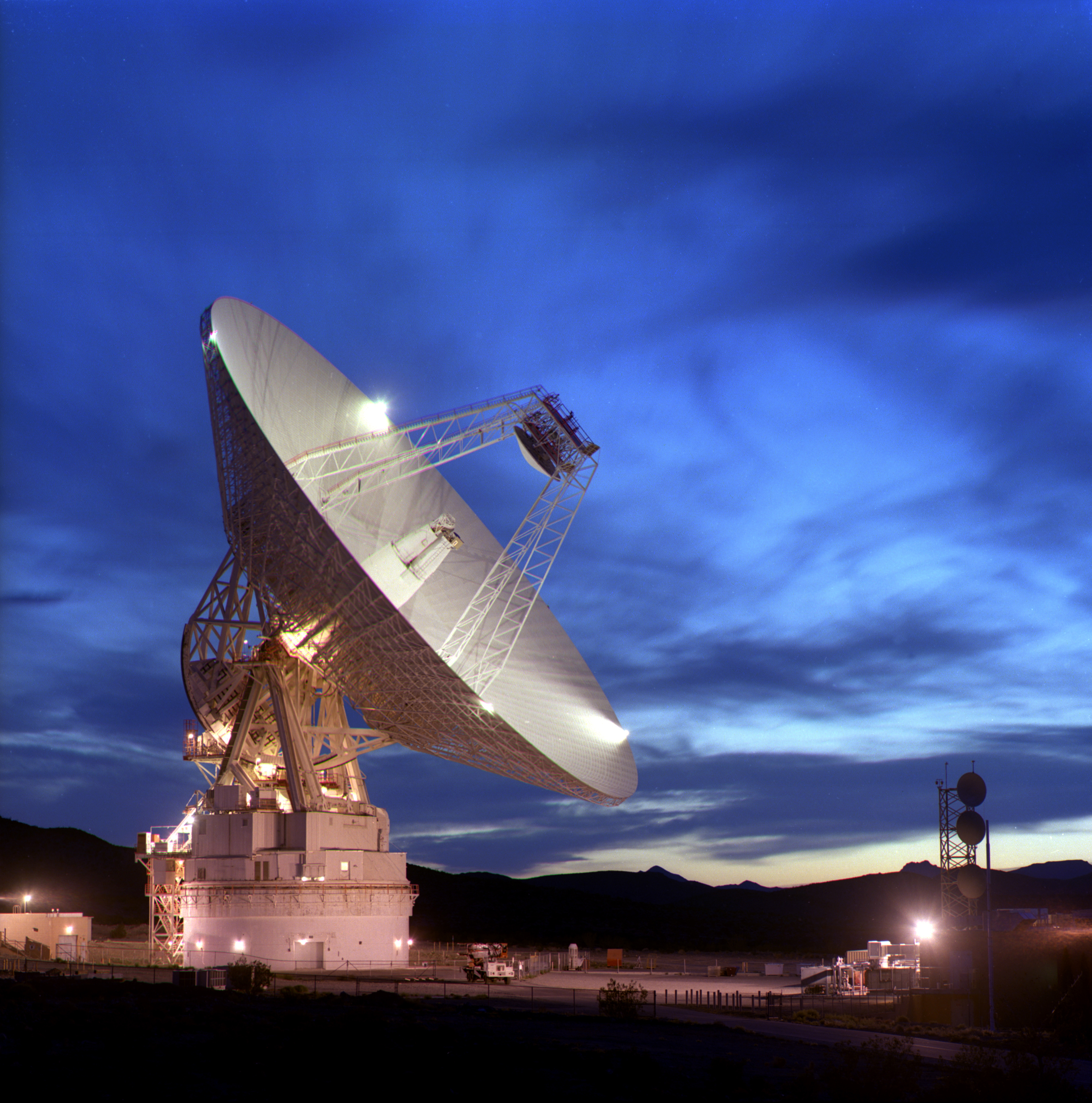
- Deep Space Network (DSN): This is not an on-board system, but instead a ground-based network of large tracking dishes all around the world that together can determine Orion’s location while it is in deep space outside the range of GPS. It relies on very sensitive timing of measurements of communication signals that pass between Orion and the dishes on the ground.
- Barometric Altimeter Assembly (BALT): By sensing the atmospheric air pressure outside the spacecraft during ascent and entry, these assemblies can measure Orion’s altitude. They provide a back-up altitude value for parachute and other deployments during entry.
- Star Trackers (STR): The star tracker operates like a camera but is very sensitive and takes pictures only of stars. By comparing the pictures to a known star catalog, the sensor determines spacecraft attitude during orbital operations.
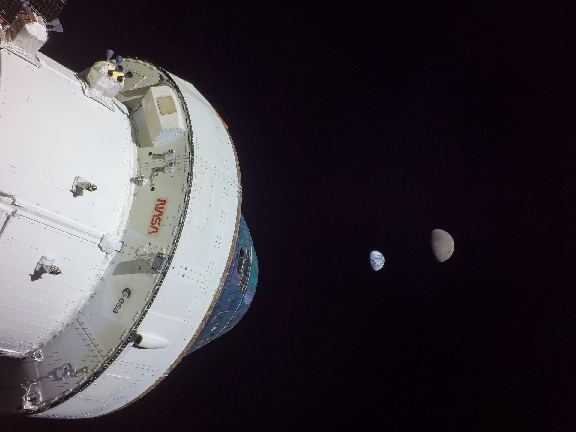
- Optical Navigation (OpNav) Camera: The OpNav camera takes images of the Moon and the Earth. By looking at the size and position of these objects in the picture, OpNav can determine Orion’s range and bearing to that object. OpNav is part of the Orion emergency return system to autonomously operate the vehicle in the event of lost communication with Earth.
- Sun Sensors: The Sun sensors are located on the ESA-provided service module and are used to determine the direction of the Sun during emergency safe mode. Knowing where the Sun is ensures that Orion can point its solar arrays in the right direction to keep power flowing.
Communications and Tracking
Orion uses a high-speed communications system, employing four phased array antennas on the crew module and two phased array antennas on the service module. Phased array antennas allow signals to be controlled and directed without requiring any physical movement of the antenna. These will be used for video, data, and voice communications with the spacecraft, as well as command uplink and telemetry downlink to ground stations, NASA’s Tracking and Data Relay Satellite Systems, and NASA’s Deep Space Network after leaving Earth’s orbit. The crew will also have an emergency radio system to allow voice communications anytime during a mission if the main communications system were to fail. After landing, the crew has search and rescue radios as well as satellite phones for communication with recovery forces. There is also an audio system on board that allows astronauts to speak with each other and with the ground while they are wearing spacesuits.
Orion also has a number of cameras inside and outside of the vehicle to help the crew with tasks like docking, interviews and public outreach events, medical conferences, and to help gather engineering pictures and video to make sure the spacecraft is performing properly. Each of the solar array wings has a wireless camera near the tip that can be pointed to inspect the exterior of the spacecraft and to provide some views that are out of this world.
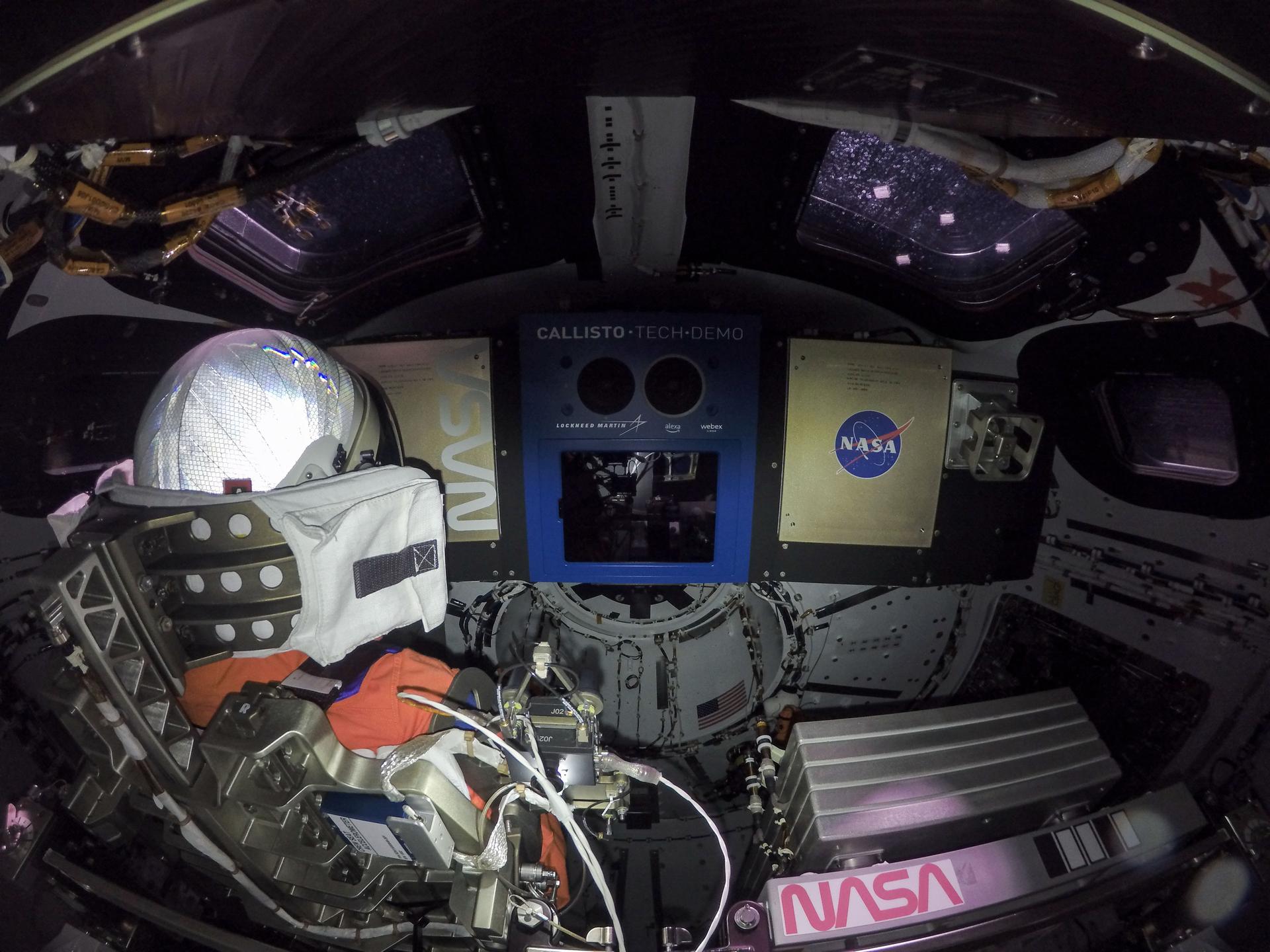
Displays and Controls
The Orion displays and control equipment is the crew interface to the Orion systems. The displays and controls consist of three display units, seven switch interface panels, two rotational hand controllers, two translational hand controllers, and two cursor control devices. The switch panels and hand controllers’ hardware interfaces through serial interfaces to the power and data units, then via the onboard data network to either flight control modules or the display units for processing. The display units utilize a variety of display formats to provide data to the crew for awareness and action when necessary.
The Orion displays and controls are designed for an intensive amount of crew interaction both in nominal and off-nominal scenarios. Electronic procedures have been developed for Orion that allow direct interaction with the display formats enabling reduced workload on the crew. The electronic procedures efficiently step the crew through planned tasks and reduce crew workload by highlighting various telemetry on a display format or queuing up commands. Additionally, the electronic procedures have built in links to the onboard caution and warning system which alert the crew when onboard faults and anomalies occur. The electronic procedures link provides the ability for the crew to bring up electronic procedures which communicate the urgent actions the crew need to take in order to address the caution and warning condition.
Power
The Orion power system is capable of generating and supplying all of the power that is required for its on-orbit operations. The four Orion solar arrays are located on the European Service Module, generate about 11 kilowatts of power and spread 62 feet when extended. Orion’s four main batteries are located on the crew module and use small cell packaging technology to ensure crew safety while providing 120 volts of power to the many systems on Orion. The batteries are fully charged before launch to operate the spacecraft until the solar arrays can be deployed once in orbit. The batteries also operate the spacecraft when the solar arrays cannot be pointed at the Sun or in the shadow of the Earth or the Moon. The solar arrays are jettisoned right before entering the Earth’s atmosphere, so the batteries also provide all the power needed to keep the astronauts safe for return to Earth and up to 24 hours after splashdown. Power is transferred between the solar arrays and batteries and to the end item loads via the power and data units.
Instrumentation
Accomplishing flight test objectives for the flight tests requires a dedicated instrumentation system that will measure dynamic response of all Orion subsystem performance during critical phases of the Artemis missions. These include structural response and thermal protection system response during entry into Earth’s atmosphere. A suite of avionics data acquisition system electronics along with associated cabling supports the large number of channels needed.
The developmental flight instrumentation (DFI) data system is required to measure unique subsystems performance during all phases of flight from launch, cruise, and return to Earth. The DFI diagnostic instrumentation system is required to measure the response of newly designed components and structures to verify and validate engineering models that will be used to predict their future performance.
The architecture of the DFI system is very robust and relies on proven hardware and software to deliver high reliability. The central components are data acquisition units which have two interfaces: one for the sensor interface, and one for the control interface. The sensor interface communicates with the temperature, strain, accelerometers, and acoustic sensors. The control interface in turn communicates with the power, control, recording, telemetry, and time-sync hardware. The sensors can be changed between flights to allow engineers to make adjustments based on what is learned about a previous flight.
Compared to Apollo's single flight computer, Orion has two simultaneously operating redundant flight computers. Each of these includes two redundant computer modules, giving it a total of four redundant systems.
One of Orion's two redundant computers is only three quarters the weight of the sole computer aboard Apollo.
One of Orion’s two computers also has 128,000 times more memory and is 20,000 times faster than Apollo’s computer. Orion’s computing redundancies not only improve safety, they also improve data collection and processing power.
Orion’s avionics system, which helps control things such as navigation and communication, has some parts as small as the head of a pin.
The Orion power system can control power to over 200 components and over 700 heaters across the spacecraft.
The Orion Gigabit Ethernet is 1,000 times faster than shuttle networks.
Orion’s ‘glass’ cockpit provides fully redundant crew controls and displays with over 60 graphical user interface, or GUI formats and interactive electronic procedures – a first in spacecraft history. Instead of relying on physical switches distributed across a vast flight deck, an astronaut will be able to control all of the vehicle systems from a single operator station using 'virtual' switches displayed on GUIs.
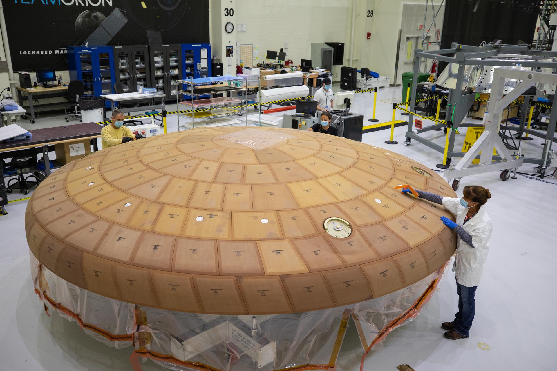
Heat Shield
The heat shield is one of the most critical elements of the Orion spacecraft, protecting Orion and the astronauts as they enter Earth’s atmosphere travelling about 25,000 mph and reaching temperatures of nearly 5,000 degrees Fahrenheit — about as half as hot as the Sun.
Measuring 16.5 feet in diameter, it’s the largest ablative heat shield in the world. The outer surface is made of blocks of an ablative material called Avcoat, a reformulated version of the material used on the Apollo capsules. During descent, the Avcoat ablates, or burns off in a controlled fashion, transporting heat away from Orion.
The Avcoat is first made into large blocks at NASA’s Michoud Assembly Facility, then shipped to NASA’s Kennedy Space Center in Florida and machined into 186 unique shapes before being applied onto the heat shield’s underlying titanium skeleton and carbon fiber skin. Engineers conduct non-destructive evaluations to look for voids in the bond lines, as well as measure the steps and gaps between the blocks. The gaps are filled with an adhesive material and then reassessed.
After the thermal protection system has been applied and inspected, engineers and technicians put the heat shield through a thermal cycle test in the high bay of the Operations and Checkout (O&C) Building at Kennedy. The thermal cycle test ensures the thermal protection blocks are properly bonded and will perform as expected when they are exposed to the extreme temperatures during the mission.
The heat shield is then given a coat of white epoxy paint. Aluminized tape is applied after the painted surface dries to dissipate electrical surface charges and maintain acceptable temperatures. Once all testing has been completed, the heat shield is bolted to the crew module.
The Orion heat shield was redesigned from a single piece system to individual blocks of material following Exploration Flight Test-1 in 2014. Before the time-saving block system was used, a fiberglass-phenolic honeycomb structure was bonded to the structure’s skin. Then each of the 320,000 tiny honeycomb cells were individually filled with Avcoat by hand, inspected by X-ray, cured in a large oven, and robotically machined to meet precise thickness requirements.
This new design introduced several considerations that prompted further testing for risk reduction. Engineers performed more than 30 tests across the United States on the new design to investigate the effects of the block structure that could disrupt the smooth airflow and cause localized heating spots. Understanding both effects is critical to confirm the heat shield will thermally protect the astronauts during entry into Earth’s atmosphere. The Avcoat material was tested at the NASA Ames Research Center Arc Jet Complex and at the NASA Johnson Space Center’s Atmospheric Reentry Materials and Structures Evaluation Facility through its closing in 2014. The Arc Jet facilities were used to simulate the heating and airflow conditions that occur during entry. Thermal testing also has been performed at Johnson Space Center’s Radiant Heat Test Facility (RHTF) periodically from the onset of the Orion Program up until March 2021. During these tests, the Avcoat surface reached temperatures of over 3,000 degrees Fahrenheit. Heat shield testing concluded in March 2019 at NASA’s Langley Research Center with a six-inch Orion heat shield model in the 20-inch Mach 6 wind tunnel. The six-inch Orion heat shield model was machined to represent small-scale features, including the patterns expected as the heat shield ablates during return to Earth.
Backshell Panels
Orion’s backshell panels and forward bay cover will also provide protection from the excessive heat of entry into Earth’s atmosphere, as well as the micro-meteoroid debris which could be encountered during missions. There are 1,300 thermal protection system tiles made of a silica fiber material called AETB-8 (Alumina Enhanced Thermal Barrier). The tiles are similar to those used for more than 30 years on the space shuttle, and incorporate a stronger coating called “toughened uni-piece fibrous insulation,” or TUFI coating, which was used toward the end of the Space Shuttle Program. On average, the tiles are 8-inches by 8-inches and many are standard in size allowing them to have the same dimensions with the same part number.
During return to Earth from a mission to the Moon, Orion and its heat shield must protect the vehicle and crew from external temperatures up to around 5,000°F.
5,000°F is hotter than the melting point for titanium, which is about 3,000°F. It’s also about half the surface temperature of the Sun, which is about 10,000°F.
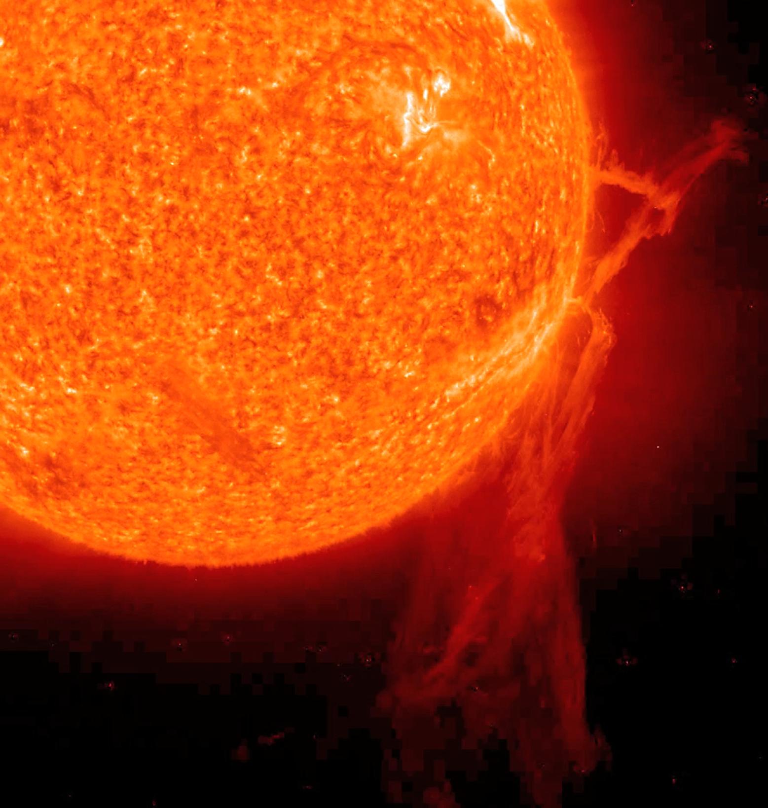
While the outside temperatures during entry into Earth’s atmosphere will reach 5,000°F, inside the spacecraft it will be in the mid-70s – hotter than molten lava on the outside and cool as a cucumber on the inside.
The heat shield on the bottom of the crew module is 16.5 feet wide. It is the largest ablative heat shield in the world. Orion’s thermal protection system is one of the most important parts of the spacecraft and is responsible for protecting the astronauts during their return.
Crew Systems
Orion has been specially designed and tested to make sure astronauts can live and work safely in the capsule during multi-week Artemis missions. Countless details inside and outside the spacecraft are meticulously thought through to ensure that astronauts are protected during anything they may encounter. From life support to spacesuits to crew accommodations, engineers have worked hard to evaluate and improve Orion’s features so that astronauts can complete missions in deep space comfortably, efficiently, and safely.
Environmental Control and Life Support Systems
On Orion, environmental control and life support systems (ECLSS) will make the crew module a habitable, safe place for astronauts and is key to survival as they travel on deep space missions.
On the International Space Station, a safe return to Earth is only hours away, but that is not the case for deep space missions. Orion provides an ECLSS that is fault tolerant and less complex than previous NASA human spacecraft. The key components of the ECLSS include atmosphere revitalization, pressure control, crew water supply, and crew waste management. For Orion, these systems must be mass and volume efficient as well as dependable.
Atmosphere revitalization is the highest priority on deep space missions. Systems must not only provide oxygen and remove carbon dioxide from the atmosphere, but also prevent gases like ammonia and acetone, which humans emit in small quantities, from accumulating. They also must provide adequate ventilation for the crew and filter particles and microbes. Orion has a new carbon dioxide and humidity removal system which is regenerable, a key for saving mass and volume on deep space vehicles. The system, when exposed to the cabin air, absorbs carbon dioxide and humidity. When exposed to the vacuum of space, the carbon dioxide and humidity are vented overboard, and the system is regenerated back to a clean state to return to cleaning the cabin air. On other human spacecraft such as the space shuttle, a method using expendable chemicals was used to remove carbon dioxide. For perspective, these chemicals took up the volume of nearly 143 basketballs. Orion’s system will take up the space of only 16 basketballs and save over 100 pounds.
Orion uses high pressure oxygen and nitrogen tanks to provide the pressure control for the crew environment. Using these tanks simplifies the system to provide for greater reliability on deep space missions. The pressure control system can be manually operated by the crew if required in a severe situation.
A water supply system stores and distributes potable water to the crew for drinking, food preparation, and medical and hygiene needs.
Environmental monitoring maintains the spacecraft’s temperature, humidity and pressure, and detects when the spacecraft’s enclosed environment is compromised, causing it to become unsafe. For deep space missions, Orion has an integrated crew survival capability, using pressurized suits for several days in order to return the crew home safely in the event of a total cabin environment loss due to pressure or air contamination. Not since Apollo has this capability been required.
The ECLSS on Orion balance between the ever-present constraints of launch mass, volume, system fault tolerance, and reliability of resources to sustain astronauts and keep them safe in deep space.
Universal Waste Management System
Orion’s crew module has a new space toilet, called the Universal Waste Management System (UWMS), making the essential task of going to the bathroom easier for both women and men and reducing the ever-important mass and volume of the system to be launched into deep space.
Looking back, astronauts on Mercury, Gemini, and Apollo did not have toilets. They urinated into diapers and bags and brought their solid waste mixed with bactericide in bags back home. Skylab was the first American spacecraft with a toilet, followed by the space shuttle. The space shuttle toilet was a full size larger (about 12.3 cubic feet) and a massive system, using several separate motors and fans for operations.
Orion’s toilet operates in a similar way, using air flow to pull fluid and solid waste away from the body and into the proper containers, but is improved for the needed mass and volume constraints of deep space flight in Orion, and is more accommodating to female astronauts. Based on their input, the shape of the seat for solid waste and design of the funnel for urine has been changed, and they can be used simultaneously.
It’s also self-contained and compact at about 5 cubic feet in volume, thus approximately 60 percent smaller and lighter than the space shuttle toilet, easier to use, and increases crew comfort. A new automatic air flow feature helps with odor control, fewer control interfaces simplifies crew operations, and a more ergonomic design requires less clean-up and maintenance time, as do corrosion-resistant, durable parts.
Pre-treated urine, which prevents the generation of ammonia from the breakdown of the urine, is stored in a urine tank and then vented overboard each day by the crew much like the space shuttle. Solid waste is collected in fecal canisters, which the crew replace every few days, and stored in Orion for the 21-day mission. The canisters have filtered caps to control odor and gas build up generated within the cans.
What makes the UWMS universal is that it can easily integrate into different spacecraft and systems, keeping our astronauts healthy and safe as they live, work, and learn on Orion farther from Earth than ever before.
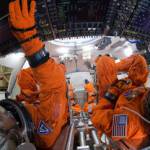
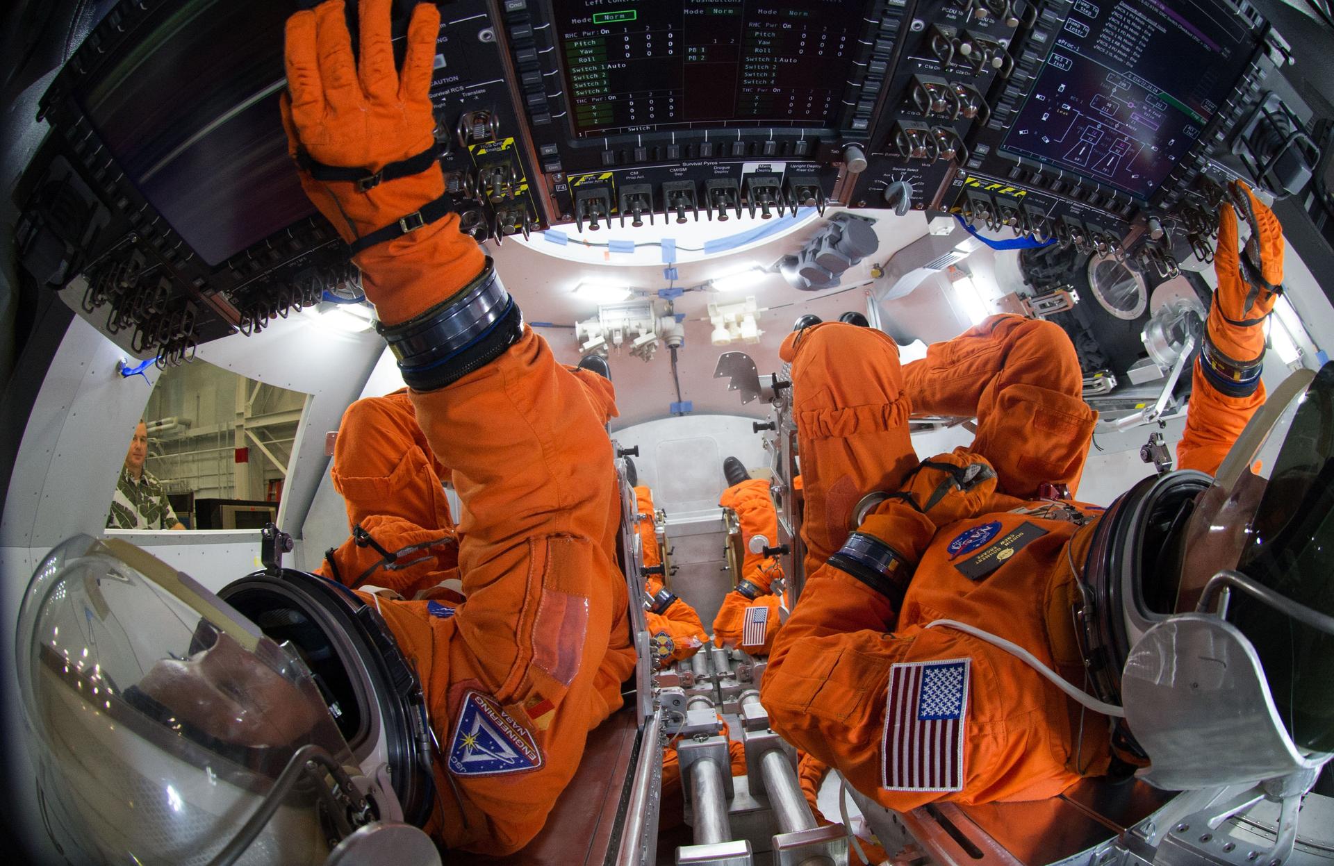
Orion Crew Survival System Suits
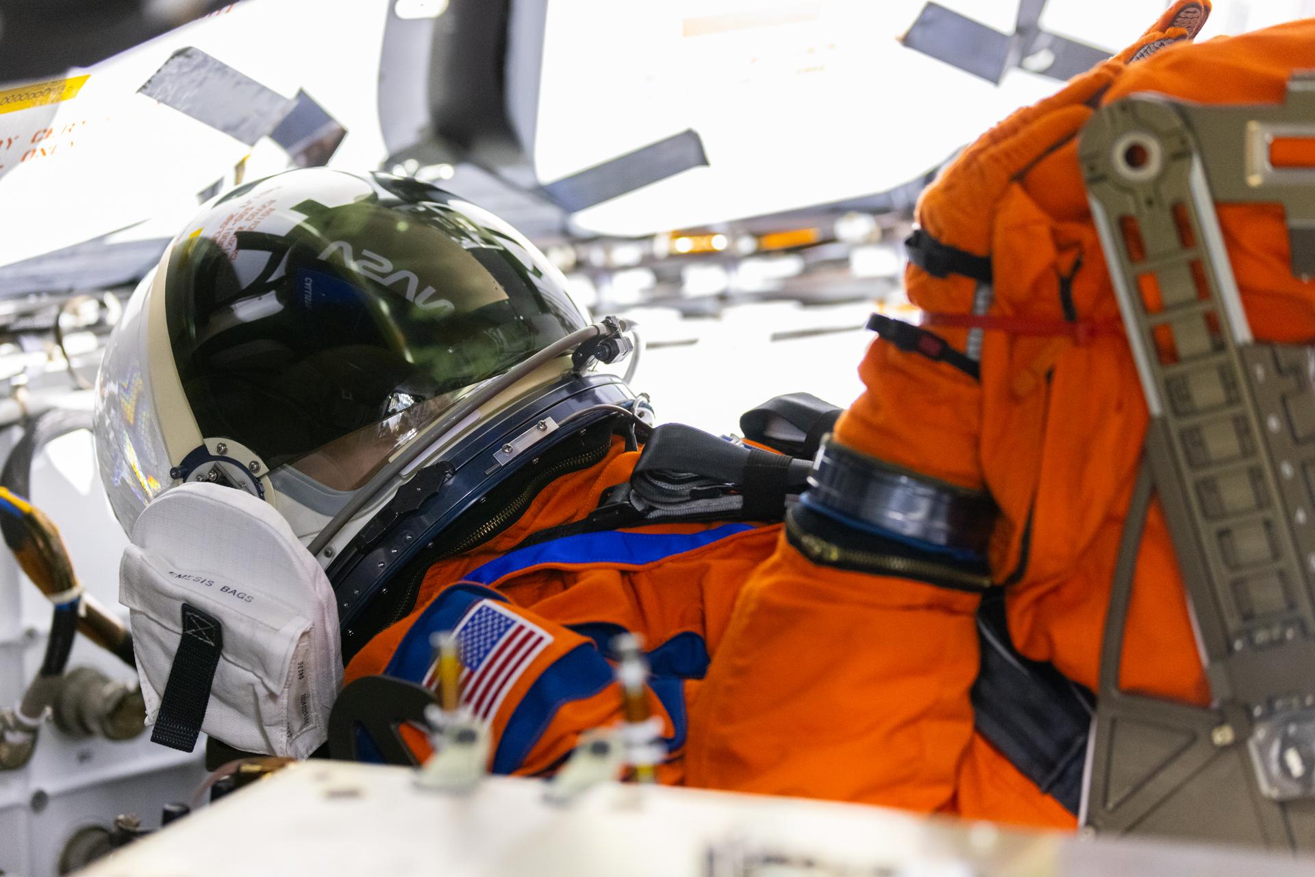
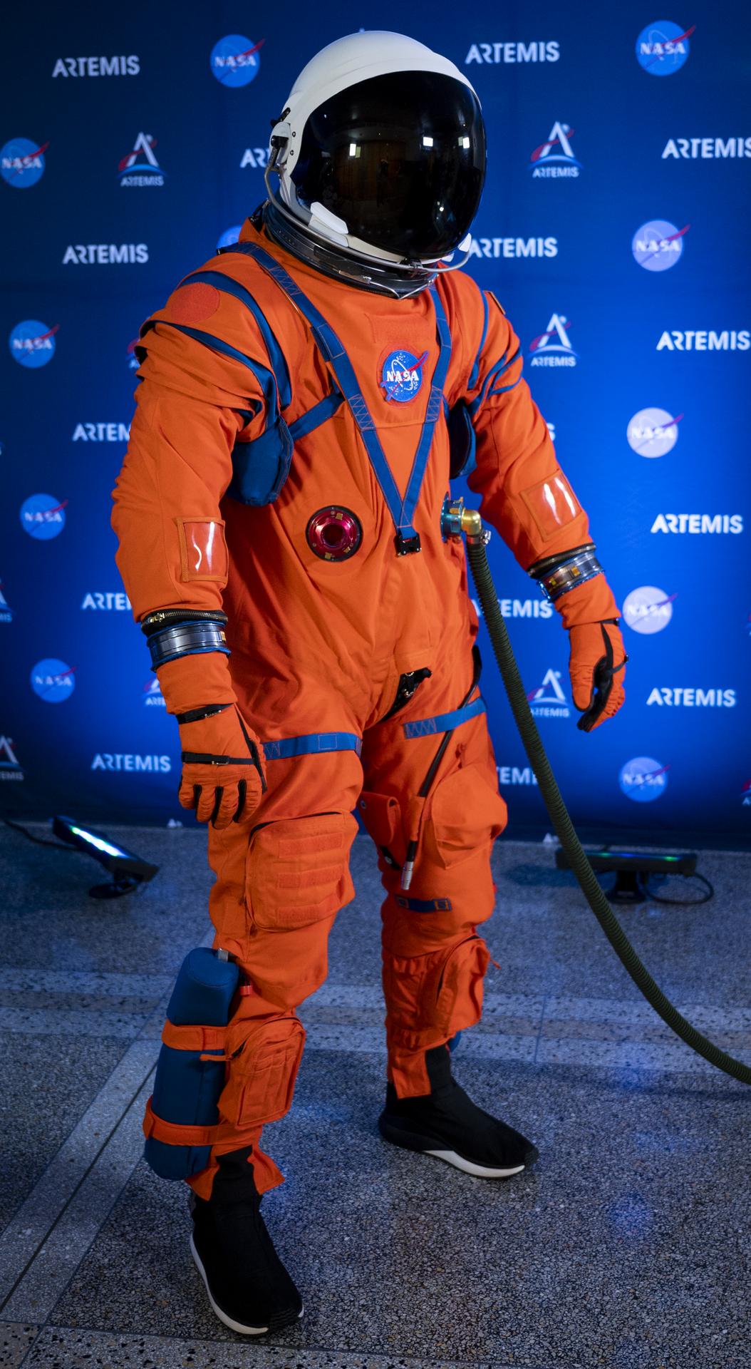
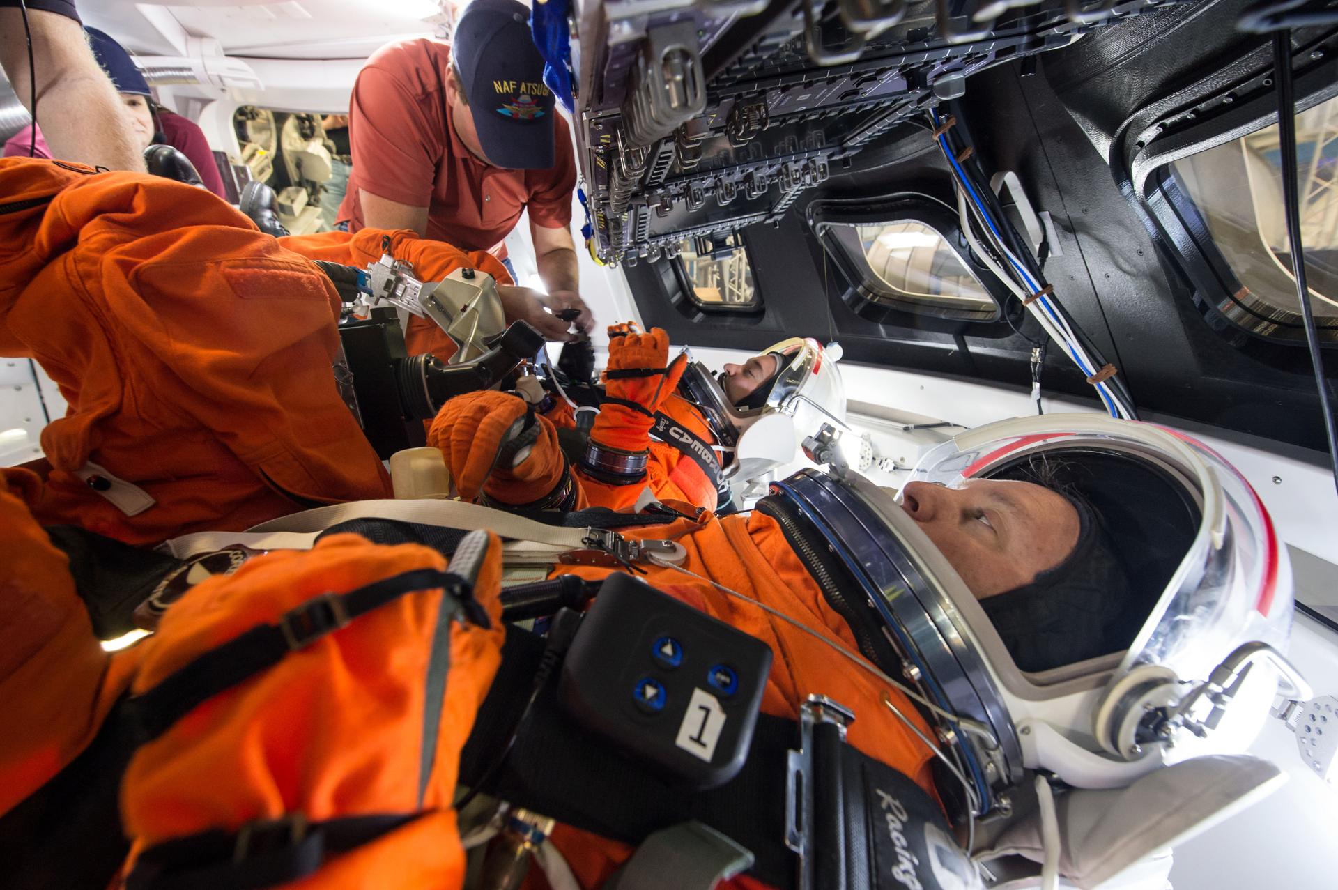
At several points during Artemis missions, astronauts will wear a bright orange spacesuit called the Orion Crew Survival System (OCSS) suit, which is designed to protect them on their journey.
Improvements have been made from head to toe to the suit worn on the space shuttle for Orion. Elements have been reengineered to improve safety and range of motion for astronauts, and instead of the small, medium, and large sizes from the shuttle era, they will be custom fit for each crew member.
The suits can keep astronauts alive for up to six days if Orion were to lose cabin pressure during its journey, with interfaces that supply air and remove carbon-dioxide. They are also equipped with a suite of survival gear in the event astronauts must exit Orion after splashdown in the ocean before recovery personnel arrive, and the color is easily recognizable in the ocean.
The outer layer is fire resistant and a stronger zipper allows astronauts to quickly put the suit on. Improved thermal management will help keep them cool and dry. A lighter, stronger helmet improves comfort and communication, and the gloves are more durable and touch-screen compatible. Better-fitting boots will also provide protection in the case of fire and help an astronaut move more swiftly.
Astronauts will wear the suit on launch day, in emergency situations, high-risk parts of missions near the Moon, and during the high-speed return to Earth. Its design and engineering enhancements provide an additional layer of protection for astronauts and ensure they return home safely from deep space missions.
Orion’s closed loop life support system is capable of maintaining a positive pressure, breathable atmosphere, and thermal cooling for up to 144 hours to suited crewmembers in the event of a pressure vessel leak or contaminated cabin atmosphere.
Orion is designed to execute an abort and return to Earth from any point in the mission regardless of orbital alignment with Earth, and provides a safe haven and survival equipment for onboard crew for up to 24 hours post-landing.
Orion is designed to provide assured crew return in the event of multiple system failures incorporating a backup flight computer, manual control of life support systems, communication, and navigation aids.
NASA and Lockheed Martin engineers working on the design of the Orion crew module collaborated with NASCAR and Indy Car racing experts specializing in crash injuries to design state-of-the art crew seats, restraints, and impact attenuation mechanisms to prevent injury of the astronauts in the event of a hard landing.