


![Request for Information – Potential [Placeholder for Prize]](https://assets.science.nasa.gov/dynamicimage/assets/science/psd/solar/2023/09/s/solarsystem_0.jpg?w=1024)


Launch Abort Motor Testing
The launch abort system motors are being rigorously tested before the first crewed launch of Orion on Artemis II. The abort motor, attitude control motor, and jettison motor have each completed final qualification testing. These tests look at the maximum high and low temperature conditions that a motor might see during a launch in Florida. They provide the data on how the motor reacts under hot or cold stressing conditions. All three motors were also flight tested during the Ascent Abort-2 demonstration in July 2019.
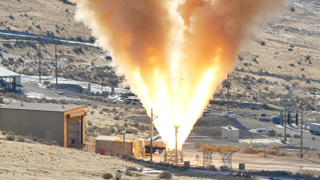
Abort Motor
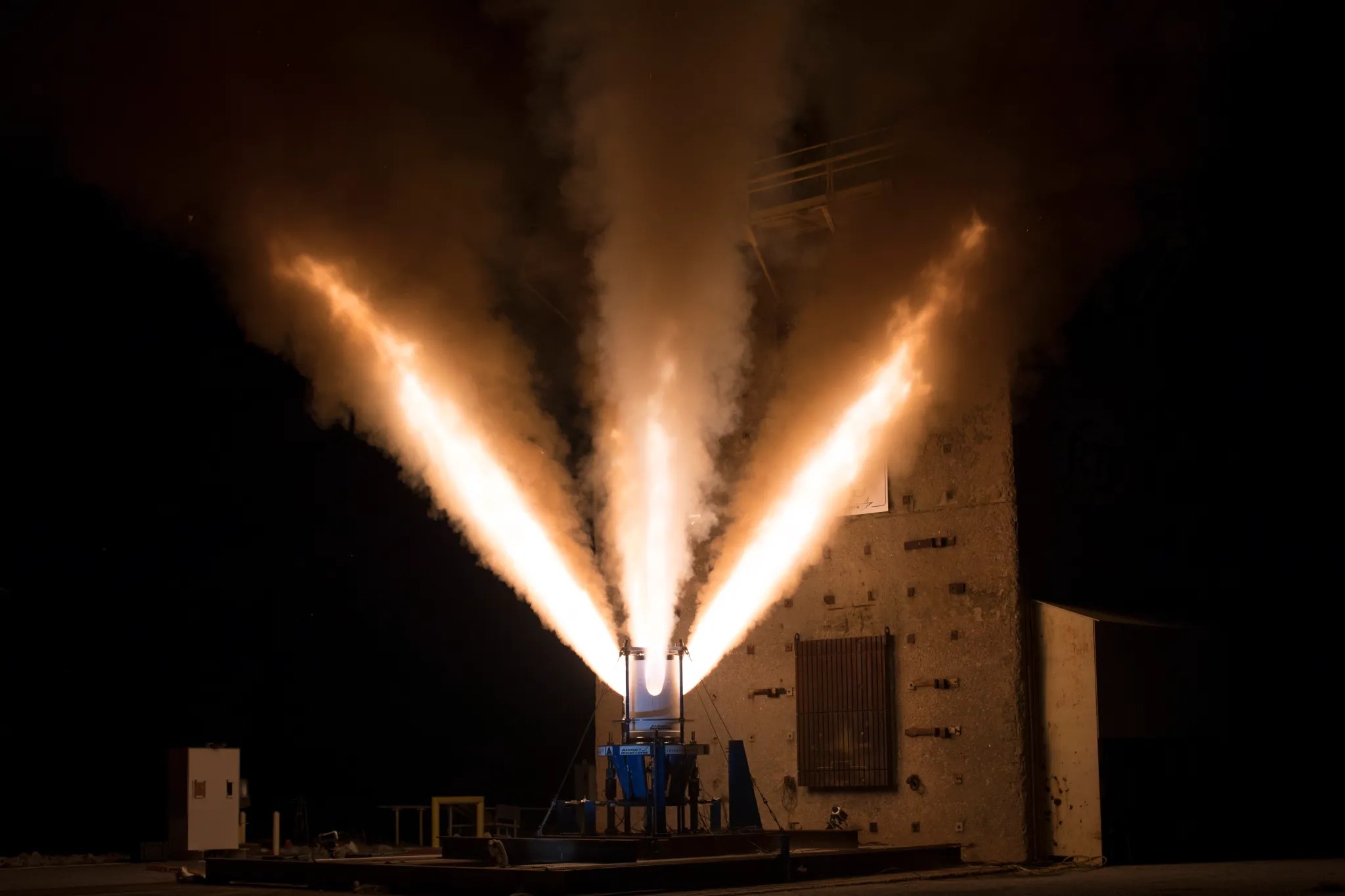
The 17-foot-long, three-foot-diameter abort motor has a manifold with four exhaust nozzles and provides thrust to quickly pull the crew module to safety if problems develop during launch. The high-impulse motor is designed to burn most of the propellant within the first three seconds and burns three times faster than a typical motor of this size to immediately deliver the thrust needed to pull the crew module to safety. If needed during a launch mishap, the crew module would accelerate from zero to 400-500 mph in two seconds. The motor was built by Northrop Grumman and tested at its facilities in Promontory, Utah.
During a series of static-fire tests, the motor was fastened to a vertical test stand with its nozzles pointed toward the sky. Upon ignition, the abort motor fired for five seconds with the exhaust plume flames reaching up to 100 feet in height. As expected, the motor reached approximately 400,000 pounds of thrust in one-eighth of a second – enough thrust to lift 66 large SUVs off the ground. The tests verified the motor can fire within milliseconds when needed and will work as expected under extreme temperatures.
Weight
7,600 lbs.
Includes 4,500 lbs. propellant
400,000 lbs. peak thrust
Fuel Type
Solid Fuel – hydroxyl-terminated polybutadiene (HTPB)
Burn Duration
About 3 sec.
The first test, called Qualification Motor-1 (QM-1), took place under high temperatures, with a target temperature of 100 degrees Fahrenheit. The test confirmed the system performed as intended under the maximum temperature conditions a motor might experience during a launch.
The second test, Qualification Motor-2 (QM-2), took place under cold temperatures, with a target temperature of 27 degrees Fahrenheit. The test confirmed the system performed as intended under the minimum temperature conditions a motor might experience during a launch.
The third and final test, Qualification Motor-3 (QM-3), took place under ambient conditions, or the conditions of the naturally surrounding environment. The test confirmed the system can perform as intended under average temperature conditions a motor might experience during a launch. The Orion program made a strategic decision to delay this test to incorporate new insulator material, called EPDM rubber. The high-performance rubber insulation is glued to the inside of the motor casing and the propellent is poured inside. Following this test, the LAS was officially qualified for flight with crew.
Abort Motor Testing in Promontory, UT
| QM-1 | June 15, 2017 | Hot Condition | 100°F |
| QM-2 | Dec. 13, 2018 | Cold condition | 27°F |
| QM-3 | March 31, 2022 | Ambient condition (Motor with new insulation) |
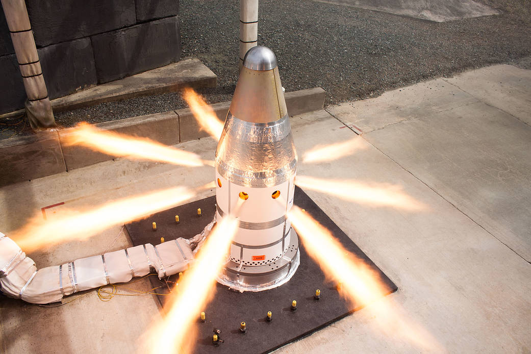
Attitude Control Motor
The attitude control motor steers the Orion crew module to safety and orients it with the heat shield facing the Earth in the case of an emergency. The motor is essential because it helps stabilize Orion and control its trajectory as it moves away from the rocket.
Built by Northrop Grumman and tested at their facility in Elkton, Maryland, the attitude control motor consists of a solid propellant gas generator and eight equally spaced valves capable of providing 7,000 pounds of thrust in any direction. The unique valve control system enables each valve to open and close, directing the flow of gas.
The attitude control motor has undergone three qualification tests. During each of the three 30-second hot-fire tests, the motor’s eight high-pressure valves directed more than 7,000 pounds of thrust in multiple directions, proving the motor can provide enough force to orient Orion and its crew for a safe landing.
| Weight | 1,700 lbs. includes 650 lbs. propellant 7,000 lbs. thrust |
| Fuel Type | Solid Fuel – carboxyl-terminated polybutadiene (CTPB) |
| Burn Duration | About 30 sec. |
The first test, Qualification Motor-1 (QM-1), took place under ambient temperature conditions, or the conditions of the naturally surrounding environment, at approximately 70 degrees Fahrenheit. The test confirmed the system performed as intended under average temperature conditions a motor might experience during a launch.
The second test, Qualification Motor-2 (QM-2), took place under hot conditions at approximately 94 degrees Fahrenheit. The test confirmed the system performed as intended under the maximum temperature conditions this motor might experience during a launch.
The third test, Qualification Motor-3 (QM-3), took place under cold conditions at approximately 30 degrees Fahrenheit. To demonstrate worst case conditions, the motor was ignited using one of two initiators and simulated high altitude vacuum conditions. The test confirmed the system performed as intended under the minimum temperature conditions a motor might experience during a launch.
Attitude Control Motor Testing in Elkton, MD
| QM-1 | March 20, 2019 | Ambient Condition | 70°F |
| QM-2 | Aug. 22, 2019 | Hot Condition | 94°F |
| QM-3 | Feb. 25, 2020 | Cold Condition | 30°F |
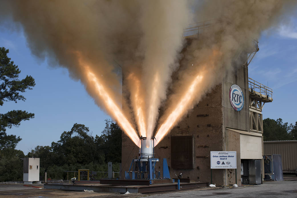
Jettison Motor
In the event of an emergency, the jettison motor ignites to separate Orion’s LAS structure from the spacecraft, which could then deploy its parachutes for a safe landing. During a nominal mission, the jettison motor activates after stage-two ignition to separate the LAS from the spacecraft as the crew members continue their journey. This critical task makes it the only motor on the LAS to fire on every mission. The motor was built by Aerojet Rocketdyne and tested by engineers at the U.S. Army Redstone Test Center on Redstone Arsenal in Huntsville, Alabama.
During each 1.5 second hot-fire test, the jettison motor successfully produced more than 40,000 pounds of thrust in different conditions it might encounter during launch.
Weight
900 lbs.
Includes 360 lbs. propellant
40,000 lbs. thrust
Fuel Type
Solid Fuel – hydroxyl-terminated polybutadiene (HTPB)
Burn Duration
About 1.5 sec.
The first test, called Qualification Motor-1 (QM-1), took place under high temperatures, at 105.9 degrees Fahrenheit. The test confirmed the system performed as intended under the maximum temperature conditions a motor might experience during a launch.
The second test, Qualification Motor-2 (QM-2), took place under cold temperatures, at 23.6 degrees Fahrenheit. The test confirmed the system performed as intended under the minimum temperature conditions a motor might experience during a launch.
The third test, Qualification Motor-3 (QM-3), took place under ambient temperature conditions, or the conditions of the naturally surrounding environment, at 73.1 degrees Fahrenheit. The test confirmed the system performed as intended under average temperature conditions a motor might experience during a launch.
Aerojet Rocketdyne also completed a demonstration test on Aug. 28, 2019 with the first jettison motor that utilized Aerojet Rocketdyne’s Orange, Virginia, facility for propellant mixing and loading and motor final assembly. The Demonstration Motor-4, or DM-4 test, rounded out an extensive two-year transition effort that increased affordability and demonstrated that there was no loss of fidelity or quality in the transfer of the program from California to Virginia.
Jettison Motor testing in Redstone Arsenal, AL
| QM-1 | March 20, 2019 | Ambient Condition | 70°F |
| QM-2 | August 22, 2019 | Hot Condition | 94°F |
| QM-3 | Feb. 25, 2020 | Cold Condition | 34°F |
Parachute Testing
Orion’s parachute system is designed to ensure a safe landing for astronauts returning from deep space missions to Earth in the crew module at speeds exceeding 25,000 mph. While the Earth’s atmosphere acting on Orion’s heat shield will initially slow the spacecraft down to 325 mph, the parachutes are needed to get to a safe landing speed of 20 mph or less, making it a critical system.
The parachute system includes 11 parachutes that begin deploying at just under five miles in altitude. A series of cannon-like mortars fire to deploy three of the four parachute types, pyrotechnic riser cutters, and more than 13 miles of Kevlar lines attaching the top of the spacecraft to 36,000 square feet of parachute canopy material. Within 10 minutes of descent through Earth’s atmosphere, everything must deploy and assemble itself in a precise sequence to slow Orion and its crew for splashdown in the ocean. The parachute system also must be able to keep the crew safe in several failure scenarios, such as mortar failures that prevent a single parachute to deploy, launch vehicle aborts, or other conditions that produce loads close to the maximum material capability. Each of Orion’s main parachutes weigh 270 pounds and is packed to the density of oak wood to fit in the top part of the spacecraft, but once fully inflated, the three mains cover almost an entire football field.
The system underwent 17 developmental and eight qualification tests at the U.S. Army’s Yuma Proving Grounds in Arizona. The Engineering Development Unit (EDU) test series ran from 2011 to 2016 and tested parachute system design data. During the development series, engineers tested different types of failure scenarios and extreme descent conditions to refine the design and ensure Orion’s parachutes will work in a variety of circumstances.
Qualification airdrop and ground testing took place from 2016 to 2018. During the qualification testing, engineers evaluated the performance of the parachute system during normal landing sequences as well as several failure scenarios and a variety of potential aerodynamic conditions to ensure astronauts can return safely from deep space missions.

The Parachute Compartment Drop Test Vehicle (PCDTV), an aerodynamically stable dart-shaped test vehicle, was used to provide high dynamic pressure test conditions. The Parachute Test Vehicle (PTV), a less stable, capsule-shaped test vehicle, was used more often and provided flight-like wake environments during tests.
While airdrop testing was a vital, and very visible, component to the development of Orion’s parachutes, ground testing and analysis were equally important to ensure success. Airdrop testing is expensive, time-consuming, and cannot physically reach all possible spaceflight deployment conditions, but its data helped generate computer models of parachute performance and allowed the team to evaluate the parachutes in altitude and airspeed regimes that were unable to be thoroughly drop tested. Repeated simulation of the parachutes with varied parameters, called the Monte Carlo method, allowed the team to estimate the bounds of what parachute loads and performance should be expected throughout the life of the program.
Ground testing of material capabilities was coupled with the parachute simulations to determine how much structural margin exists in the system. This combination of ground tests, airdrop tests, and analysis qualified the system for Artemis flights with astronauts. Orion’s parachute system consists of:
Three forward bay cover parachutes (FBCP) used in conjunction with pyrotechnic linear thrusters to ensure separation of the forward bay cover (FBC), which protects Orion and its parachutes during the heat of entry into Earth’s atmosphere. The FBCP are packed using a hydraulic press, with forces as high as 3,000 pounds.
Two drogue parachutes used to slow and stabilize the crew module during descent and establish proper conditions for main parachute deployment to follow. The drogues are mortar deployed from the crew module forward bay at 100 feet per second (68 mph) minimum muzzle velocity. The drogues are packed using a hydraulic press, with forces as high as 10,000 pounds.
Three pilot parachutes used to lift and deploy the main parachutes from the crew module forward bay. They are mortar deployed from the crew module forward bay at 112 feet per second (76 mph) minimum muzzle velocity. The pilots are packed using a hydraulic press for convenience but are much lower density and can be “hand packed” if required.
Three main parachutes used to slow the crew module for landing to a speed that ensures astronaut safety. The mains are packed using a hydraulic press, with forces as high as 50,000 pounds. They are autoclaved with a vacuum applied to the parachute at 190 degrees Fahrenheit for 48 hours to help “set” the packing and remove atmospheric moisture.
The parachute system was developed and tested by NASA and the agency’s contractor partners. Parachutes are designed and fabricated by Airborne Systems in Santa Ana, California; the mortars are provided through Lockheed Martin by General Dynamics Ordinance & Tactical Systems, located in Seattle; and project management is performed by Jacobs Engineering’s Engineering Science Contract Group in Houston.
Parachute Quick Facts
Three Forward Bay Cover Parachutes (FBCP)
| Diameter | 7 ft. |
| Length | 100 ft. |
| Weight | 8 lbs. each |
| Material | All Kevlar materials |
| Deployment Altitude | 26,500 ft. |
| Deployment Vehicle Speed | 475 ft. per sec. (324 mph) |
| Density | Approx. 49 lbs. per cubic ft. (roughly the same as oak) |
| Final Packed Size | 7.2” by 6.9” (0.16 cubic ft.) cylinder |
Three Pilot Parachutes
| Diameter | 10 ft. |
| Length | 70 ft. |
| Weight | 9 lbs. each |
| Material | Kevlar and Nylon materials |
| Deployment Altitude | 9,500 ft. |
| Deployment Vehicle Speed | 190 ft. per sec. (130 mph) |
| Density | Approx. 35 lbs. per cubic ft. (roughly the same as pine) |
| Final Packed Size | 6.8” by 13.3” (0.3 cubic ft.) cylinder |
Two Drogue Parachutes
| Diameter | 23 ft. |
| Length | 100 ft. |
| Weight | 60 lbs. each |
| Material | Kevlar and Nylon materials |
| Deployment Altitude | 25,000 ft. |
| Deployment Vehicle Speed | 450 ft. per sec. (307 mph) |
| Density | Approx. 40 lbs. per cubic ft. (roughly the same as oak) |
| Final Packed Size | 16.5” by 16.2” (2 cubic ft.) cylinder |
Three Main Parachutes
| Diameter | 116 ft. |
| Length | 220 ft. |
| Weight | 270 lbs. each |
| Material | Kevlar and Nylon materials |
| Deployment Altitude | 9,000 ft. |
| Deployment Vehicle Speed | 190 ft. per sec. (130 mph) |
| Density | Approx. 44 lbs. per cubic ft. (roughly the same as oak) |
| Final Packed Size | Approx. 7 cubic ft. irregular shape to fit into the vehicle forward bay |
Parachute Engineering Development Drop Testing
| Number | Date | Vehicle | Alt. | FBC | Drogue | Pilot | Main | Primary Test Objective(s) |
| CDT 3-1 | 09/21/11 | PCDTV | 25 kft | – | 2 | 3 | 2 | Nominal system |
| CDT 3-2 | 12/20/11 | PCDTV | 25 kft | – | 2 | 2 | 3 | Drogue skip 2nd, Pilot & Main fail to deploy |
| CDT 3-3 | 02/29/12 | PTV | 25 kft | – | 2 | 3 | 3 | Nominal system with flight-like wake behind PTV |
| CDT 3-4 | 04/17/12 | PCDTV | 25 kft | – | 2 | 3 | 3 | High Q Drogue deploy, Main skip 2nd |
| CDT 3-5 | 07/18/12 | PTV | 25 kft | – | 2 | 3 | 3 | Main skip 1st |
| CDT 3-6 | 08/28/12 | PCDTV | 25 kft | – | 2 | 3 | 3 | Max Q Drogue deploy |
| CDT 3-7 | 12/20/12 | PTV | 25 kft | – | 1 | 3 | 3 | Drogue fail |
| CDT 3-8 | 02/12/13 | PCDTV | 25 kft | 3 | 2 | 3 | 3 | High Q Drogue Deploy, Drogue skip 1st, flagging Main |
| CDT 3-9 | 05/01/13 | PTV | 25 kft | – | 1 | 3 | 3 | Drogue fail, Main skip 1st |
| CDT 3-10 | 07/24/13 | PTV | 35 kft | – | 2 | 3 | 3 | Main skip 1st & released |
| CDT 3-11 | 01/16/14 | PTV | 25 kft | 3 | 2 | 3 | 3 | FBC & nominal system |
| CDT 3-12 | 02/26/14 | PCDTV | 35 kft | 3 | 2 | 2 | 2 | Max Q Drogue deploy, Pilot & Main fail |
| CDT 3-13 | 04/23/14 | PTV | 13 kft | – | – | 3 | 3 | Straight to Mains deploy |
| CDT 3-14 | 06/25/14 | PTV | 35 kft | 3 | 2 | 3 | 3 | FBC & Main skip 2nd |
| CDT 3-15 | 12/18/14 | PTV | 25 kft | – | 2 | 2 | 2 | Textile risers, Main design changes |
| CDT 3-16 | 08/26/15 | PTV | 35 kft | 2 | 1 | 2 | 2 | Minimum System, textile risers, 85% PRL |
| CDT 3-17 | 01/13/16 | PCDTV | 30 kft | 2 | 2 | 3 | 3 | High Q Drogue and Main deploy |
Parachute Qualification Drop Testing
| Number | Date | Vehicle | Alt. | FBC | Drogue | Pilot | Main | Primary Test Objective(s) |
| CQT 4-1 | 09/30/16 | PCDTV | 35 kft | 2 | 2 | 3 | 3 | Two FBCP, nominal system, bounding high Q Drogue and Main deploys |
| CQT 4-2 | 03/8/17 | PTV | 25 kft | – | 2 | 3 | 3 | No FBCPs, min Q Drogue deploy |
| CQT 4-3 | 06/14/17 | PTV | 25 kft | – | – | 3 | 3 | Straight to Mains, low Q deploy |
| CQT 4-4 | 09/13/17 | PTV | 25 kft | – | – | 3 | 3 | Straight to Mains, high Q deploy |
| CQT 4-5 | 12/15/17 | PTV | 35 kft | 2 | 2 | 2 | 2 | Two FBCPs, two Mains |
| CQT 4-6 | 03/16/18 | PTV | 35 kft | 2 | 2 | 3 | 3 | Nominal system with FBC |
| CQT 4-7 | 07/12/18 | PCDTV | 35 kft | 2 | 2 | 2 | 2 | Two Pilots/Mains, high Q Drogue and Main deploy |
| CQT 4-8 | 09/13/18 | PTV | 35 kft | 3 | 2 | 3 | 3 | Nominal system with FBC |
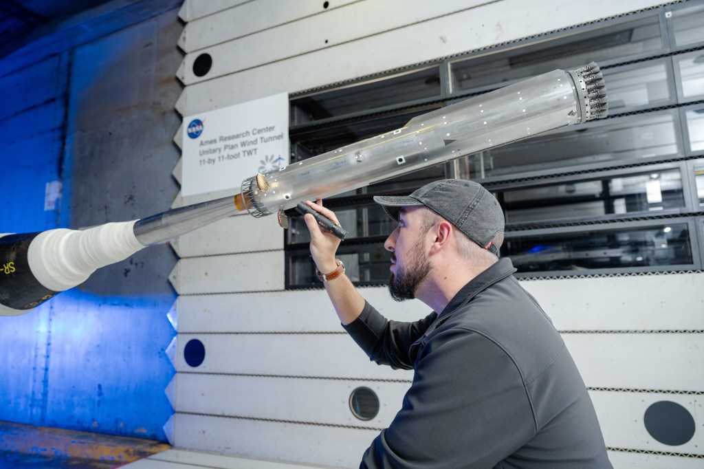
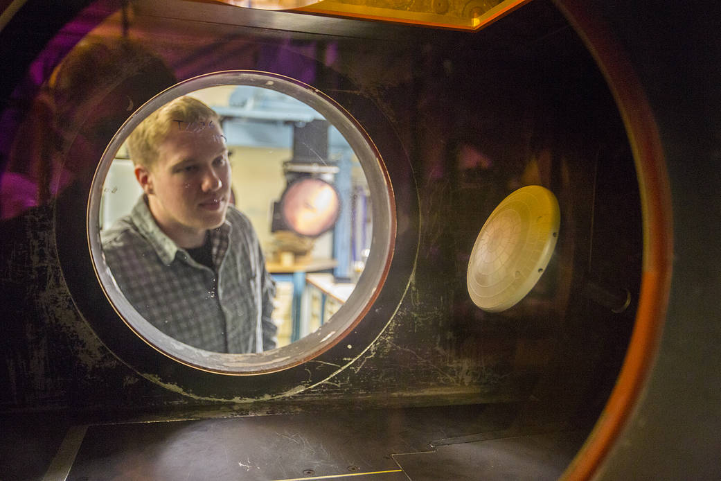
Wind Tunnel Testing
In order to successfully carry out its various missions, Orion’s flight behavior in Earth’s atmosphere must be accurately designed and understood. Wind tunnel testing and simulations have played an important role in developing the aerodynamic, aerothermal, and aeroacoustics databases for atmospheric flight of Orion. The databases help to verify the performance, controllability, thermal protection system, structure, and safety of the vehicle during all phases of atmospheric flight, including launch aborts, by allowing accurate flight simulations and informing good design for the vehicle.
Defining the crew module aerodynamics, both static and dynamic, is important in order to ensure stable and controllable flight from entry into Earth’s atmosphere to parachute deployment and descent. It is also important to define for the launch abort system (LAS) to ensure successful launch aborts during ascent from the launch pad to orbit. Defining the crew module and LAS aerothermal environments is important in order to design thermal protection systems that will protect them from heat during atmospheric entry, ascent, and ascent aborts. Characterizing the aeroacoustics is also important to design and test the vehicle structures for the vibrations and loads they will experience during ascent and entry.
The Orion aerosciences testing team has completed more than 120 tests as part of developing the aerodynamic, aerothermal and aeroacoustic databases for Orion. Tests have been conducted in 25 different wind tunnels, 4 ballistic ranges, 2 shock tunnels, and 3 research laboratories across the U.S. The tests have covered a Mach number range of 0.05 to ~20 (38 mph to about 15,000 mph). Tests have been performed at NASA facilities in Virginia, California and Ohio; Department of Defense facilities in Tennessee, Maryland and Florida; and universities such as the University of Buffalo in New York.
During testing, the conditions experienced by the LAS and the crew module are simulated inside the test facility. For tests of ascent aborts, plumes from the LAS motors are simulated with a simulant gas. Air, helium, and rocket fuel were used during these tests in order to understand the jet interactions of the plumes on the vehicle from aerodynamic, aeroacoustic, and aerothermal perspectives. Tests with the LAS attitude control motor, abort motor, jettison motor, and crew module reaction control systems have all been performed. These data are then analyzed, developed into databases, and aerosciences customers will use those databases to design the flight control systems, thermal protection systems, and structural design of the Orion vehicles.
Wind Tunnel Testing
| Test Number | Type | Date | Facility | Description |
| 50-AS | Ascent Acoustics | 5/17/07 | Boeing Polysonic Wind Tunnel (PSWT) | A preliminary investigation into the aeroacoustic loads generated by the Pad Abort Test (PA-1) LAV configuration and the potential reduction in those loads provided by an alternate Launch Abort System configuration (ALAS-2 mod-1) developed by the ALAS project of the NESC. |
| 58-AA | Ascent Acoustics | 10/8/07 | Arnold Engineering and Development Center (AEDC) 4T | Test to identify LAV configuration to adopt for flight. Downselect between ALAS-11 rev 3, rev 8, and rev 10. Approximately12 flush mounted microphones |
| 57-AS | Ascent Acoustics | 11/1/07 | NASA Glenn Research Center (GRC) 8×6 | LAV Ascent Aeroacoustics comparing PA-1 and ALAS-11 rev. 3 configurations with approximately 100 surface mounted microphones |
| 11-CD | Dynamic Stability | 04/8/06 | US Army Aberdeen Test Range | Proof of concept test to evaluate the Aberdeen Research Laboratory telemetry technique for ballistic range test data acquisition and analysis of CM flight. |
| 8-CD | Dynamic Stability | 05/10/06 | NASA Langley Research Center (LaRC) Transonic Dynamics Tunnel (TDT) | Small-amplitude forced oscillation test of CM w/ some unsteady pressures. |
| 12-CD | Dynamic Stability | 06/19/06 | US Army Aberdeen Test Range | Evaluation of improved sabot designs for CM testing at the Aberdeen Test Range |
| 13-CD | Dynamic Stability | 07/6/06 | US Air Force Eglin Ballistic Range | Transonic and supersonic dynamic aero data for zero L/D CM model |
| 15-CD | Dynamic Stability | 09/2/06 | US Army Aberdeen Test Range | Lifting and non-lifting CM models for dynamic aero database development |
| 14-CD | Dynamic Stability | 10/5/06 | NASA Ames Research Center Hypersonic (ARC) Free-Flight Aerodynamics Facility | Transonic and supersonic dynamic aero data of CM at non-zero L/D |
| 18-CD | Dynamic Stability | 01/1/07 | LaRC TDT | Demonstration of Oscillating Turn Table test technique in the TDT to obtain dynamic stability of the CM at high Reynolds numbers. Comparisons with ballistic range data and previous small amplitude forced oscillation test (8-CD) |
| 48-CD | Dynamic Stability | 03/1/07 | LaRC Vertical Spin Tunnel (VST) | Free-flight test of CM at low Mach number to provide dynamic stability estimates for the Pad Abort flight test. |
| 52-CD | Dynamic Stability | 03/1/07 | ARC Fluid Mechanics Laboratory Test Cell 2 (TC-2) | Test technique development to examine issues related to Free-to-Oscillate testing. Will duplicate the conditions of 48-CD test of the CM. |
| 45-AD | Dynamic Stability | 03/9/07 | LaRC VST | Low-Mach number test of LAV in support of PA-1 Flight Test |
| 29-CD | Dynamic Stability | 06/1/07 | ARC Gun Development Facility | Phase 2 of CM dynamic stability at large angles of attack. |
| 82-AD | Dynamic Stability | 12/21/07 | LaRC VST | Forced Oscillation test of LAV in the Vertical Spin Tunnel |
| 27-AD | Dynamic Stability | 03/21/08 | LaRC TDT | Forced oscillation (subsonic and transonic) test of LAV and CM through as much of the 0-180 deg. range as possible |
| 108-CD | Dynamic Stability | 08/25/09 | Bihrle Research VST | Low-speed dynamic stability test to support Orion decisions on back shell angle changes. |
| 109-CD | Dynamic Stability | 11/15/09 | 09 LaRC VST | Dynamic stability of CM under parachutes. |
| 117-CD | Dynamic Stability | 04/1/10 | LaRC VST | Phase 2 of dynamic stability test of CM under parachute |
| 46-AD | Dynamic Stability | 06/1/10 | US Air Force Eglin Ballistic Range | Ballistic range test of LAV. |
| 55-AS | Plume Acoustics | 09/28/07 | Florida State Jet Noise Laboratory | Series of hot- versus cold-jet acoustic experiments to possibility develop scaling laws to allow the use of cold plume tests for the LAV with AM firing. Phase 1 – 2″ 2,000°F jet versus 2″ cold jet. Phase 2 – Same 2 jets with more measurement locations. Phase 3 – ~1″ D nozzle exit hybrid rocket. Phase 4 – Sounding rocket motor plume noise measurements at NASA Wallops Flight Facility. |
| 51-AS | Plume Acoustics | 10/30/10 | ARC Unitary Plan Wind Tunnel (UPWT) | 6%-scale LAV model test to determine the aeroacoustic loading generated by cold air simulation of the AM plumes. ~200 flush microphones. |
| 80-AS | Plume Acoustics | 09/20/10 | ARC UPWT | Hot Helium simulation of AM plumes for acoustic loads. ~200 flush microphones. |
| 53-AA | Plume Jet Interaction (JI) | 05/21/07 | Texas A&M 7×10 Foot Wind Tunnel | First test of subsonic interactions between the ACM plumes and the LAV. Primarily to validate CFD and to provide some data on coast-phase ACM increments for the PA-1 flight test aero database. |
| 16-AA | Plume JI | 06/22/07 | ARC UPWT | Abort loads on the CM due to AM plume JI and proximity to Service Module |
| 59-AA | Plume JI | 09/14/07 | ARC UPWT | High fidelity ACM JI for both Pad Abort-1 flight test article and production ALAS-11rev3B configuration. |
| 60-AA | Plume JI | 01/30/08 | ARC UPWT | Preliminary separation aerodynamics during abort initiation on PA-1 and ALAS-11 rev3B configurations. Preliminary aeroacoustics for nominal ascent (with SM) and abort (LAV only) with cold air plume simulation. |
| 85-AA | Plume JI | 08/20/08 | GRC Aero-Acoustic Propulsion Laboratory | CFD validation test documenting flowfield associated with single AM nozzle at M < 0.3 using PIV. Nozzle at 0°, 25°, and 40° relative to free stream. With and without simplified LAV model. |
| 61-AA | Plume JI | 12/1/08 | LaRC 14- by 22 Foot Wind Tunnel | Subsonic 6%-scale Jettison Motor Jet Interaction test around alpha = 180°. |
| 24-AA | Plume JI | 06/25/09 | AEDC 16T | Transonic/supersonic test of Jettison Motor Jet Interation for LAS jettison during a launch abort (i.e. heat shield forward). |
| 75-AA | Plume JI | 07/24/09 | ARC UPWT | Subsonic, transonic, and low-supersonic ACM Jet Interaction test. |
| 76-AA | Plume JI | 11/24/10 | LaRC UPWT | Supersonic ACM Jet Interaction test (M 1.6 to 4.6). |
| 25-AA | Plume JI | 02/26/10 | ARC UPWT | Supersonic (M 1.6 to 2.5) Jettison Motor Jet Interaction and Jettison LAS/CM Proximity aerodynamics. |
| 26-AA | Plume JI | 08/09/10 | ARC UPWT | Subsonic, transonic, and supersonic AM and ACM Jet Interactions including separation effects data for the LAV. PSP to document pressure loadings during launch aborts. |
| 3-CA | CM Static Aero | 02/10/06 | LaRC UPWT | Study of BL trip techniques on 3%-scale CM model. |
| 7-CA | CM Static Aero | 03/10/06 | LaRC UPWT | Force and moment measurements & pressure distributions, with apex cover on/off and boundary layer transition/tripping study. |
| 5-CA | CM Static Aero | 03/22/06 | ARC UPWT | Force & moments and pressure data on 7.5%- and 3%-scale models. Provided tunnel-to-tunnel comparisons between LaRC and ARC UPWT. |
| 9-CA | CM Static Aero | 04/20/06 | LaRC Mach 6 Tunnel | 3%-scale CM test for alpha from 0 to 180°. |
| 1-CA | CM Static Aero | 12/08/06 | LaRC UPWT | Boundary layer transition measurements with IR thermography and Temperature Sensitive Paint. |
| 19-AA | LAV Static Aero | 01/29/07 | Boeing PSWT | 3%-scale transonic test of PA-1 LAV configuration for 0-180° angle of attack. |
| 54-AA | LAV Static Aero | 04/13/07 | Lockheed High-Speed Wind Tunnel | Quantify the roll coupling with angle of attack caused by the clocking of the abort motor nozzles on the PA-1 configuration. Study effective-ness of various nozzle fairings in relieving the roll interaction |
| 88-AA | LAV Static Aero | 10/20/10 | LaRC VST | Test of the PA-1 Launch Abort Tower alone to define the postjettison aerodynamics. |
| 83-AA | LAV Static Aero | 06/1/08 | LaRC National Transonic Facility | High-Re effects on unpowered LAV aerodynamics. |
| 122-PA | Static Aero | 11/8/10 | ARC TC-2 | Small-scale test of Forward Bay Cover aerodynamics to validate CFD and engineering models of the FBC jettison event. |