


![Request for Information – Potential [Placeholder for Prize]](https://assets.science.nasa.gov/dynamicimage/assets/science/psd/solar/2023/09/s/solarsystem_0.jpg?w=1024)


Mission Control Center
Since 1965, mission control has been the helm of America’s human spaceflight. NASA’s Christopher C. Kraft Mission Control Center (MCC) at the Johnson Space Center in Houston is the primary facility where flight controllers command and control human spacecraft missions. Since International Space Station assembly began in 1998, the center has become a focal point for human spaceflight worldwide. The teams that work in mission control have been vital to every U.S. human spaceflight since the Gemini IV mission in 1965, including the Apollo missions that took humans to the Moon, the more than 110 space shuttle flights since 1981 and today’s commercial crew flights.
MCC and Artemis I
MCC is comprised of several flight control rooms (FCR), including FCR-1, FCR-2 and the Red, White, and Blue FCRs. Work to transform the White FCR from its shuttle legacy configuration into a modern mission control configuration to support 21st century missions, known as the MCC-21 effort, began in January 2013. The upgraded White FCR is ultimately intended to serve as the mission control for flights of NASA’s Orion spacecraft on missions to deep space destinations.
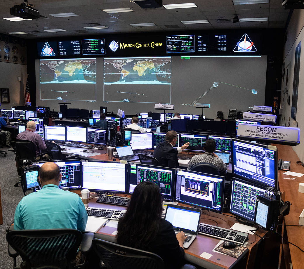
MCC is the facility from which flight operations personnel will remotely monitor and operate the Orion spacecraft and receive data from Orion and the Space Launch System (SLS) during Artemis missions. During Artemis I, as Orion travels toward the Moon over the course of several days, flight controllers will command Orion from the ground six times to correct its trajectory to ensure the spacecraft can fly by the Moon at the correct time and place. This includes trajectory corrections that enter Orion into the planned lunar orbit, exit that orbit, and then return to Earth to splashdown in the Pacific Ocean.
The flight control team has been training for the Artemis I mission since 2019, by constantly refining and practicing procedures they will use on the ground to monitor, command, and control Orion, and continues to do so until several weeks before the mission. This includes performing numerous simulations at MCC of the various parts of Orion’s journey. Flight controllers at MCC train and prepare by simulating Orion’s launch through outbound powered flyby to the Moon, including the trans-lunar injection (TLI) burn that sends the spacecraft out of Earth orbit and toward the Moon. MCC also simulates Orion’s orbit around the Moon and return powered flyby from the Moon through entry, descent, landing, and recovery, including the final trajectory corrections and burns Orion will need to enter the atmosphere and splashdown in the Pacific Ocean.
Simulations and testing have included joint operations between Lockheed Martin and the NASA Flight Operations Directorate, with NASA teams doing real-time monitoring and commanding of the Integrated Test Lab (ITL) Orion vehicle in Denver from the MCC in Houston. The ITL Orion vehicle replicates Orion’s computer, wiring, and avionics systems configurations. Testing has also been done with a low-fidelity Orion at the Exploration Development Lab in Houston as well as with the actual Orion spacecraft.
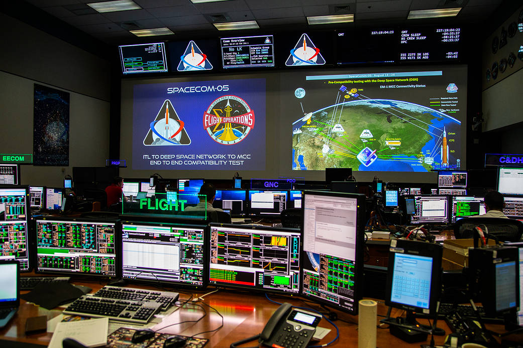
Engineers have also tested the Orion communications system to ensure the spacecraft and MCC can flawlessly communicate and send data through NASA’s satellite networks in space and on the ground. To communicate during Artemis I, MCC and Orion will use NASA’s Near Space Network, Tracking and Data Relay Satellite (TDRS) services, and Deep Space Network. The Near Space Network consists of Direct-to-Earth services, which use a worldwide network of ground stations to provide communications and navigation services during launch, as well as navigation services at various points on Artemis I. Tracking and Data Relay Satellite (TDRS) services provide near-continuous communications services to spacecraft near Earth, and play a critical role during launch and low-Earth orbit phases of Artemis I as well as during entry into Earth’s atmosphere, splashdown, and recovery. The Deep Space Network will handle Artemis I communications beyond Near Space Network coverage, en route to and in orbit around the Moon.
MCC has verified these communication systems work with Orion during tests of different Artemis I scenarios, including pre-launch countdown through the point at which Orion data is relayed through the DSN, operations in lunar orbit, handover between the DSN and the Near Space Network during Orion’s trajectory from the Moon back toward Earth, and post-splashdown operations. Previous testing also verified communications through the Near Space Network satellites and ground station at Cape Canaveral, and also included support from personnel at the Huntsville Operations Support Center, also known as the HOSC, at NASA’s Marshall Space Flight Center, to verify they can receive data from the SLS rocket. Engineers at the SLS Engineering Support Center at Marshall also conducted voice tests to ensure teams across the country, including flight controllers in Houston, launch controllers in Florida, and engineering teams at several locations including in Huntsville can communicate by voice.
Rapid Prototyping Lab
The focus of NASA’s Rapid Prototyping Laboratory (RPL) located at the Johnson Space Center in Houston is to define and develop the whole suite of over 60 display formats and interactive controls for the Orion spacecraft.
The RPL team provides quick, creative, and efficient solutions to an array of issues that engineers and astronauts may face during missions. The team has used this approach to streamline the more than 2,000 switches used on the space shuttle into a new interface for the Orion cockpit, using just three display units, about 60 physical switches, two rotational hand controllers, two translational hand controllers, and two cursor control devices.
This new interface not only eliminates mass from Orion, but the software also makes it easier to operate the capsule by automatically generating dialogue boxes to help processes move along more efficiently. Astronauts on the space shuttle relied on nearly 200 pounds of operating manuals to help them fly the orbiter. On Orion, electronic procedures are programmed into the system to aid the crew in daily and emergency processes, making these large manuals of system operations obsolete and saving the crew time and space.
The RPL team prototypes these display formats as part of an integrated cockpit simulation hosted on various Orion cockpit mockups around the Johnson Space Center. The mockup is being used to provide a realistic environment for astronauts to evaluate the Orion cockpit and to practice Orion spacecraft operations. It is used to implement test scenarios to help decide on final design issues such as the types of controls during the different phases of flight, organization of the display formats and navigation, hardware selection and ergonomics, operational concepts, and display format specification and prototyping.
The Orion cockpit mockup includes three display units, hand controllers and cursor control devices for two operators, and seven switch panels set up in an “on your back” fashion to simulate ascent and entry into Earth’s atmosphere. All the controls in the mockup are functional and connected to a simulation of the Orion spacecraft display suite. A half shell, recovered from another project, provides a representation of being inside a capsule. Additionally, an out-the-window video taken during EFT-1 is projected onto a screen outside the mockup shell, giving users an idea of what the view would be like on the way to and from space. Audio files from the flight test are synchronized with the video and played through a surround sound system, to further immerse the users.
Systems Engineering Simulator/Reconfigurable Operational Cockpit
The Systems Engineering Simulator (SES) at NASA’s Johnson Space Center is a real-time, crew-in-the-loop engineering simulator for the space station, Orion, and advanced programs. The SES provides the ability to test changes to existing space vehicles and flight software, test the interaction of a new vehicle system with existing systems, create models of new vehicles (that may or may not exist yet) for engineering analysis, and evaluate display and control concepts and modifications.
For Orion, the SES provides simulation of the vehicle with accurate six-degree-of-freedom equations of motion, the Orion guidance, navigation, and control system, and sensor and effectors; and allows for Orion engineering studies such as proof of concept, operational feasibility, and design assessment. The SES also provides mission support and evaluation through procedure development, training, and flight support.
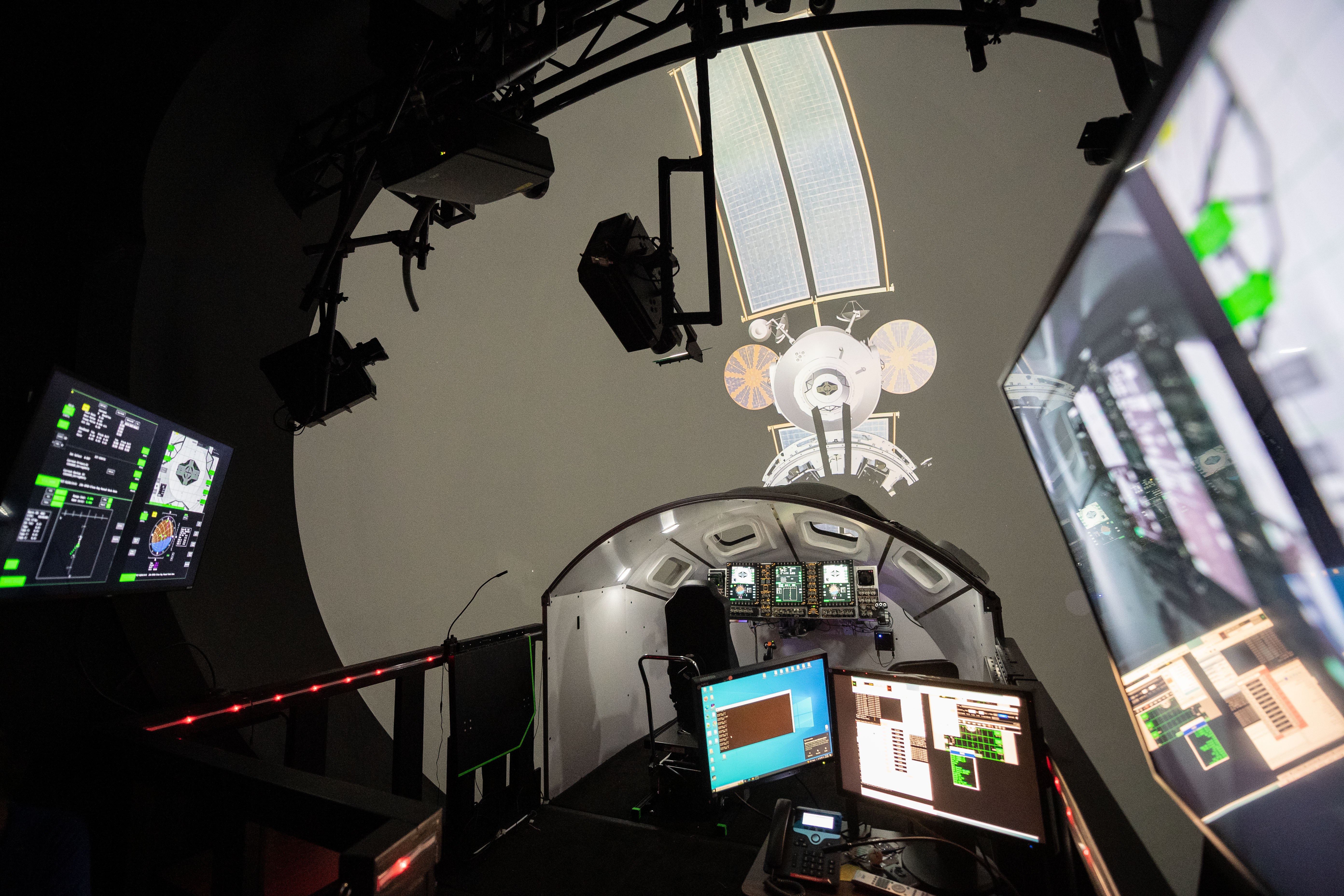
The Reconfigurable Operational Cockpit (ROC) is a reconfigurable cockpit mockup located within the SES Beta Dome, a 24-foot-diameter hemispherical dome upon which one continuous image is projected. This allows crewmembers and engineers to perform tests, evaluations, or training in a controlled cockpit environment while viewing a modeled external environment through the cockpit windows. Orion cockpit simulations have been performed with the ROC, which can simulate both seated and reclined Orion cockpit positions and can use the dome visual system to simulate out-the-window viewing.
Orion Mission Simulator
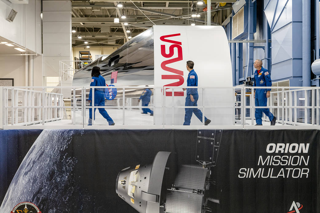
The Orion Mission Simulator (OMS) is a full-task mission trainer at NASA’s Johnson Space Center used to train crew and flight control teams on Artemis missions. The high-fidelity vehicle simulations, which incorporate real flight software, along with extensive malfunction capabilities, provide these teams training on nominal flight activities as well as complex malfunction scenarios, including emergency events.
The OMS is comprised of several components: Orion and SLS Program-provided software simulations and supporting files, Flight Operations Directorate (FOD) training systems infrastructure, user support tools, network simulations, and crew station hardware.
The SOCRRATES-lite (Software Only CEV Risk Reduction Analysis and Test Engineering Simulator) and the ARTEMIS (Ares Real-Time Environment for Modeling, Integration, and Simulation) are used to model both Orion and SLS, respectively. Both are deployed in the FOD training systems infrastructure, which includes computational hardware and data network equipment. The infrastructure also provides a communications and tracking network simulation) of various space to ground networks and allows the vehicle simulations to communicate with the Mission Control Center (MCC) in a very flight-like manner.
The flight crew uses the crew station to interface with the vehicle simulations and with the MCC. The forward cabin of the crew station is accurate in scale to the flight vehicle for the pilot and commander, as well as all four windows with high fidelity simulated out-the-window scenes. A full-scale docking tunnel is also included and will be outfitted with a low fidelity hatch for rendezvous and proximity operation tasks. The crew station is outfitted with high-fidelity displays and controls and high-fidelity crew seats. A breathing air system is also included that will utilize high-fidelity Apollo fittings to supply air to crew, as well as a chilled water suit cooling system to support two suited crew members.
The OMS will offer the crew both visual and aural cues to reinforce data seen on the display units. Sound bites from recorded missions will be tied to parameters in the simulation: when a trigger is set, the appropriate sound bite will annunciate. Simulated window views will also be generated based on simulation parameters. These cues are important in providing the crew situational awareness.
For Artemis I, the SOCRRATES and ARTEMIS simulations are run independently, and the crew station is not used. For Artemis II, SOCRRATES and ARTEMIS will be integrated to run as a single stack simulation and will be integrated with the crew station. The simulations will be modified as required to support future missions.
Platform
288” Platform + 132” Stairs = 420” L x 318” D x 167” H
Crew Station
190.94” W x 184” L x 125.95” H, fixed-base, oriented horizontally with the seats looking forward.
Total Volume Inside Crew Station
1005 cubic feet
Overall Artemis II Crew Station Dimensions Including Platform
420” L x 318” D x 242.57” H
Space Vehicle Mockup Facility
The Space Vehicle Mockup Facility (SVMF) at Johnson Space Center provides spatially accurate flight vehicle mock-ups for engineering development, world class training for space flight crews and their support personnel, as well as high-fidelity hardware for real-time mission support. A major task of the SVMF is to support engineering and mission operations evaluations for the Orion Program. All mockups and part-task trainers are available to support troubleshooting on the ground any time problems develop on orbit in real time.
The SVMF houses a medium-fidelity mockup of the Orion capsule for support of future exploration. The items inside the mock-up of the Orion cabin are accurately placed within one inch of their location in the real flight vehicle. The mockup is currently used for development of components in the Orion cabin, assessments of interior layouts, and human-in-the-loop development and verification testing.
A variety of training is conducted in the SVMF mockup to prepare for emergency operations, on-orbit maintenance, photo/TV, stowage and handling, EVA/airlock operations, and scientific payload operations. The mockup is also used for a variety of engineering and operations evaluations such as on-board stowage evaluations, fit checks, and procedures development and verification.
Human-In-The Loop Evaluations
Human-in-the-loop evaluations, or HITL, are done at Johnson Space Center to make sure Orion’s displays and controls are operable for all mission tasks and the living space is properly designed for astronauts of all sizes. HITL testing involves humans simulating and evaluating the tasks and interactions performed in the crew module, extending the design process beyond 2D modeling. The wide variety of testing in different Orion mockups reveals design and integration problems, and opportunities for cost efficient improvements.
Display & Controls
Orion crew module display formats (i.e. software user interfaces) are frequently evaluated in HITL testing to ensure successful crew interaction for the breadth of tasks required. HITLs have informed the design and operation of the Orion displays and controls, including the hand controllers, switch interface panels, display format legibility (including during vibration), off-angle viewing, and design aspects such as switch guards, spacing, and strength to operate. This testing is performed in the most flight-like facilities possible in order to ascertain whether the crew will be able to safely pilot and control the vehicle given the expected avionics latency and system response, and for any anticipated contingency situations.
Seat Design
The design of seating in the crew module is tested to ensure that the seats can work for anyone from the 1st to 99th percentile of body anthropometries – from a 4-foot-10-inch, 94-pound female to a 6-foot-5-inch, 243-pound male. This includes testing the adjustable seat pans, foot plate, and arm rests of the seats and adjusting hand controller mounts to make sure that the smallest or largest of astronauts can reach all the controls.
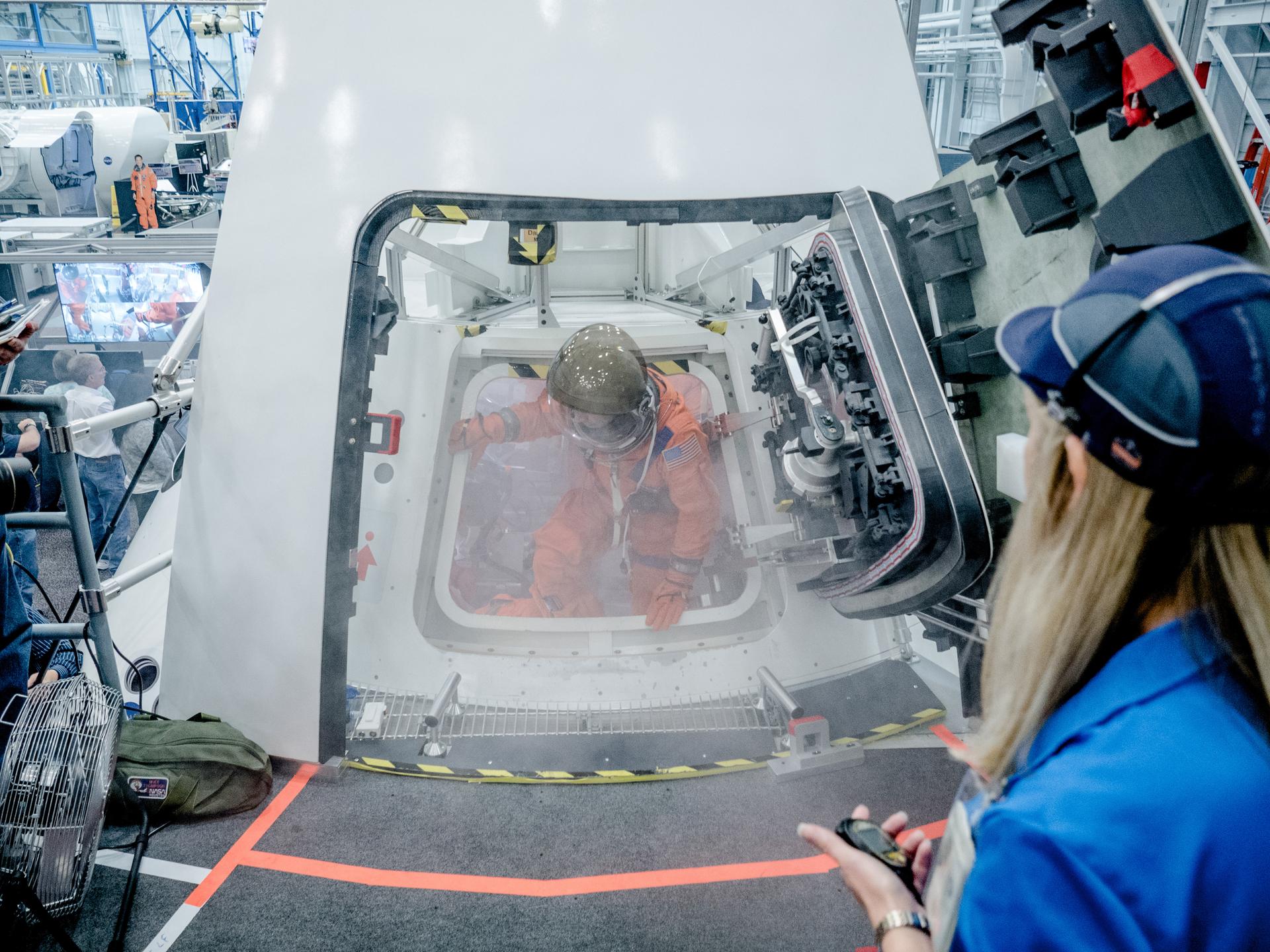
Crew Vehicle Egress & Survival Operations
Testing takes place to make sure the crew can safely and efficiently egress the capsule and includes modifying hardware placement and operability. Timed emergency egress operations are also simulated to determine if time requirements are met using the emergency side hatch (or tandem hatch) opening for pre-launch or post-landing egress. Egress testing evaluates the crew’s ability to exit the spacecraft from both the side hatch and docking hatch, and includes many factors such as the ability to translate through the ocean to safely ingress a life raft in the event of an emergency on Orion.
Habitability & Environmental Systems
HITL testing is performed on crew systems such as the potable water dispenser and food warmer to ensure that the spacecraft is functional as a place to live as well as work. Testing includes the crew’s ability to command changes to the atmosphere to maintain a safe and comfortable shirtsleeve environment, as well as the crew’s ability to respond to emergencies such as a loss of cabin atmosphere or the response to a fire. There are many design controls to prevent these emergencies from occurring in the first place.
Net Habitable Volume
This HITL testing involves making sure there is adequate room for mission tasks and configurations inside the crew module. This includes testing configurations of the cabin for different mission phases, radiation shelter and sleeping bags, as well as testing exercise feasibility, suit donning and doffing, hygiene operations, and medical response. Net habitable volume is a key consideration in Orion cabin design given volumetric constraints with four crewmembers living and working in that volume throughout the mission.
Rendezvous, Proximity Operations, and Docking (RPOD) Operations
This testing evaluates tasks that will be performed in the Orion docking tunnel and vestibule area. This includes docking preparations, docked operations such as arrival and departure, and evaluating ease of operation of docking hardware. Subjects also simulate the steps that would be involved during the preparation and execution of rendezvous, proximity operations, and docking (RPOD) such as performing vestibule leak checks and removing and stowing the docking hatch in a protective cover. RPOD HITL testing also includes handling evaluations of ability to pilot Orion through RPOD fly-around and docking maneuvers. HITL testing also assesses contingency situations, such as the ability to conduct emergency hatch closure operations in the event of a micro-meteoroid/orbital debris strike, resulting in a cabin atmosphere depressurization.
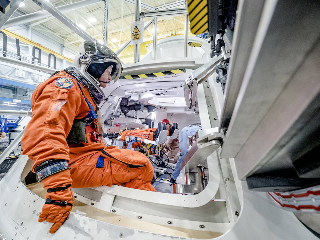
Suited Operations
HITL evaluations take place to test astronauts’ interactions with crew module interfaces while wearing the pressurized Orion Crew Survival System (OCSS) suit. Subjects don the OCSS suit and the suit is brought to pressure to perform various tasks and interactions with hardware. Suited operation HITLs are performed in either a flight-like environment, such as the Orion medium-fidelity mockup in the Space Vehicle Mockup Facility at NASA’s Johnson Space Center in Houston, or in a pressurized glovebox facility for tasks where only pressurized glove interaction needs to be evaluated.
Speech Intelligibility
This series of HITLs evaluates the crew’s ability to communicate with each other and with the Mission Control Center on the ground in various configurations that may be experienced during the mission. The HITL simulates the appropriate noise environment and sound attenuation and then rates the subject’s ability to discern words and sounds. Speech intelligibility testing is critical to ensure that crew can communicate effectively during critical operations, including launch, entry, and in responding to emergencies.
Handling Qualities
This series of HITLs evaluates a pilot’s ability to fly the spacecraft. Testing is done to evaluate how the vehicle responds to hand controller deflections during manual piloting, and to understand whether the total system (including displays and operator aids) allows the pilot to maintain control. Handling qualities HITLs are a critical aspect of human rating of the spacecraft, and they must be conducted in a very flight-like mockup with accurate displays, controls, and software in order to yield valid results.
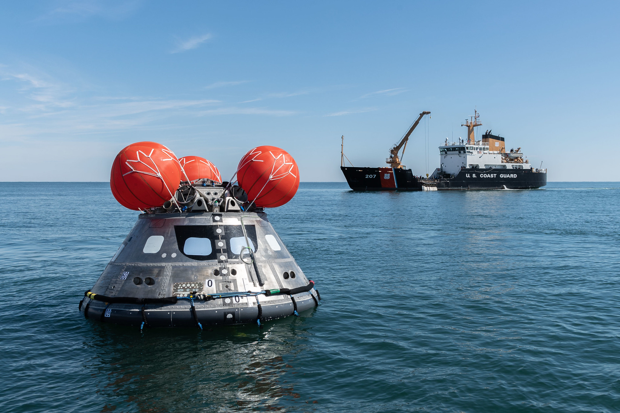
Crew Module Uprighting System
When Orion splashes down in the ocean, it can settle in one of three positions: up, down or on its side. The crew module uprighting system (CMUS) deploys a series of five, bright orange airbags on the top of the capsule to flip Orion right side up in the event it lands and turns upside down.
The system will keep Orion upright and stable after splashdown in the ocean and for at least 24 hours in the waves, if necessary. It takes less than four minutes for the CMUS to upright the capsule. The capsule must be upright for crew module communication systems to operate correctly, and to help protect the health of the astronauts inside who are returning home from future deep space missions. Astronauts can suffer health impacts from extended time hanging upside down in their seat harnesses. Engineers have implemented a series of improvements on the CMUS since Orion’s Exploration Flight Test-1 in 2014. During the flight test, three of the system’s five bags did not properly inflate. The spacecraft landed and remained upright in the water, however had the capsule landed upside down, the two functioning CMUS bags would likely not have been able to fully upright the capsule. Design improvements that have been made since the test include thickening the inner bladder of each round airbag to make it more durable, changing how the bags are packed, developing a hard enclosure for the packed bags, and improving manufacturing processes for better control and consistency.
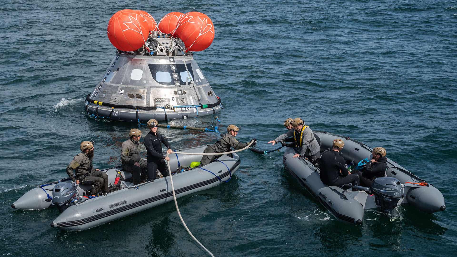
The five bags that make up the CMUS are packed in hard containers and stored atop the capsule inside the structural gussets between the parachutes and other equipment. The areas around the CMUS airbags have been evaluated carefully for protrusions and sharp edges that could potentially puncture the bladder or snag the bags or tethers that keep the bags attached to the spacecraft. Changes to spacecraft components have been made to minimize the sharp edges and snag hazards, and full-scale testing has demonstrated the CMUS can work well alongside the other spacecraft equipment.
The five CMUS bags are inflated with helium gas that is stored in pressure vessels on the spacecraft throughout the mission. Each bag has an independent inflation system. After landing, the CMUS system is initiated and a valve is opened to allow helium to flow into the uprighting bags. As the gas fills the bags, they deploy from their containers and inflate to their full volume. The CMUS will deploy regardless of the landing position of the capsule.
Several full-scale uprighting tests have been performed with a mock-up of the Orion crew capsule. These tests demonstrated that the CMUS would still be able to perform as intended if any one of the five uprighting bags were to fail. This included seven tests in the calm water of the Neutral Buoyancy Lab (NBL), a giant pool at NASA’s Johnson Space Center in Houston primarily used for astronaut training. The Johnson CMUS and NBL teams also successfully completed two tests off the coast of Galveston, Texas, in cooperation with the U.S. Coast Guard Cutter CYPRESS, Air Force personnel, and Texas A&M Galveston. An additional four tests were performed in the Atlantic Ocean, off the coast of Atlantic Beach, North Carolina, in cooperation with the U.S. Coast Guard Station Fort Macon and the USCG Cutter MAPLE. These tests demonstrated performance in a natural wave environment and were instrumental in the certification of the CMUS. The nominal landing location for the Orion spacecraft is approximately 50 miles off the coast of San Diego.
Neutral Buoyancy Lab CMUS Testing
| Date | Test Configuration |
| 6/23/2017 | 5 bags |
| 2/6/2018 | 4 bags (180° out) |
| 2/8/2018 | 4 bags (240° out) |
| 2/14/2018 | 4 bags (300° out) |
| 2/16/2018 | 4 bags (120° out) |
| 6/25/2018 | 4 bags (240° out) – FRB retest |
| 7/10/2018 | 4 bags (240° out) – FRB retest |
At-Sea CMUS Testing
| Date | Test Configuration | Location |
| 12/1/2018 | 4 bags (120° out) | Galveston, TX |
| 12/3/2018 | 4 bags (240° out) | Galveston, TX |
| 3/7/2019 Q* | 4 bags (240° out) | Atlantic Beach, NC |
| 3/10/2019 | 4 bags (120° out) | Atlantic Beach, NC |
| 3/12/2019 Q* | 4 bags (60° out) | Atlantic Beach, NC |
| 3/15/2019 | 4 bags (180° out) | Atlantic Beach, NC |