


![Request for Information – Potential [Placeholder for Prize]](https://assets.science.nasa.gov/dynamicimage/assets/science/psd/solar/2023/09/s/solarsystem_0.jpg?w=1024)


Ames Contributions to Orion
Ames is contributing to this exciting mission in a variety of ways.
TODAY
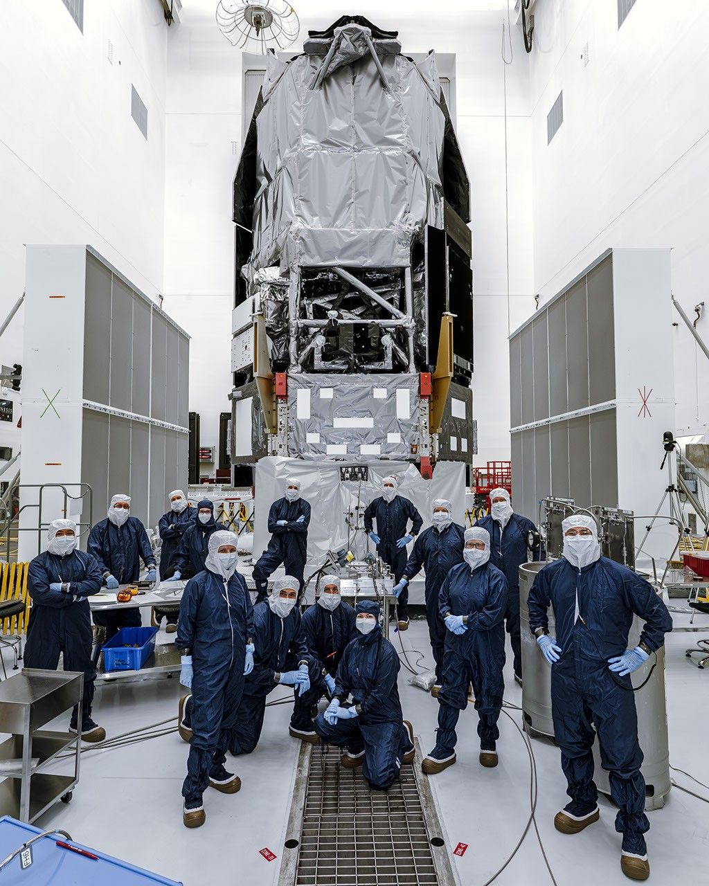
About Orion
NASA’s Orion spacecraft is built to take humans farther than they’ve ever gone before. Orion will serve as the exploration vehicle that will carry the crew to space, provide emergency abort capability, sustain the crew during the space travel, and provide safe re-entry from deep space return velocities. Ames is contributing to this exciting mission in a variety of ways.
Orion’s Exploration Test Flight-1:
Orion will lift off aboard a Delta IV Heavy rocket to perform the first flight test in space of the spacecraft that is being designed to carry astronauts on exploration missions into deep space. Orion will fly this mission without astronauts and will orbit the Earth twice reaching about 3,600 miles above the planet, 15 times higher than the International Space Station.
The spacecraft will re-enter Earth’s atmosphere at close to 20,000 mph and the heat shield will be tested against plasma that is 4,000 degrees F. Orion is to splashdown in the Pacific Ocean off the coast of Baja California where it will be recovered by NASA and U.S. Navy teams.
Ames Contributions Summary
Ames Contributions Details
Entry, Decent and Landing
Thermal Protection Systems (TPS) and Materials:
Starting with the Thermal Protection Systems (TPS) Advance Development Project, engineers at Ames began to develop and test TPS materials for the large disc-shaped heat shield of the Orion space vehicle and the aft cone-shaped section, called the back shell. The TPS protects the vehicle structure and future crews inside the spacecraft from the extremely high temperatures experienced during re-entry into the atmosphere from space.
While the back shell TPS selected for Orion is similar to the insulative tile system used on the space shuttle, the TPS materials on the heat shield need to withstand much higher heating levels and temperatures than the shuttle tile systems. The heating will be higher because Orion will be returning at faster speeds than the space shuttle ever experienced as it travels beyond low Earth orbit, resulting in faster and hotter re-entries.
The TPS material that was selected for the heat shield is called Avcoat, and is similar to the material used in the Apollo heat shields. The material provides some insulation and consumes heat energy by chemical decomposition and gas release.
For the first test flight of Orion, the Avcoat surface will reach temperatures of more than 3,000 degrees Fahrenheit. Instrumentation in the Avcoat and back shell tiles will measure the rise of the surface and internal temperatures during re-entry as well as heating levels and pressures. Additional instrumentation in the Avcoat will record how the surface recedes as it consumes heat energy.
Arc Jet Testing:
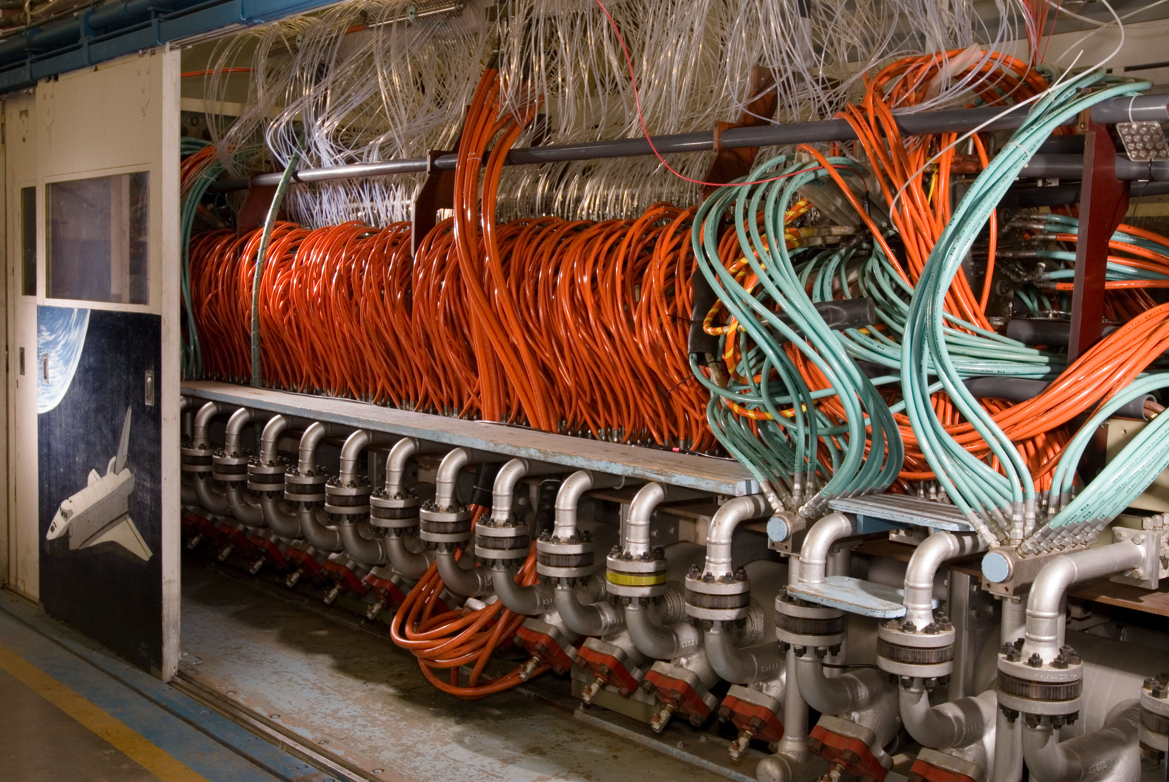
As new TPS materials were developed, they were tested at Ames’ Arc Jet Complex under various heating and pressure environments selected to simulate flight conditions. Engineers took the data measurements recorded, including temperature and rates at which the material receded, to inform and improve the TPS material models. Hundreds of articles have been tested since 2006.
Most TPS testing conducted up to present has relied on arc jet facilities to evaluate the material performance with convective heating, and separate test facilities to evaluate the material performance with radiative heating. The heater in a car is an example of a convective heat source. Radiative heating is what can be felt on the skin when it is exposed to direct sunlight. Since the Orion heat shield will experience both convective and radiative heating during the atmospheric entry, engineers need to be able to test both at the same time. A new arc jet facility upgrade under development at Ames will make this combined heating capability available in 2016.
The radiative heat source being added to the existing arc jet facility uses fiber-laser technology primarily used for heavy metal cutting and welding. NASA is adapting 200 kilowatts of these fiber lasers, referred to as “lightning bolts in a tube,” to produce a roughly 6”x6” radiative “spot” on wedge-shaped samples. This is about 70 million times the radiation that enters your eye when looking at the sun. A set of optical lenses and mirrors expands the laser beam outside the test chamber and shines it through one of the side windows.This exposes a TPS sample to conditions more similar to what the Orion heat shield will have, giving engineers better comparisons between simulations and computer models.
The existing arc jet facilities provide seven different type of convective test configurations, in which gases are heated and expanded to very high temperatures and supersonic and hypersonic speeds by a continuous electrical arc between two electrodes. The gasses pass through a nozzle aimed at a test sample in vacuum and flow over it, producing the desired surface temperature and pressure. The arc jet data are critical for validating thermal material modeling, heat shield designs and repairs, and ultimately for flight qualification.
Sensor Development and Testing:
To capture performance data and metrics on how well thermal paint and tape affect the heat shield during Orion’s first test flight, a group of 34 sensors plugs are inside the heat shield, each with its own instrumentation. The sensors will capture the near-surface and internal temperatures of the heat shield as it re-enters the atmosphere so that engineers will have a complete data profile of its performance to evaluate any improvements that can be made for futures tests.
Heat Shield Development Flight Instrumentation (DFI):
Developmental Flight Instrumentation (DFI) has been a part of human spacecraft vehicles since the days of the Mercury, Gemini and Apollo missions at NASA. When testing a new human vehicle, such as Orion, it is critical to balance the instrumentation to meet engineering Flight Test Objectives. The Flight Test Objectives are designed to best answer and minimize design uncertainties. The DFI architecture is fully developed and lasts through the life of the mission.
In the case of the heat shield, prior to any computer simulation, physical test or validation of the heat shield, engineers needed to design, construct, deliver and certify everything that will measure heat shield response. DFI helps to measure high-level specifications that define general functions for requirements of each component in the heat shield.
In developing the heat shield infrastructure and design, Ames engineers looked to the Mars Science Laboratory Entry, Decent and Landing Instrumentation (MEDLI) as this was a highly successful model to replicate. Replicating many aspects of the MEDLI system meant costs were kept down, delivery time was short and flexibility was increased, even during re-designs of the Orion spacecraft.
The work done for the Orion DFI system demonstrates the broad capabilities of Ames to support multiple mission types including human spaceflight, planetary probes and International Space Station research and development.
Data Parallel Line Relaxation (DPLR):
The geometry of the Launch Abort System is extremely complex and requires an advanced understanding of various gases the space vehicle encounters during planetary re-entry. As specific systems are engaged like the Reaction Control System and the Abort Jettison and Altitude Control Motors, plumes of gas are emitted flowing over the bumps, nooks and crannies of the space vehicle. One of the key methods used by engineers to predict this performance is called DPLR. The software tool solves complex gas airflow equations during all phases of flight, including nominal launch, aborted launch, stage separation, re-entry speeds ranging from hypersonic to subsonic, and parachute deployment.
To reduce risk and cross-check the data derived from DPLR tests, it is validated through similar software analyses at NASA’s Langley Research Center as well as comparisons to measurements made in Arc Jet tests performed at Ames.
Human Performance Testing
Advanced Caution and Warning Systems (ACAWS):
Future human spaceflight mission operations will be quite different than they were in the days of the Apollo or space shuttle programs. The Orion spacecraft will transport humans to remote destinations far beyond the Earth-moon system, where mission operations will have to cope with significant time delays on telemetry and crew-ground communications. Prior to Orion, astronauts relied on flight controllers within the Mission Control Center to troubleshoot real-time anomalies and systems failures. The controllers provided guidance and procedures to astronauts so they could mitigate problems and restore critical system functionality as needed.
On future missions, time delays will be too great for the ground to process and analyze the data, and for crew to receive a response from ground in time to deal with an impending issue. To reduce reliance on the ground, Ames applied artificial intelligence and human factors engineers are developing an Advanced Caution and Warning System (ACAWS), an intelligent system that provides information about software and hardware systems to astronauts and ground flight controllers. ACAWS automatically analyzes information coming from hundreds of onboard sensors to determine what has failed, the consequences of the failure and what actions should be taken to restore critical system functionality.
Human performance engineers recently completed a user evaluation of ACAWS by creating Orion failure scenarios during simulated segments of the Exploration Flight Test-1 (EFT-1), comparing real-time fault management performance by flight controllers who either had access to existing displays of Orion sensor data and existing engineering products, or to these existing tools and to ACAWS. Through these experiments, engineers assess how quickly flight controllers can identify, analyze and respond to failures with and without ACAWS.
In addition to ACAWS, Ames human factors engineers completed a research and development effort to explore and mitigate the effects of full-body vibration on astronauts’ ability to read and understand the information presented on their cockpit displays. Early work on this project occurred in the Human Vibration Laboratory. The Human Vibration Laboratory assesses whole-body vibration impacts on visual, cognitive, and manual performance, while understanding the mechanisms contributing to the vibration-induced deficits, and develops countermeasures to mitigate these deficits. This research yielded data on the on the detrimental effects of the kind of vibration that crew members might feel in Orion while it was being launched on top of an Ares I rocket. By measuring the response time of astronauts when performing tasks that required them to process letters and numbers while experiencing varying levels of whole-body vibration, the engineers discovered at the smallest font size and highest vibration, there was a 50% increase in crew member response time and a six-fold increase in errors.
This study (PDF) paved the way for a whole new set of guidelines and thresholds that spacecraft vibrations can withstand before crew performance suffers operationally significant degradation.
In addition, follow-up studies in the project identified a straightforward way to mitigate vibration effects by “strobing” the display so that it was perceived as being stabilized to the eye. Appropriated calibrated display strobing could be applied anywhere an occupant must read a display under vibration, including aircraft cockpits and construction and farming vehicles.
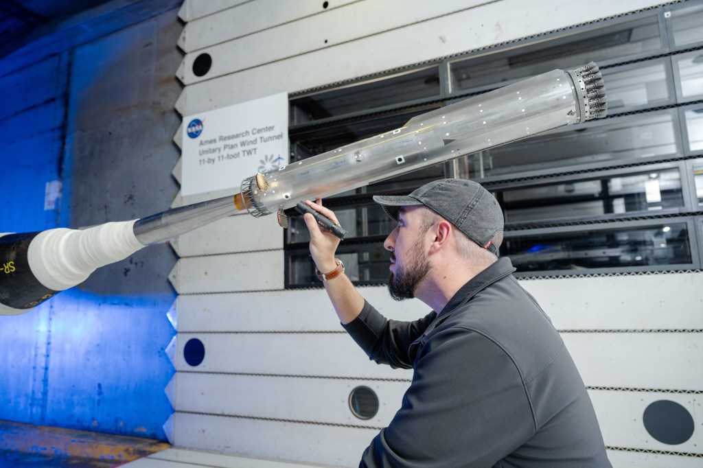
Wind Tunnel Testing
Crew Module Aerodynamics:
Early on during development of the crew module, tests were conducted at Mach 2.5 and 3.0 to test and validate aerodynamics of the vehicle, including the oscillation of the module to ensure it doesn’t tumble through space and atmosphere. The heat shield must be correctly orientated to protect the crew and spacecraft from the atmospheric heat upon planetary re-entry.
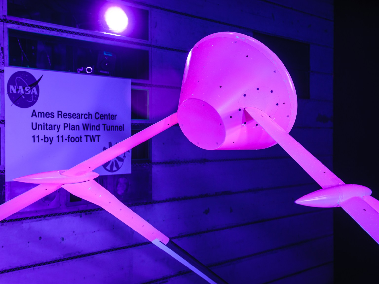
Launch Abort System:
This is a complex, geometric design that required wind tunnel testing to better understand and validate the launch system’s behavior, including test of the abort and attitude control motors, the aeroacoustics from rocket plumes, and the aerodynamics of the vehicle during a variety of launch conditions.
One of the tests was designed to find ways of minimizing the how loud the acoustics of the launch system would be during an actual flight. To do this, engineers added over 200 microphones to a model and using high-pressure air, captured the sounds during ascent and LAS abort. Engineers had to devise a way to test high-pressure gas and heat in order to simulate the acoustic rocket plumes, which hadn’t been done before inside a wind tunnel. The simulation used 75 pounds per second of super heated helium at 700 degrees, which equates to 2.5 semi-trailers of helium every day for 2 weeks.
During these preliminary tests, engineers realized the initial design created unacceptable acoustic levels at 170-plus decibels, between the point that the human throat vibrates so hard swallowing becomes difficult and death of hearing tissue. For comparison, the human ear experiences 30 decibels at a whisper quiet library, 85 decibels inside a car during city traffic, 107 decibels using a power mower at 3 feet away, 115 decibels at a loud rock concert, and 140 decibels near a jet engine gun blast at 100 fee away.
With this information, the shape was changed to an ogive, but further tests indicated sounds were still not acceptable. Two other shapes were 3-D printed, one of which is shaped like a fillet and decreased sounds to acceptable levels.
Supercomputing for Aerodynamics and Aerothermodynamics
Aerodynamic Computational Fluid Dynamics:
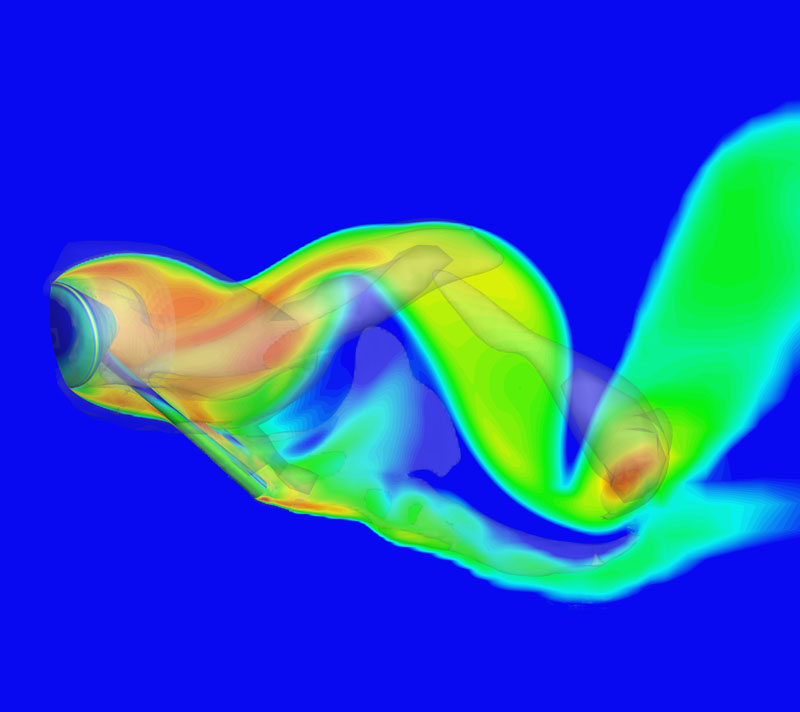
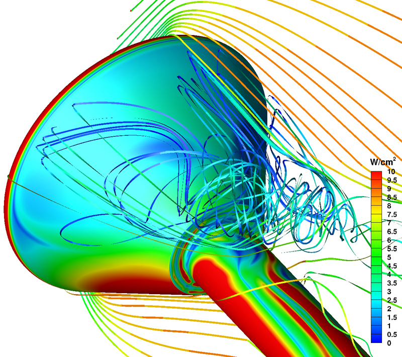
A number of tools first established during the Space Shuttle program at Ames were further developed and used on Orion. With increased computing capability, efficient scripting processes, industry advancements, and years of experience, engineers developed robust and higher fidelity modeling techniques to simulate the aerodynamics and aerothermodynamics of the newly designed Orion spacecraft.
Simulations are used to help determine which types of vehicle designs are viable at maintaining control at all flight stages, times, and speeds. Interactions between the vehicle’s motor plumes, turbulence, and heat transfer require complex computational analyses and experimental tests. The culminated data is used to build high-level aerodynamic models and databases, which are then used to assess comprehensive vehicle performance and support the development of guidance and control systems.
One of the challenges in designing a spacecraft is to properly characterize the aerothermal environment as the vehicle enters a planetary atmosphere. It is critical that designers have an accurate estimate of the peak heating on the vehicle’s surface so they can select thermal protection system (TPS) materials capable of withstanding the extreme temperatures of a high-speed entry. In addition, designers also need a reliable estimate of the total heat load in order to size the TPS thickness.
Since it is not possible to reproduce the exact flight conditions with ground-based experiments, engineers rely heavily on CFD simulations to examine worst-case scenarios and to extrapolate experimental data to flight-relevant conditions. These simulations typically require significant computer resources (each calculation ran continuously for 1-2 days using 1,000 cores on NASA’s Pleiades supercomputer at the NASA Advanced Supercomputing facility). Fortunately, NASA’s high-end computing resources make it feasible to run hundreds of these high-fidelity simulations to generate aerothermal databases for Orion.
Ames Video Resources
› Part 1 – Ames Contributions B-Roll (contains footage of arc jet testing of the heat shield, heat shield sensors developed at Ames, 8% scale model tested in 11-foot transonic wind tunnel)
› Part 2 – Ames Contributions B-Roll (contains 6% scale model of Launch Abort System tested in the transonic wind tunnel, testing the stability during high speed flight in the ballistics range, screenshots of software developed at Ames to analyze airflow and heating environments that a spacecraft will encounter prior to planetary re-entry)
More Ames Resources
- Biography: Aga Goodsell, Associate Director of the Exploration Technology Directorate at NASA’s Ames Research Center
- Nov. 25, 2014 media advisory: NASA Ames Invites Media to Orion Spacecraft’s First Test Flight Local Activities
- Ames public event information page
- Ames Ballistics Range information
- NASA Developing New Heat Shield for Orion (story and images, 2006)
- NASA Ames Tests Orion Capsule Model at High Speed (Ames conducted high-speed tests of small models of the Orion vehicle to learn about its stability during flight; images, 2006)
- Orion Sample Scanner (story and images, 2007)
- Wind tunnel images:
- Orion Smooth Command Module 8.08% Scale with a Particle Image Velocimetry Plane
- Orion Smooth Command Module Model 8.08% Scale (1)
- Orion Smooth Command Module Model 8.08% Scale (2)
- Orion Smooth Command Module Model 8.08% Scale (3)
- 6% Orion Launch Abort Vehicle (LAV) Model
- Capsule Parachute Assembly System Wind Tunnel Test
General Orion Resources
Fact Sheets
› Exploration Flight Test-1 Fact Sheet
› Orion Overview Fact Sheet
› Orion Quick Facts
› Orion Launch Abort System
› Orion Recovery Operations
› Launching Orion Into Space
› Orion Radiation
Video Resources
› “Trial by Fire” Video
› General Orion Media B-Roll
Media contact: Jessica Culler, 650-604-4789
W
E