About Aeroscience and Wind Tunnel Testing
Aeroscience focuses on engineering activities to support flight and the understanding of fluid dynamics – the study of how air and liquids, referred to collectively as “fluids,” flow around objects. This discipline uses a variety of methods, from sophisticated computer modeling and simulation to actual flight tests.
Engineers have used wind tunnels to test and design better aircraft for more than 100 years. The advent of wind tunnels gave researchers a way to simulate flight conditions and test aircraft designs by moving air past a stationary model or prototype. The results are similar to those attained by testing an object while speeding through the air. These models can be scaled down to toy-size or even life-sized vehicles.
Wind tunnels are a key element to NASA’s ground testing of many new aircraft and spacecraft to provide a way to ensure they will fly as designed. High-performance computers allow full-scale modeling and simulations to evaluate a broad range of test conditions, while wind tunnels provide more accurate, detailed testing of a smaller set of conditions. Today, test and software engineers at Ames work hand-in-hand to help design better and safer aircraft and spacecraft.
Ames’ Role and Facilities
Ames is one of a few NASA Centers that has been conducting aeroscience research using wind tunnels, flight testing, and complex computational analysis for decades. Ames was established in 1939 as part of the National Advisory Committee for Aeronautics — NASA’s predecessor — to help the United States make rapid technological advancements in aviation and reveal the basics of flight.
NASA uses wind tunnels to test spacecraft and rockets. These vehicles are designed to operate in space, but spacecraft and rockets have to travel through Earth’s atmosphere to get there. Vehicles that return to Earth or go on to land on other planets also must travel through an atmosphere and their performance is evaluated using wind tunnels.
The Unitary Plan Wind Tunnel
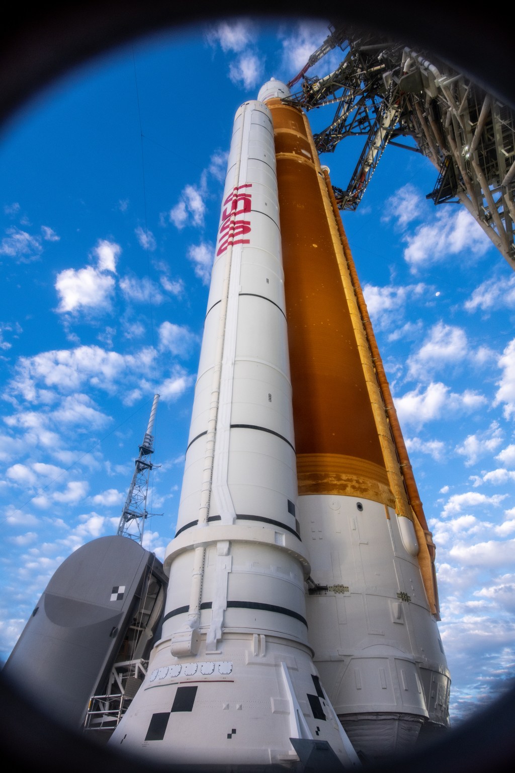
The Unitary Plan Wind Tunnel complex at Ames is one of the busiest wind tunnels at NASA today. It has played a vital role in testing generations of NASA’s aircraft and space vehicles from every crewed spaceflight program. The most recent projects to take essential steps forward in their design within these tunnel walls, include NASA’s newest X-plane – the quiet, supersonic X-59 – and NASA’s next great rocket – the Space Launch System – as well as the Orion capsule. It also is used to support the aerospace industry and government partners by testing commercial and military aircraft.
The two tunnel test sections have a unique capability to analyze models at the speed of sound and up to about 2.5 times faster, or at supersonic speeds. The complex features the “test section of the future” with large, specialized windows in the tunnel side walls, ceiling and floor that let researchers capture images for air flow visualization techniques. The Unitary Plan Wind Tunnel team recently used their years of experience testing the Orion capsule to help SpaceX design and run tests of their Dragon spacecraft, which successfully carried American astronauts to the International Space Station from American soil as part of NASA’s Commercial Crew Program.
National Full-Scale Aerodynamics Complex
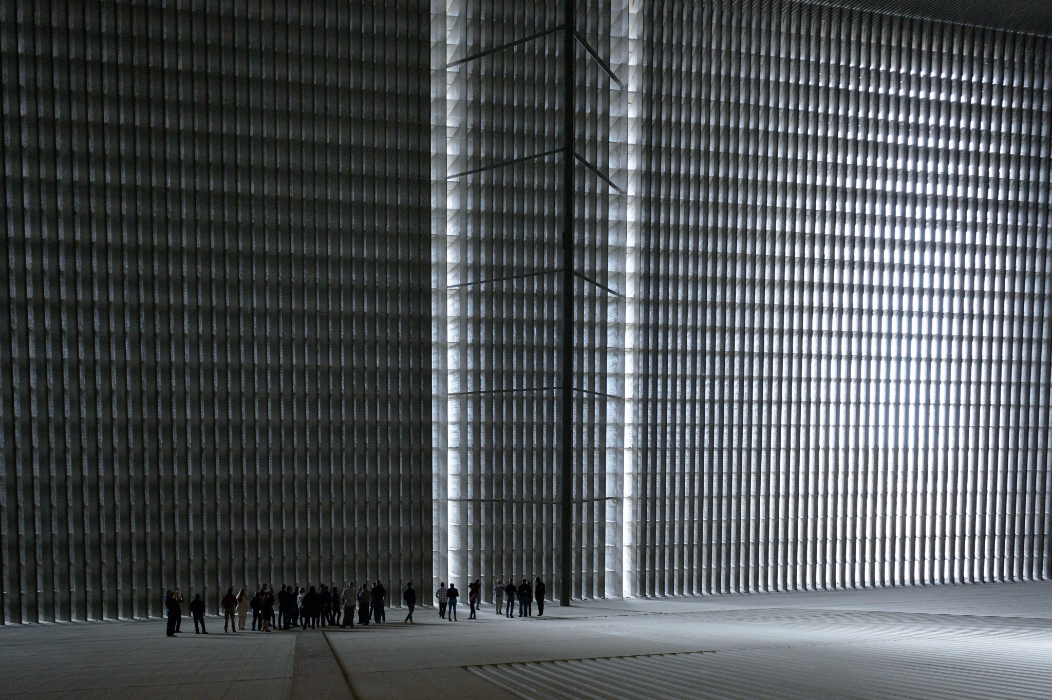
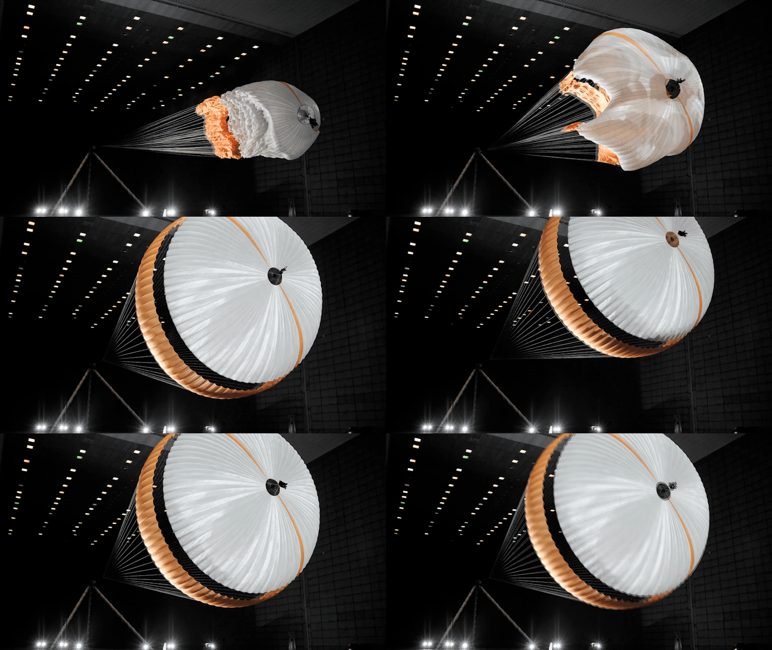
Home to the world’s two largest wind tunnels, the National Full-Scale Aerodynamics Complex at Ames is used to determine how air flows around full-scale vehicles and large-scale test models at speeds as fast as 115 miles per hour. The first test section, built by NACA in 1944, has a cross-sectional area of 40 feet by 80 feet. In 1987, NASA added the second tunnel test section, which measures 80 feet by 120 feet. The tunnels are managed and operated by the U.S. Air Force, and provide vital wind testing for some of the nation’s most sophisticated commercial and military aircraft, spacecraft, wind turbines, trucks and even the huge parachutes NASA uses to safely land rovers on Mars.
Learn More:
To ensure these materials and designs can get the job done, Ames researchers simulate atmospheric entry on the ground through testing. Specialized facilities within the Ames Arc Jet Complex simulate the aerothermodynamic heating that a spacecraft endures throughout hypersonic atmospheric entry to planets, and also tests potential thermal protection materials. In these facilities, chambers simulate entry conditions by artificially creating plasma at temperatures of about 3,000 degrees Fahrenheit and blasting it at high speeds against heat shield test models to see how they perform. This gives researchers the ability to simulate what the heat shield will experience during entry, providing data to improve and certify designs.
Fluid Mechanics Laboratory
Using the Fluid Mechanics Laboratory, engineers can predict how even minor alterations in shapes change flow patterns, which affects the performance of the vehicle. The 2-by 2-foot wind tunnel is capable of different speeds and releasing controlled smoke flow over surfaces, highlighted with laser light to increase flow visibility. The facility also features a 17-inch water channel, which uses florescent dye dispensed into the fluid flow under black lights, to show flow patterns.
Learn more:
Featured Examples
Supersonic Flight: Helping Us All Fly Faster
When an aircraft flies overhead faster than the speed of sound, people on the ground below hear a loud, startling sound, commonly called a sonic boom. These booms can be bothersome. Currently, commercial supersonic jets are limited to over-water routes. NASA, in partnership with Lockheed Martin, have been conducting groundbreaking research on piloted experimental aircraft and through recent wind tunnel tests and computational studies to help reduce the sonic boom to a much quieter “sonic thump” sound. The data gathered from these tests will pave the way for commercial supersonic flight over land and sea.
Learn more:
Advancing Rotor Designs with the Tiltrotor Test Rig
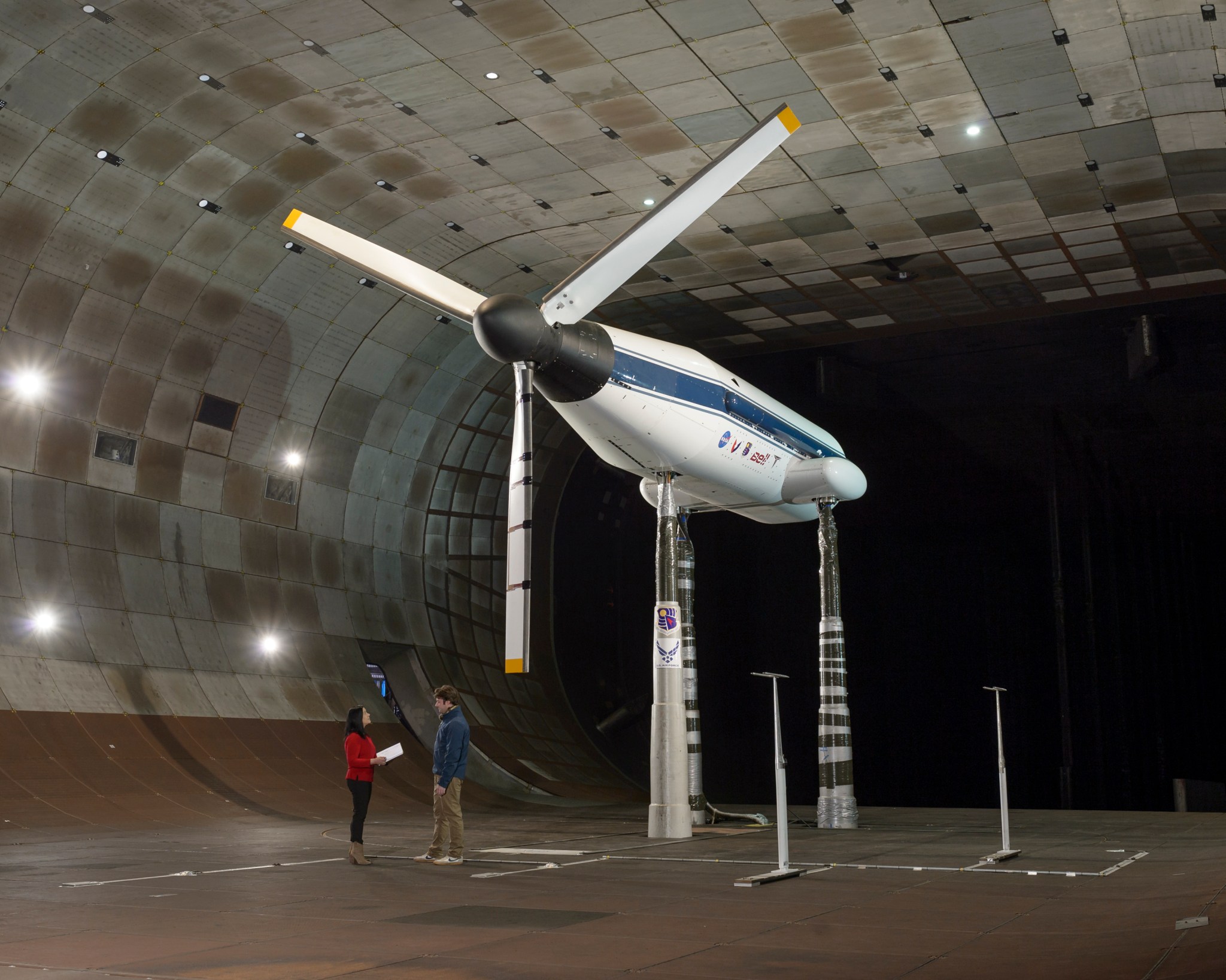
Tiltrotors are a type of aircraft capable of transitioning from vertical takeoff to forward flight. They will serve as an essential component for some of the craft used as air taxis in the future of Advanced Air Mobility. NASA developed the Tiltrotor Test Rig to study advanced rotor blade designs and behavior – like the blades helicopters use to fly – as large as 50 feet in diameter and up to speeds of 300 knots (345 miles per hour).
Learning to Land a Spacecraft on Mars
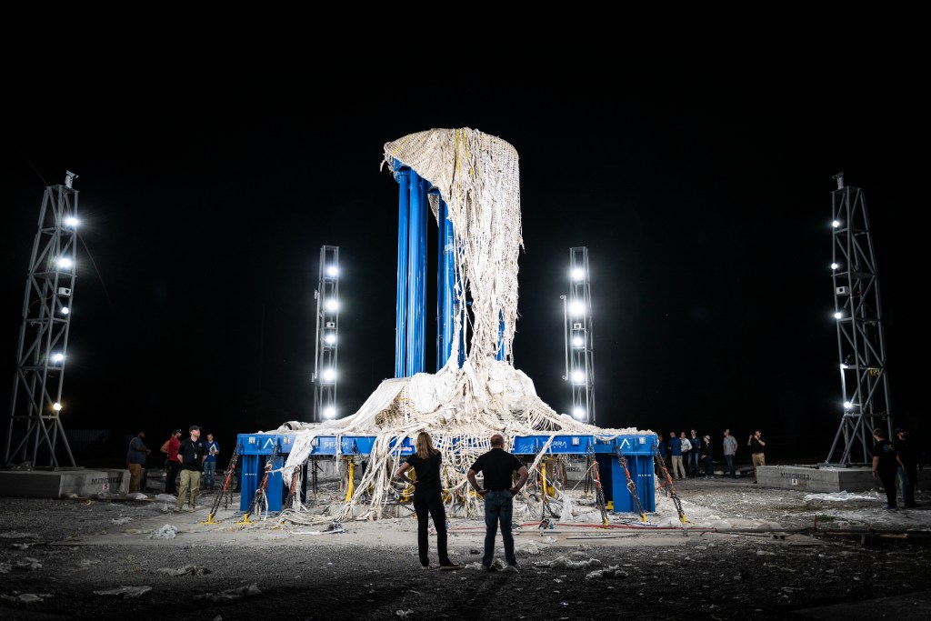
The huge capacity of the National Full-Scale Aerodynamics Complex wind tunnels made it possible to test the parachute that helped land NASA’s Mars Science Laboratory, including the Curiosity rover, on Mars. Engineers used the NFAC to test the redesigned and strengthened the parachute that the Mars 2020 spacecraft – carrying the Perseverance roverb deployed during entry into the Martian atmosphere in February 2021. Both parachutes measure more than 165 feet in length and open to a diameter of nearly 51 feet. The parachute is inflated at a low-speed on Earth to simulate the forces the system will need to withstand while entering Mars’ less-dense atmosphere.
The design for the parachute that will land the Mars 2020 spacecraft on the Red Planet was tested inside the world’s largest wind tunnel at the National Full-Scale Aerodynamics Complex. The parachute measures more than 165 feet in length and opens to a diameter of nearly 51 feet – with only about 12.5 feet of clearance to both the floor and ceiling.
Learn more:
Visualizing Shockwaves of Aircraft
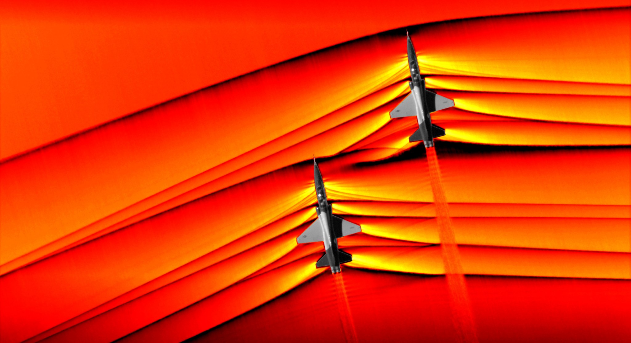
Airborne Background Oriented Schlieren Imaging (AirBOS) is a way to visualize the shockwaves and rapid pressure changes which are produced when an aircraft flies faster than the speed of sound, or supersonic . AirBOS works by flying a slow-moving observer airplane equipped with high-speed digital cameras, looking down at the landscape. The cameras record this landscape while awaiting the passage of the supersonic aircraft though the cameras’ fields-of-view. In the case of a supersonic aircraft, shock waves form and create highly compressed air disturbances around the vehicle. The air is so compressed that it bends the path of a ray of light. This bending, or distortion, changes the pattern the camera recorded before the plane entered its field of view. The images are then processed to calculate the amount of distortion the shockwaves caused to better understand how shocks interact with aircraft plumes, as well as with each other.
