


![Request for Information – Potential [Placeholder for Prize]](https://assets.science.nasa.gov/dynamicimage/assets/science/missions/a-step/FFR_Earth_Background_20251120%20.png?w=1024)


Chapter Contents
- Chapter Glossary
- 3.1 Introduction
- 3.2 State-of-the-Art – Power Generation
- 3.3 On the Horizon – Power Generation
- 3.4 State-of-the-Art – Energy Storage
- 3.5 On the Horizon – Energy Storage
- 3.6 State-of-the-Art – Power Management and Distribution
- 3.7 On the Horizon – Power Management and Distribution
- 3.8 Summary
- References
Chapter Glossary
| (AFRL) | Air Force Research Laboratory |
| (BMS) | Battery Management System |
| (BOL) | Beginning-of-Life |
| (CFRPs) | Composite Fiber Reinforced Panels |
| (CIGS) | Cu(In,Ga)Se2 |
| (COTS) | Commercial-off-the-Shelf |
| (EOL) | End-of-Life |
| (EPS) | Electrical Power System |
| (ESA) | European Space Agency |
| (GaN) | Galium Nitride |
| (GRC) | NASA Glenn Research Center |
| (KSC) | Kennedy Space Center |
| (Li-ion) | Lithium-ion |
| (LiCFx) | Lithium carbon monofluoride |
| (LiPo) | Lithium polymer |
| (LiSO2) | Lithium sulfur dioxide |
| (LiSOCl2) | Lithium thionyl chloride |
| (MIL) | Military |
| (QML) | Qualified Manufacturers List |
| (NiCd) | Nickel-cadmium |
| (NiH2) | Nickel-hydrogen |
| (OPV) | Organic Photovoltaic |
| (OSCAR) | Optical Sensors based on carbon materials |
| (PCB) | Printed Circuit Board |
| (PEASSS) | Piezoelectric Assisted Smart Satellite Structure |
| (PET) | polyethylene terephthalate |
| (PMAD) | Power management and distribution |
| (PV) | Photovoltaic |
| (RHUs) | Radioisotopic Heater Units |
| (RPS) | Radioisotope Power System |
| (RTGs) | Radioisotope Thermoelectric Generators |
| (SABER) | Solid-state Architecture Batteries for Enhanced Rechargeability and Safety |
| (SP) | Specific Power |
| (SWaP) | Size, Weight, and Power |
| (TPV) | Thermophotovoltaic |
| (TR) | Thermoradiative |
| (TRL) | Technology Readiness Level |
| (Wh kg) | Watt hours per kilogram |
3.1 Introduction
The electrical power system (EPS) is a major, fundamental subsystem that encompasses electrical power generation, storage, and distribution, and typically accounts for a significant portion of spacecraft volume and mass. Power generation technologies include photovoltaic cells, panels, and arrays, and radioisotope or other radioisotope thermoelectric generators (RTGs) . Power storage is typically applied through batteries; either single-use primary batteries or rechargeable secondary batteries. Power management and distribution (PMAD) systems facilitate power control to spacecraft electrical loads and take a variety of forms that are often custom designed to meet specific mission requirements. EPS engineers frequently target a high specific power or power-to-mass ratio (Wh kg−1) when selecting power generation and storage technologies to minimize system mass. For nanosatellites, EPS volume is often the primary design constraint.
Microsatellites (<200 kg) in low-Earth orbit (LEO) operate in relatively mild thermal and radiation environments, and therefore typically do not require extreme qualification standards or high Technology Readiness Levels (TRLs associated with deep-space missions). Engineers must carefully balance the differences between space-qualified parts (MIL/QML) and less stringent commercial off-the-shelf (COTS) components with mission-specific spacecraft requirements. Military or space-qualified components undergo rigorous testing—often certified for extreme temperatures (e.g., –55 °C to +125 °C), radiation tolerance, and long-term reliability—while COTS parts are usually rated for narrower ranges (–40 °C to +85 °C) and receive less comprehensive screening. While QML-qualified parts generally offer higher reliability, they are often limited in availability and subject to slow revision cycles. In contrast, COTS components typically provide better performance, quicker availability, and lower cost, making them well-suited for many small spacecraft applications.
CubeSat missions commonly use COTS parts due to their nearly exclusive operation in LEO, shorter mission durations, and more favorable environmental conditions, reducing the need for stringent qualification standards. Differences in EPS design between a ~150 kg spacecraft and a 10 kg CubeSat lie in priorities and constraints: CubeSats, with limited surface area, typically use fixed body-mounted solar cells, small batteries, and a single low-voltage bus. Conversely, a 150 kg microsatellite can support deployable solar panels, larger battery capacity with redundancy, and multiple regulated buses for power distribution. Both architectures can incorporate COTS components where mission risk permits.
This chapter reviews the following categories:
- Sections 3.2 & 3.3: Power Generation, including solar cells, panels, and arrays;
- Sections 3.4 & 3.5: Energy Storage, including Li-ion, supercapacitors, and solid-state batteries;
- Sections 3.6 & 3.7: Power Management, including modular architectures and wireless power transfer and telemetry.
The list of organizations/companies in this chapter is not all-encompassing and does not constitute an endorsement from NASA. The inclusion or omission of specific companies is not intended to reflect their technologies or relationship with NASA. The performance advertised may differ from actual performance as the information has not been independently verified by NASA subject matter experts and is based on manufacturer-provided or publicly available data. It should be noted that TRL designations may vary with changes specific to the payload, mission requirements, reliability considerations, and/or the environment in which performance was demonstrated. Readers are highly encouraged to reach out to companies for further information regarding the performance and TRL of the technology described.
3.2 State-of-the-Art – Power Generation
Power generation on microsatellites is typically governed by a common solar power architecture (solar cells + solar panels + solar arrays). As the SmallSat industry drives demand for lower cost and increased production rates, the photovoltaics industry is adapting to meet these needs. The standardization of solar array and panel designs, deployment mechanisms, and power integration will be critical to meet the desire for large, proliferated constellations.
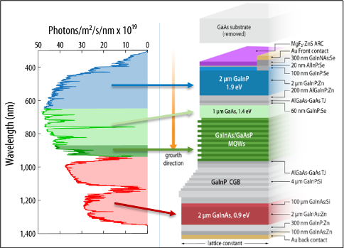
EPS engineers should note beginning-of-life (BOL) vs end-of-life (EOL) performance of the systems, as well as planned ground testing duration prior to operations. EPS for SmallSats is often overdesigned to accommodate dynamic thermal environments, eclipse durations in LEO, and varying sun-angles. Figure 3.1 captures actual space system performances given such wide varying operational conditions for 389 space missions (not only SmallSats) launched since 1989 to 2021 (1). The dotted horizontal line indicated where more of the 389 missions surveyed fall under.
When possible, choosing a pre-designed and qualified panel is preferred over designing unique solar panels to reduce the cost and schedule as well as unforeseen design and manufacturing issues. Companies that have the capacity for mass production and automation are rare because space solar arrays, cells, and panels have always been a ‘boutique’ business; however, standardized designs like the OneWeb and Starlink constellations have been appearing more often to meet the demands of highly proliferated constellations.
The following subsections aim to capture the current state of the art and assist EPS engineers, mission designers, system engineers, etc., in designing, reviewing and ultimately constructing and operating power flight systems.
3.2.1 Solar Cells
Solar power generation is the predominant energy source for small spacecraft, with more than 90% of all nanosatellite/SmallSat form factors equipped with solar panels and rechargeable batteries (1). Photovoltaic (PV) cells, or solar cells, are made from thin semiconductor wafers that produce an electric current when exposed to light. The amount of light available to a spacecraft solar array— also called solar intensity—varies with the inverse square of the distance from the Sun. Power generation is predicated primarily by the angle of incidence to the sun. Perpendicular orientation provides maximum generation which then drops off by the cosine of the angle as the solar array is tilted away from the sun.
A basic solar cell is made from a single layer of semiconductor material (most commonly Silicon, Si) that has been doped with boron and phosphorus to create a bandgap to convert sunlight into electricity. These single-junction cells are inexpensive to manufacture but have relatively low efficiencies, around 20%. Single-junction cells are best at converting light within a narrow wavelength range and are primarily used in missions with short lifetimes or are cost sensitive and are not covered here.
By contrast, multi-junction solar cells are constructed by stacking multiple semiconductor layers, each with an optimized bandgap tuned to absorb a specific portion of the solar spectrum. This layered structure enables the cell to convert a broader range of sunlight into electricity more efficiently (minimal heat loss), achieving spectral efficiencies of 30-34% (2)(3). While the theoretical efficiency limit for an infinite-junction cell under concentrated sunlight is 86.6%, real-world performance is constrained by optical and thermal losses, semiconductor material imperfections, and electrical and thermal effects within the materials. A multi-junction cell that (4) contains only two different semiconductor materials is known as a tandem-junction cell, and there has been high interest in a hybrid-tandem cell where two different solar cell technologies are combined so energy can be more efficiently generated by separate devices (5).
The current state-of-the-art for space solar cells includes 3- to 5- junction architectures based on Group III-V semiconductor elements (like GaAs, InGaP, and Ge) with a nominal efficiency of 30% and a high of 34%. While this concept is well-established, research seeks to optimize power conversion efficiency with different combination of materials and adjusting the manufacturing process. Some modern designs include 4- to 5- junctions by adding materials like InGaAs, AlGaAs, or GaInNAs; tandem layers of perovskite on the III-V stacks are also being investigated (see Section 3.3).
Despite their advantages, solar cells face several limitations for space applications. These include reduced effectiveness in deep-space environments, lack of power generation during eclipse periods, and performance degradation over the mission lifetime (due to aging, radiation, and contamination). Solar cells also contribute significantly to spacecraft mass, surface area, and cost. To increase power generation within the limited volume of microsatellites, deployable solar panels are often used, though this increases spacecraft design complexity, reliability, and risk. Ultimately for a small spacecraft, the size, weight, and volume constraints may drive the choice of solar cell technology rather than solar cell efficiency. Since solar arrays are life-limiting components, their EOL performance at operating temperature is a critical metric. Common degradation factors include radiation exposure, coverglass or adhesive darkening, surface contamination, and mechanical or electrical failures.
Table 3-1 itemizes small spacecraft solar cell efficiency per the available manufacturers. Note the efficiency may vary depending on the solar cells chosen.
| Table 3-1: Solar Cells | |||||||
|---|---|---|---|---|---|---|---|
| Manufacturer Headquarters | Cell Name | BOL Efficiency | Voc (V) | Vmp (V) | Jsc (mA/ cm2) | Jmp (mA/ cm2) | Pmp (W/m2) |
| AZUR Space Germany | Silicon S 32 | 16.8 | 0.628 | 0.528 | 45.8 | 43.4 | 229.2 |
| 3G30-Adv | 29.5 | 2.7 | 2.411 | 17.2 | 16.71 | 403 | |
| 4G32-Adv | 31.5 | 3.426 | 2.999 | 15.2 | 14.37 | 431 | |
| TJ 3G28C | 28 | 2.667 | 2.37 | 16.77 | 16.14 | 1367 | |
| Rocket Lab USA | ZTJ | 29.5 | 2.726 | 2.41 | 17.4 | 16.5 | 397.7 |
| ZTJ+ | 29.4 | 2.69 | 2.39 | 17.1 | 16.65 | 397.9 | |
| ZTJ Omega | 30.2 | 2.73 | 2.43 | 17.4 | 16.8 | 408.2 | |
| Z4J | 31.3 | 3.95 | 3.54 | 12 | 11.5 | 407.1 | |
| IMMα | 32.0 | 4.78 | 4.28 | 10.7 | 10.12 | 433.1 | |
| ZTJM | 29.5 | 2.72 | 2.38 | 17.1 | 16.5 | 392 | |
| Boeing-SpectroLab USA | XTJ | 29.5 | 2.633 | 2.348 | 17.76 | 17.02 | 399.6 |
| XTJ-Prime | 30.7 | 2.715 | 2.39 | 18.1 | 17.4 | 415.9 | |
| XTE-SF | 32.2 | 2.75 | 2.435 | 18.6 | 17.8 | 433.4 | |
| XTE-HF | 32.1 | 2.782 | 2.49 | 18 | 17.4 | 427.9 | |
| XTE-LILT | 31.6 | 2.755 | 2.459 | 18.1 | 17.4 | 427.9 | |
| UTJ | 28.4 | 2.66 | 2.35 | 17.14 | 16.38 | 384.93 | |
| TASC | 27 | 2.52 | 2.19 | 32 | 28 | 270 | |
| ITJ | 26.8 | 2.565 | 2.27 | 16.9 | 16 | 1353 | |
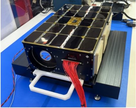
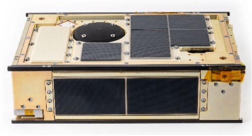
3.2.2 Solar Panels & Arrays
Solar panels and arrays are constructed from individual solar cells connected in series to form strings and in parallel to form circuits mounted on a substrate backing. Figure 3.2 has a few examples of 6U spacecraft with solar panels. While very low-power CubeSats and SmallSats may only need body-mounted solar panels, most will require more power from deployed solar arrays. The deployed solar arrays for CubeSats and SmallSats are mostly on rigid substrates made of either a printed circuit board (PCB), composite fiber reinforced panels (CFRPs), or an aluminum honeycomb panel.
Deployed solar arrays are often the largest structure on a satellite. The ratio of deployed solar array size to spacecraft size is often significantly higher than for traditional spacecraft. The size and fundamental frequency of the solar arrays impact spacecraft pointing, propulsion, and delta-
V needed for station keeping. Important considerations for SmallSat solar arrays are deployment mechanisms, deployed frequency, panel specific power, and power density, as well as stowed volume. Most of these metrics are not listed on manufacturer datasheets.
Solar array comparison can be challenging because manufacturers who make solar arrays specific to their bus and payload designs often do not report solar array power using the same metrics. Reported “power” can refer to multiple metrics: power available to the payload, peak power provided by a combination of solar array and battery, or an orbital-specific average power. Reported solar array power (Peak BOL) mainly refers to the peak power of the solar array at the beginning of life at standard test conditions (e.g., ~28°C), which is mission independent. Panel stiffness and moment of inertia usually need to be calculated for a specific spacecraft because they are dependent on multiple factors such as the size and mass of the panel, as well as spacecraft size and weight distribution. Examples of commercial solar array and panel products are shown in Table 3-2; information is from company websites and technology datasheets.
| Table 3-2: Solar Array/Panel Products | ||||
|---|---|---|---|---|
| Company Headquarters | Product | Panel Type | Specific Power (W/kg) | Peak BOL Solar Array Power (W) |
| AAC Clyde Space Sweden | Photon | * | * | 9.25 / 3U-12 Face |
| 2NDSpace Italy | DROP-03X | Double Deployable | 62.5 | 22.5 |
| DROP-04X | Double Deployable | 62.5 | 30 | |
| DROP-12 | Deployable | 70 | 40 | |
| DROP-03XL | Triple Deployable | 67.5 | 30 | |
| CORE-01Z | Body Mounted | 65 | 2.45 | |
| CORE-01 | Body Mounted | 70 | 2.45 | |
| CORE-02 | Body Mounted | 65 | 4.88 | |
| CORE-03 | Body Mounted | 72.5 | 8.54 | |
| CORE-04 | Body Mounted | 75 | 11 | |
| CORE-06Z | Body Mounted | 55 | 4.88 | |
| CORE-12 | Body Mounted | 67.5 | 19.52 | |
| CORE-12Z | Body Mounted | 50 | 9.76 | |
| CORE-16 | Body Mounted | 62.5 | 24.4 | |
| Agencia Espacial Civil Ecuatoriana Italy | Deployable Multifunction Solar Array | Deployed Rigid | – | – |
| Airbus Netherlands The Netherlands Airbus Netherlands The Netherlands Airbus Netherlands The Netherlands | Sparkwing Solar Panel 600x570mm 36V | Body Mounted, 1-3 deployed panels, Rigid | 18 | 88 per panel |
| Sparkwing Solar Panel 600x700mm 36V | Body Mounted, 1-3 deployed panels, Rigid | 21 | 111 per panel | |
| Sparkwing Solar Panel 600x820mm 36V | Body Mounted, 1-3 deployed panels, Rigid | 24 | 133 per panel | |
| Sparkwing Solar Panel 600x965mm 36V | Body Mounted, 1-3 deployed panels, Rigid | 25 | 155 per panel | |
| Sparkwing Solar Panel 750x820mm 36V | Body Mounted, 1-3 deployed panels, Rigid | 29 | 177 per panel | |
| Sparkwing Solar Panel 750x965mm 36V | Body Mounted, 1-3 deployed panels, Rigid | 30 | 199 per panel | |
| Sparkwing Solar Panel 750x1100mm 36V | Body Mounted, 1-3 deployed panels, Rigid | 34 | 243 per panel | |
| Sparkwing Solar Panel 910x820mm 36V | Body Mounted, 1-3 deployed panels, Rigid | 33 | 221 per panel | |
| Sparkwing Solar Panel 910x965mm 36V | Body Mounted, 1-3 deployed panels, Rigid | 37 | 265 per panel | |
| Sparkwing Solar Panel 1000x570mm 36V | Body Mounted, 1-3 deployed panels, Rigid | 29 | 176 per panel | |
| Sparkwing Solar Panel 1000x1100mm 36V | Body Mounted, 1-3 deployed panels, Rigid | 39 | 309 per panel | |
| Sparkwing Solar Panel 1070x820mm 36V | Body Mounted, 1-3 deployed panels, Rigid | 37 | 265 per panel | |
| Sparkwing Solar Panel 600x570mm 50V | Body Mounted, 1-3 deployed panels, Rigid | 19 | 92 per panel | |
| Sparkwing Solar Panel 600x800mm 50V | Body Mounted, 1-3 deployed panels, Rigid | 22 | 122 per panel | |
| Sparkwing Solar Panel 600x965mm 50V | Body Mounted, 1-3 deployed panels, Rigid | 25 | 153 per panel | |
| Sparkwing Solar Panel 600x1100mm 50V | Body Mounted, 1-3 deployed panels, Rigid | 28 | 183 per panel | |
| Sparkwing Solar Panel 750x570mm 50V | Body Mounted, 1-3 deployed panels, Rigid | 23 | 122 per panel | |
| Sparkwing Solar Panel 750x800mm 50V | Body Mounted, 1-3 deployed panels, Rigid | 25 | 153 per panel | |
| Sparkwing Solar Panel 750x965mm 50V | Body Mounted, 1-3 deployed panels, Rigid | 36 | 241 per panel | |
| Sparkwing Solar Panel 750x1100mm 50V | Body Mounted, 1-3 deployed panels, Rigid | 34 | 244 per panel | |
| Sparkwing Solar Panel 910x570mm 50V | Body Mounted, 1-3 deployed panels, Rigid | 26 | 153 per panel | |
| Sparkwing Solar Panel 910x800mm 50V | Body Mounted, 1-3 deployed panels, Rigid | 32 | 214 per panel | |
| Sparkwing Solar Panel 910x965mm 50V | Body Mounted, 1-3 deployed panels, Rigid | 34 | 244 per panel | |
| Sparkwing Solar Panel 910x1100mm 50V | Body Mounted, 1-3 deployed panels, Rigid | 40 | 305 per panel | |
| Sparkwing Solar Panel 1070x570mm 50V | Body Mounted, 1-3 deployed panels, Rigid | 29 | 183 per panel | |
| Sparkwing Solar Panel 1070x800mm 50V | Body Mounted, 1-3 deployed panels, Rigid | 34 | 244 per panel | |
| Sparkwing Solar Panel 1070x965mm 50V | Body Mounted, 1-3 deployed panels, Rigid | 39 | 305 per panel | |
| Sparkwing Solar Panel 1070x1100mm 50V | Body Mounted, 1-3 deployed panels, Rigid | 45 | 366 per panel | |
| Sparkwing Solar Panel 1230x570mm 50V | Body Mounted, 1-3 deployed panels, Rigid | 31 | 214 per panel | |
| Sparkwing Solar Panel 1230x800mm 50V | Body Mounted, 1-3 deployed panels, Rigid | 36 | 275 per panel | |
| Blue Canyon Technologies USA | BCT Solar Array | Body Mount + Deployed Rigid | * | 28 – 42 for 3U / 48-118 for 6U-12U |
| DHV Technologies Spain DHV Technologies Spain DHV Technologies Spain | DSA-042W | Simple Deployable Wing | 36 | 42 |
| BMSA-066W | Body Mounted | 68 | 66 | |
| DSA-079W | Simple Deployable Wing | 43 | 80 | |
| BMSA-050W | Body Mounted | 65 | 50 | |
| DSA-079W | Simple Deployable Wing | 44 | 95 | |
| DSA-108W | Simple Deployable Wing | 50 | 109 | |
| BMSA-087W | Body Mounted | 68 | 87 | |
| DSA-183W | Double Deployable Wing | 50 | 183 | |
| DSA-185W | Simple Deployable Wing | 56 | 185 | |
| DSA-255W | Double Deployable Wing | 60 | 256 | |
| BMSA-366W | Body Mounted | 52 | 366 | |
| DSA-373W | Double Deployable Wing | 41 | 373 | |
| DSA-555W | Triple Deployable Wing | 60 | 556 | |
| DSA-686W | Quadruple Deployable Wing | 34 | 676 | |
| DSA-898W | Quintuple Deployable Wing | 34 | 889 | |
| DSA-1268W | Sextuple Deployable Wing | 46 | 1268 | |
| DHV-1U Series (Body Mounted) | PCB Substrate (Polyimide) | 41 | 2 | |
| DHV-2U Series (Body Mounted) | PCB Substrate (Polyimide) | 44 | 4 | |
| DHV-3U Series (Body Mounted) | PCB Substrate (Polyimide) | 56 | 8 | |
| DHV-6U Series (Body Mounted) | PCB Substrate (Polyimide) | 60 | 18 | |
| DSA-3U-1D-L (Simple Deployable Wing) | PCB Substrate (Polyimide) | 33 | 7 | |
| DSA-3U-2D-L (Double Deployable Wing) | PCB Substrate (Polyimide) | 35 | 11 | |
| DSA-3U-3D-L (Triple Deployable Wing) | PCB Substrate (Polyimide) | 46 | 21 | |
| DSA-6U-1D-L (Simple Deployable Wing) | PCB Substrate (Polyimide) | 67 | 28 | |
| DSA-6U-1D-S (Simple Deployable Wing) | PCB Substrate (Polyimide) | 35 | 19 | |
| DSA-6U-2D-S (Double Deployable Wing) | PCB Substrate (Polyimide) | 67 | 55 | |
| DSA-6U-2D-L (Double Deployable Wing) | PCB Substrate (Polyimide) | 66 | 41 | |
| EmxysSpain | 3U Solar panel: 327.5x83x 2.2mm, 14.7V | Body Mounted (Rigid Polyimide) | 66.6 | 8.2 |
| 6U Solar panel: 226.3x366x2.2mm, 33.6V | Body Mounted (Rigid Polyimide) | 53.3 | 17.6 | |
| EnduroSat Bulgaria | 3U Solar Panel/Array | Deployed Rigid | 66 | 14.4 |
| 6U Solar Panel/Array | Deployed Rigid | 64 | 19.2 | |
| 8U Solar Panel/Array | Deployed Rigid | 65 | 24.0 | |
| Exobotics United Kingdom | XO-PANEL 1U | Body Mounted | 46 | 2.3 |
| XO-PANEL 2U | Body Mounted | 46 | 4.6 | |
| XO-PANEL 3U | Body Mounted | 54 | 8.1 | |
| XO-PANEL 6U | Body Mounted | 62 | 27.8 | |
| ExoTerra Resource USA | Fold Out Solar Arrays (FOSA) | Deployed Flexible | 140 | 150 |
| GomSpace Denmark | Nanopower DSP | Deployed Rigid | * | 1.2 |
| NanoPower P110 | Fixed | 36.9 – 92 | 1.2 / cell 2.4 | |
| NanoPower MSP 16 cell | Fixed | 42 | 1.2 /cell 19.2 | |
| NanoPower TSP Per wing | Deployed Rigid | 60 | 45 | |
| ISISPACE The Netherlands | Smallsat Solar Panels | Body Mount + Deployed Rigid | 46 | 2.3 / U |
| Lockheed Martin USA | SmallSat Solar Array | Deployed Rigid with Additively Manufactured Substrate | 53.6 | 170 / panel BOL at 28C |
| MMA Design USA | Hawk | Deployed Rigid (PCB) | 121 | 36-112 |
| zHawk | Deployed Rigid (PCB) | 95 | 36 | |
| Next-Gen HaWK | Deployed Rigid (PCB) | 100 | 45 – 310 | |
| NPC Spacemind Italy | SP1X | Body Mounted 1U | 68 | 2.4 |
| SP1Z | Body Mounted 1U Top | 68 | 2.4 | |
| SP2X | Body Mounted 2U | 64 | 4.8 | |
| SP2Z | Body Mounted 2U Top | 64 | 4.8 | |
| SP3X | Body Mounted 3U | 76 | 8.4 | |
| SP4X | Body Mounted 4U | 75 | 10.8 | |
| SP4Z | Body Mounted 4U Top | 58 | 9.6 | |
| SP6X | Body Mounted 6U | 74 | 19.2 | |
| SP8X | Body Mounted 8U | 68 | 24 | |
| SP3X Deployable | Double wing Deployable 3U | 75 | 21.6 | |
| SP4X Deployable | Double wing Deployable 4U | 58 | 28.8 | |
| SP6X Deployable | Double wing Deployable 6U | 74 | 57.6 | |
| SP8X Deployable | Double wing Deployable 8U | 68 | 72 | |
| Pumpkin Space Systems USA | Dual Articulated Deployable Solar Array | Deployed Rigid | 31 | 135 |
| Dual-Quad Articulated Deployable Solar Array | Deployed Rigid | 30 | 240 | |
| Deployable Clamshell Solar Array (DCSA) | Deployed Rigid | 44 | 220 | |
| Deployable Clamshell Solar Array (DCSA) | Deployed Rigid | 38 | 350 | |
| Redwire Space USA | ROSA | Flexible PV blanket | 100 | 1000 |
| Aladdin SmallSat Array | Hybrid Array: Flex Rigid | 80 | 300 | |
| SatRev S.A. Poland | Deployable panel | Custom size deployable 3U – 6U | 40 | 36 for a typical 6U deployment |
| Sierra Space Corp USA | Surface Mount Technology Solar Panel | Composite | – | 2500 |
| Space Dynamics Laboratory USA | SDL Modular Solar Panels | Deployed Rigid | 84.5 | 180 / panel |
| Spacemanic Czech Republic | RA Solar Panels | Triple Junction GaAs | 38.55 | 19.2 |
| * Available with inquiry to manufacturer ** For SmallSat use | ||||
While solar efficiency has been the prevailing way to characterize solar array performance, discrepancies between theoretical and empirical data indicate that specific power (SP) of the solar array fundamentally governs space mission feasibility and flexibility. Figure 3.3 visualizes the landscape of mission architectures, parameterized by power (adjusted by a factor of squared distance) and mass; the relation between these axes is the SP.
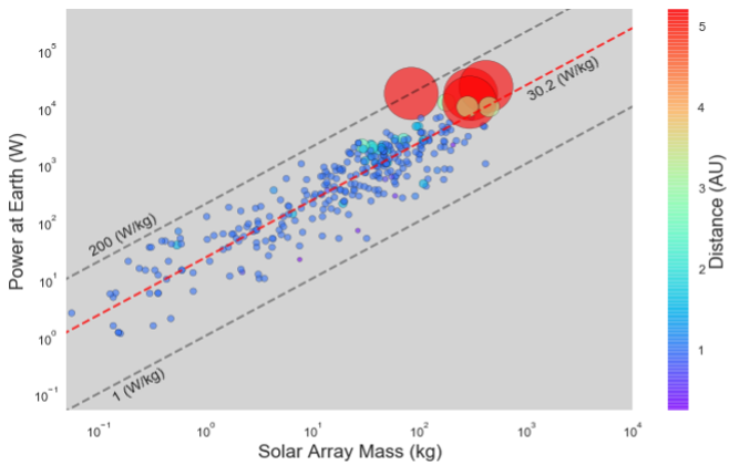
Space missions using solar arrays, regardless of spacecraft mass, are strongly clustered around ~30 W/kg (red dashed line) and are strongly bounded: no missions fly with SP lower than 1 W/kg (lower dashed line), and the maximum empirical SP of this dataset is 200 W/kg (upper dashed line). There are two clearly unoccupied regions: the empty region of high-mass and low-power is of little interest since this is not generally desirable; however, it is interesting that the high-power low-mass regime is empty, indicating that while this is a highly desirable region, it is technologically inaccessible.
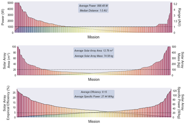
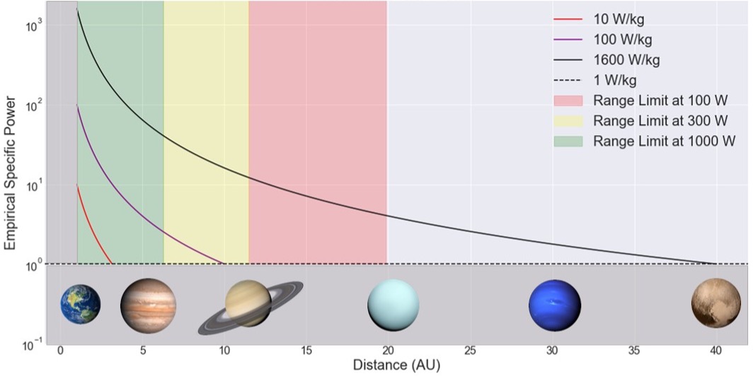
With the average mission power consumption of 1000 W and a medium value of 600 W, Figure 3.4 shows what maximal ranges can be achieved with three hypothetical solar array technologies with specific power levels of 10, 100 and 1600 W/kg (the lines show how the Empirical Specific power changes as a function of range until it reaches the lower limit of 1 W/kg). The color-coded regions are where maximal surface area of 100 m2 could be contained for power levels of 100, 300, and 1000 W. The areas under the line and within the colored region indicate where current (empirical evidence) and future (theoretical) missions could exist.
There are two possible approaches to improving solar array specific power: increase generated power or decrease array mass. The former has been the focus of the community for the past 40 years through improving efficiencies. However, even if triple-junction solar cell efficiency improves to the theoretical limit of approximately 40%, the surface area, mass, and storage volume required to support median power requirements for exploration of deep space are beyond the point of feasibility. The mass required from such solar array structures would be measured in thousands of kilograms; clearly a reduction in solar array mass is needed for deep space exploration missions to be feasible.
Future work is needed to reduce solar array mass; deployment mechanism mass could be reduced with light-weight components or alternate configurations (for example, using a tension-based deployment instead of a motor-driven system) to eliminate the requirement for a motor and many spacecraft integration components. Mass reduction for the solar cells themselves can come by reducing cell thickness or increasing flexibility to increase launch vehicle stowage volume. Creating highly foldable arrays may be a desirable solution, with mass decreases possible in both deployment mechanisms and in the design of solar cells.
3.3 On the Horizon – Power Generation
The global surge in renewable energy research has significantly advanced materials science, particularly in the development of next generation power systems for small spacecraft. Innovations like advanced single-junction, multi-junction, flexible and organic solar cells are at the forefront of this progress. These technologies are poised to surpass the current state of the art in aerospace solar power, especially as their high efficiencies—demonstrated under terrestrial sunlight—are adapted for space environments. Other promising power sources such as hydrogen fuel cells, thermonuclear systems, and atomic batteries are beyond the scope of this chapter and are not discussed here.
3.3.1 Multi-junction Solar Cells
There is ongoing research and development to improve aerospace use of multi-junction solar cell technology, and recent progress within terrestrial photovoltaic applications indicates significant progress. Advancements for multi-junction cells include enhanced crystal growth techniques, studying the geometric orientation in nanostructures, improved matching the layers electrical currents, and better radiation tolerance and thermal stability.
Fraunhofer Institute for Solar Energy Systems contributed to the development a four-junction solar cell that achieved a significant 47.6% efficiency under concentrated sunlight (ideal case) using an advanced antireflection coating and optimized contact layers; and the demonstration of Si-based multi-junction solar cells with 36.1% efficiency. Future investigations are needed to solve current challenges of the complex inner structure of the layers (6).
The National Laboratory of the Rockies (NRL, previously National Renewable Energy Laboratory, NREL) has actively advanced photovoltaic technology with their suite of characterization tools for analyzing proton and electron radiation effects. Figure 3.5 below shows a cross section of a IMM solar cell by NRL. They have advanced modern photovoltaic technology, with 4- and 6-junction cells achieving or exceeding 35–38% in the lab and even reaching 47.1% under concentrated illumination for a 6-junction III-V device (8). NRL’s latest developments with their dual chamber Dynamic Hydride Vapor Epitaxy (D-HVPE) growth reactor for manufacturing scalable III-V cells achieved 27% efficiency GaAs single-junction under terrestrial sunlight, which is exciting since its very likely the efficiency in space will be only a slightly lower though much higher than the current 20% nominal (9).
Perovskite Cells
Emerging progress of perovskite technology solar cells is happening across the globe in academic institutions, R&D labs, and industry. Known for its exceptional photo-electric properties (high power-to-mass ratio, high efficiency potential, and high optical absorption) and flexibility, perovskite solar cells can convert more sunlight into energy. Major limitations are degradation, insufficient long-term stability, and durability when exposed to harsh space radiation over longer periods of time.
Perovskite materials are ideal for creating multi-junction solar cells since their electronic properties can be adjusted by altering their composition (10). Currently, the University of Science and Technology of China achieved 26.7% efficiency of a single-junction perovskite solar cell under terrestrial sunlight (11). Researchers have found that when used in tandem with other materials, Silicon being the most common, perovskite cells achieve significantly increased efficiency. LONGi company developed a crystalline silicon-perovskite tandem solar cell with 34.85% efficiency (terrestrial) and is inching closer to space demonstration.
In a collaboration with JAXA, the Ricoh Company aims to achieve practical applications of perovskite solar cells. In October 2025, Ricoh perovskite solar cells were installed on the unmanned cargo transfer spacecraft1, HTV-X1, onboard the ISS, where they are exposed for two months (12). On the same launch, Aegis Aerospace’s MISSE-21 mission were halide perovskite-based cells from Georgia Institute of Technology. Instead of using silicon, researchers from Georgia Tech’s School of Materials Science and Engineering develop ways to prevent the degradation of perovskite cell and promote resiliency by mixing chemistries of the materials (13)(14).
Flexible Solar Cells
Flexible and thin-film solar cells have an extremely thin layer of photovoltaic material placed on a substrate of glass or plastic; flexible substrates now also include advanced polymers and ultra-thin glass. The thickness of photovoltaic layers using modern crystalline silicon wafers are typically 100–200 microns and the thin-film layers range from <1 to a few microns depending on the material. This allows the cells to be flexible, lightweight, and cheaper to manufacture because they use less raw material. Limitations with implementing thin-film solar technology in space are the manufacturing complexity, temperature sensitivity, and reduced durability and overall power efficiency.
Recent research in thin-film solar technology is being conducted by institutions like the Korea Institute of Energy Research (KIER), Uppsala University, and Helmholtz-Zentrum Berlin often in tandem with perovskite cells for better efficiency. Researchers at KIER combined copper indium gallium selenide (CIGS) and perovskite cells and achieved a power conversion efficiency of 23.64% (16)(15). CIGS semiconductor material is a highly efficient light absorber, and active research at Uppsala University in Sweden is investigating a variety of implementation and manufacturing techniques to maximize the solar cell efficiency (17).
Organic Solar Cells
Carbon-based organic photovoltaic technology is another outlet for the next generation aerospace power generation. Organic electronics, polymers, or molecules absorb light and create a corresponding charge. A small quantity of these materials can absorb a large amount of light making them cheap, flexible, and lightweight. Improvements to organic solar cells’ durability and lifespan for aerospace use are actively being developed and tested. Currently at the laboratory level, organic solar cells achieve ~20% power conversion efficiency and there are promising advancements in organic semiconducting materials and improved manufacturing strategies (18).
Researchers at the University of Michigan are studying how radiation affects different organic solar cell designs, with the goal of identifying potential approaches to mitigate degradation in complex polymer-based cells. The team identified a “trap effect” where proton exposure can damage organic solar cells by breaking side chains and creating electron traps, capturing electrons that would otherwise generate electricity. The team found that heating the cells (thermal annealing) can repair cell damage, and they believe sun-facing solar cells in space could potentially self-heal through natural heating (19).
No standardized stability tests are yet available for organic-based solar cell technology, and challenges remain in creating simultaneous environmental influences that would permit an in-depth understanding of organic photovoltaic behavior, but these achievements are enabling progress in organic-based solar cell use .
3.3.2 Unitized Regenerative Fuel Cells
A primary fuel cell can be seen as an energy generation system in that it takes consumable products, typically H2 and O2, to create electricity and water. This reaction is in a single direction, complete when all reactants are consumed. Fuel cells for energy storage are appealing for their lightweight, reliable qualities, and high energy conversion efficiency capabilities. They also allow missions to launch with a safe, storable, low-pressure, and non-toxic fuel source, making them more ideal for interplanetary missions and during eclipse periods. Primary hydrogen fuel cells cannot be recharged and are not feasible for small spacecraft, though there is active development for secondary regenerative fuel cells with promising applications in aerospace and military systems.
Like a rechargeable battery, unitized regenerative fuel cells (URFCs) is a single device that can store and generate energy by transitioning between fuel cell (discharging) and electrolysis (charging) modes. Researchers have experimented with different proton exchange membranes to separate the hydrogen and electrolyzer finding that polymer electrolyte membrane fuel cells could be well suited for space applications (20). The round-trip efficiency is a combination of the electrolysis and fuel cell processes and varies depending on the specific material technology and operating conditions.
Main limitations include designing the electrocatalyst to perform well under extreme operating conditions (i.e., high voltage) in water electrolysis and self-regenerate; achieving appropriate thermal management for the two different operating temperatures; and proper management of water during each operation (electrolysis and fuel cell).
3.4 State-of-the-Art – Energy Storage
Solar energy is not always available during spacecraft operations due to orbital dynamics, mission duration, distance from the Sun, and peak load demands, so spacecraft require onboard energy storage usually via batteries. Batteries are classified by electrochemistry; primary (non-rechargeable) and secondary (rechargeable) batteries, are each suited to different mission needs. Today, lithium-based primary batteries such as lithium sulfur dioxide (LiSO₂), lithium carbon monofluoride (LiCFₓ), and lithium thionyl chloride LiSOCl₂ are preferred for their high energy density; silver-zinc batteries are now considered legacy systems. Since their lifespan is low, primary batteries are commonly applied in short mission durations and are not currently considered state-of-the-art energy storage systems. Therefore, the rest of this section will focus on secondary batteries only, with some exceptions.
Secondary-type batteries such as lithium-ion (Li-ion) and lithium polymer (LiPo) are now the standard for modern aerospace and commercial applications, replacing older nickel-based chemistries like nickel-cadmium (NiCd) and nickel-hydrogen (NiH2). Li-ion batteries use organic liquid electrolytes and can reversibly convert electrical energy to chemical energy, making them rechargeable, lightweight, and energy-dense—ideal for portable electronic devices, small tools, and in spacecraft missions. In space missions, these batteries are often paired with a primary energy source (e.g., solar arrays) to provide reliable, rechargeable power. For missions requiring short, intense energy bursts, secondary batteries may also be preferred since they can reduce overall system weight and still provide high power.
The primary limitation of high-power cells is safety. The manufacturing process of Li-based batteries use flammable, liquid electrolytes that can trigger thermal runaway, potentially leading to fire or explosion. This can occur due to several causes: damage, overheating, overcharging, water exposure, or manufacturing defects. In space, the onboard energy storage must endure extreme temperature fluctuations and high charge voltages, which accelerates degradation. Over time, repeated charge/discharge cycles reduce total energy output (measured in Watt-hours). Variables influencing this aging include temperature, charge/discharge rate, depth of discharge, and storage conditions. These factors make life testing under mission-specific conditions essential before launch to ensure the battery will meet the specific mission life requirements.
3.4.1 Secondary Li-ion BAtteries
Rechargeable batteries are ubiquitous in small spacecraft, and the space industry has seen incremental improvements in energy density over time. A high gravimetric energy density (energy per unit mass) enables lighter batteries with equal or greater capacity, helping to minimize launch costs. Although battery selection for small spacecraft must consider more than just energy density—safety, cycle life, power output, and environmental resilience are all equally vital.
Recent advancements include the incorporation of silicon in anodes, high-voltage cathodes, novel electrolyte additives, and improved cell designs. This section reviews individual cell chemistries and pre-assembled batteries from various manufacturers, each leveraging different lithium-based chemistries to optimize weight and energy density. Table 3-3 lists battery pack products, organized by specific energy to align with mass and volume constraints of the spacecraft.
Li-ion battery manufacturing is concentrated among a relatively small number of companies. Listed in Table 3-3 are companies at the forefront of their respective sectors. While China has some of the largest consumer electronics and EV battery manufacturers, their products are less established in the space industry and are not included here.
| Table 3-3: Commercial and Space Li-ion Manufacturers | |||
|---|---|---|---|
| Commercial Li-ion Manufacturing | Space Li-ion Manufacturing | ||
| Company | Headquarters | Company | Headquarters |
| Panasonic | Japan | EaglePicher Technologies | USA |
| LG Chem | South Korea | Enersys | USA |
| Samsung | South Korea | GS Yuasa | Japan |
| E-one Moli | Taiwan | Saft | France |
| Sony | Japan | Tesla | USA |
The chemistry and design of Li-based cells directly influence their volumetric and specific energy densities—stored energy per unit volume or weight. Current commercial Li-ion energy cells typically provide 150-270 Wh/kg and an average voltage of 3.6 V while advanced designs in laboratory and high-altitude applications have approached or exceeded practical limits for Li-ion systems at 450-500 Wh/kg (22). Amprius’ silicon anode batteries powered a high-altitude pseudo satellite for 67 days in the stratosphere, delivering 450 Wh/kg (23). Lithium polymer (LiPo) cells deliver a lower energy density (150-200 Wh/kg) and have a gel-like or solid electrolyte instead of liquid, offering more flexibility in spacecraft form factor and slightly less weight. LiPo batteries may have comparable performance to Li-ion batteries, however, their lifetime is typically shorter.
Secondary battery cells are often optimized for either high energy or high power, though hybrid designs are emerging that aim to balance both, especially for electric aviation or drone applications. High-power cells typically feature low-resistance designs, such as increased coating surface area or multiple current collector contact points, enabling higher discharge rates. In contrast, high-energy cells focus on maximizing gravimetric energy density to extract the most energy per unit mass. To improve energy density, reduce safety risks, and lessen reliance on traditional Li-ion chemistries, manufacturers incorporate additives to the anodes and cathodes that enhance the electrochemical performance.
For space applications, both COTS and space-grade Li-based batteries are widely used. Unlike consumer electronics, where shorter battery life may align with product turnover, space-grade cells prioritize longevity. These cells often sacrifice energy density for better lifecycle to be able to support missions lasting 5 to 15 years or more. However, degradation trends are not always linear, and early test results may not predict long-term performance accurately.
COTS batteries have been successfully used in several CubeSat and nanosatellite missions due to their low cost, while the specialized space-grade cells from dedicated aerospace manufactures are designed specifically to operate reliably in extreme space environments. Emerging technologies like lithium-sulfur (Li-S) batteries are under evaluation for future space missions due to their potential for even greater energy density. Environmental factors such as ambient pressure, fluid exposure, and illumination further influence battery selection. Additional variables that play a role in space are distance from energy source, relative location, and orbital gravity (24)(25).
18650 Cells
The well-known COTS 18650 (18 x 65 mm) cylindrical cells are cost-effective, offer widespread availability and proven performance. The 18650 battery is the industry standard for Li-ion and numerous manufacturers have high-performance 18650 battery packs, most of which have flown on multiple spacecraft and are documented in Table 3-4 below. 18650s have become the most used building blocks for many SmallSats, although prismatic and pouch formats are also available.
Another type of cylindrical cell is 21700 (21 x 70 mm) that has been more widely used in the automotive industry. The 21700 cells are slightly larger than 18650 cells and have some of the highest energy densities and could offer some mechanical packaging benefits with fewer cells for certain missions. While there has been some implementation of 21700 batteries on SmallSats, there is ongoing effort to improve the scalability of battery packs for space use with testing of 21700 cells (26).
| Table 3-4: 18650 Cylindrical Cells | ||
|---|---|---|
| Cell | Specific Energy (Wh/kg) | Flight Heritage |
| Sony SE US18650 VTC4 | 250 | Ingenuity Mars Helicopter |
| LG Chem ICR18650 B3 (2600 mAh) | 191-205 | NASA’s PhoneSat, NoDES, Europa Clipper |
| Panasonic NCR18650B (3350 mAh) | 243 | MarCO, ADAPT, BioSentinel, Lunar Flashlight, NeaScout |
| Molicel ICR18650H (2200 mAh) | 182 | NASA’s EDSN mission |
| Canon BP-930s (3000 mAh) | 112 | NASA’s TechEdSat missions |
| LG Chem INR18650-MJ1 (3500 mAh) | 260 | NASA’s PACE mission |
| Samsung SDI INR18650-25R (2500 mAh) | 210 | UNION/Lian-Hé mission |
| Table 3-5: Battery (Pack) Product Table | ||||||
|---|---|---|---|---|---|---|
| Company Headquarters | Product | Volumetric Energy Density [Wh L-1] | Specific Energy [Wh/kg] | Typical Capacity [Ah] | Max Discharge Rate [A] | Cells Used |
| AAC Clyde Space Sweden | Optimus | 169.5 | 119.4 | 4.84 | 2.6 | Clyde Space Li-Polymer |
| Aerospacelab Belgium | BM | 380 | – | 14 | 12 (in / out) | 4 independent battery packs of 8 lithium-ion cells each |
| Astro Digital USA | Direct Energy Pack | 187 | 144 | 10 | 50 | 21700 Li-Ion |
| Argotech Italy | ELEKTRA | 243.5 | 152.5 | 3.4 | 4 | Li-Ion |
| Berlin Space Technologies Germany | BAT-110 Modular Battery (Nominal 3 strings) | 69.73 | 57.75 | 7.5 | 3 | Li-Fe |
| Dragonfly Aerospace South Africa | 28-300-Battery Module | 68.4 | 62 | 10 | 40 | LiFePO4 |
| EaglePicher Technologies USA | NPD-002271 | 271 | 153.5 | 14.5 | 15 | EaglePicher Li-ion |
| EnduroSat Bulgaria | EPS IV (BMS) | 222.9 | 178.1 | 33.5 | 100 | Li-Ion |
| GomSpace Denmark | Nanopower BPX 3000mA (e.g., 4S-2P) | 262.2 | 172 | 6.0 | 4 | GomSpace NanoPower Li-ion |
| Nanopower BP4 3000mAh (e.g., S2-2P) | 239.8 | 168.8 | 6.0 | 4 | GomSpace NanoPower Li-ion | |
| Nanopower BP8 (8S-1P) | 227.36 | 177.3 | 3.0 | 4 | GomSpace NanoPower Li-ion | |
| GUMUSH AeroSpace Istanbul | n-ART BAT | 184.5 | 155.1 | 6.01 | 8 | Li-Ion |
| Ibeos USA | 28V Modular Battery | 151.1 | 109.8 | 8 – 30+ | 20 | * |
| ISISPACE The Netherlands | PBP-2S1P | 129.1 | 156.5 | 6.4 | 4 | Li-Ion |
| PBP-2S2P | 327.85 | 160 | 12.8 | 8 | Li-Ion | |
| PBP-4S1P | 327.85 | 160 | 12.8 | 4 | Li-Ion | |
| NPC SPACEMIND Italy | KANON | 167 | 250 | 13.6 | 6 | Li-Ion |
| Saft France | VES16 4S1P | 109.2 | 91 | 4.5 | 4.5 – Cont. 9 – Pulse | SAFT Li-ion |
| SatRev S.A. Poland | 1U battery pack | — | 161 | 360 W | 15 | 30 |
| SkyLabs Slovenia | SKY-NANOeps-BMM | 103 | 89 | up to 18 | up to 54 | LiFePO4 |
| Space Dynamics Laboratory USA | SDL 12V Battery Pack | 144 | 75 | 12.0 | 96 | EaglePicher LP32975 |
| Space Inventor Denmark | Bat-28-P4 | 100 | 141.8 | 3.4 | 7.5A | Space Inventor Li-Ion |
| Bat-14-P4 | 50 | 123.5 | 3.4 | 7.5A | Space Inventor Li-Ion | |
| Vectronic Aerospace GmbH Germany | VLB-X | 101.96 | 74.6 | 12 | 10 – Cont. 20 – Pulse | SAFT Li-Ion |
| * Available with Inquiry to Manufacture | ||||||
3.5 On the Horizon – Energy Storage
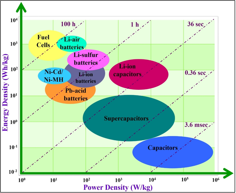
Efforts to improve energy storage capability, power, and energy density continue as aerospace systems expand beyond Earth environments. A way for researchers to characterize energy storage is using a Ragone plot to show the non-linear relationship between the energy that can be extracted from the storage and the discharge power (27).For energy storage systems, the overall hierarchy is fundamentally the same since the last decade in terms of tradeoffs. Figure 3.6 is by researchers from the Chemical Society of Japan to illustrate the advancements in Li-based technology, supercapacitors, and solid-state battery formats.
Ongoing research of energy storage systems indicate the successors of Li-ion cells include Li-metal, Li-Sulfur, silicon-rich anodes, high-voltage cathodes, solid-state configurations, and hybrid systems of a rechargeable battery and capacitor. While these methods have promising energy densities, they often involve trade-offs in cycle life and stability (28).
As demand grows for higher energy output in smaller volumes, several challenges remain for long-term use in space. While system-level energy density in Li-ion batteries is reduced by components like battery management systems (BMS) and thermal controls, research continues to push the performance boundaries.
3.5.1 Nanomaterials
There has been sustained focus on renewable energy sources, and the accumulated research on nanomaterial development and testing shows next-generation power (and thermal) systems will incorporate nanomaterials. Fueled by the adoption of electric automotives, research using nanomaterials as a main conductive additive for energy storage is rapidly emerging. There has been tremendous development and testing of nanomaterials, and ongoing research— now showing promising laboratory results—suggests next-generation power systems will include them. A power system with integrated carbon nanotubes into Li-ion batteries can significantly increase energy density (30); and recently researchers found that twisting ropes of single-walled carbon nanotubes can significantly increase nanomechanical energy while retaining stability across a wide temperature range (31).
Graphene is being explored for space applications for its unique electrical properties that result in enhanced durability and performance. A single layer of carbon, graphene is lightweight with high electrical conductivity, flexibility, and mechanical strength, and is also impermeable to gas and liquid (32). These qualities make graphene ideal for several uses on spacecraft power and thermal management, and as a coating for spacecraft graphene can greatly enhance the heat transport in conductive materials. Researchers have high interest in understanding how to implement graphene-based batteries and supercapacitors for space applications.
The electrical properties of conducting polymer materials can improve battery performance and are being examined for next generation additives or coatings for battery systems. Conductive polymers have high structural flexibility that can accommodate the volume changes during battery cycling when the doping type and concentration are modified (33). There exists a multitude of research on the characterization of conducting polymers in various battery chemistries with advantageous potential for space operations.
Electrolytic carbon fiber materials are emerging for spacecraft as multifunctional “structural” battery systems that can bear mechanical loads while simultaneously storing energy. Being integrated into the primary structure, this novel battery system significantly reduces mass, and benefits from the electrical characteristics of carbon fiber-based electrodes. There has been extensive research that supports the increased electrochemical performance and accuracy of the computational models (34), though further development and testing of individual components is needed to implement in space.
The manufacturing of nanomaterials for aerospace applications is a complicated process. Due to the nature of nanomaterials, there are often inconsistencies during manufacturing where attributes like uniformity, purity, and size distribution of individual nanoparticles are not uniform to achieve desired properties/performances. Scaling up from lab to production requires precise control over nanoparticle morphology, alignment, and integration into large-scale structures like spacecraft bodies and satellites. Additionally, the current performance of nanomaterial technology cannot withstand radiation-induced degradation during long term spaceflight (36).
3.5.2 Supercapacitors
While traditional supercapacitors (also called ultracapacitors) have limited energy densities (~7 Wh/kg), recent advancements leveraging nanostructured carbon materials have achieved 60 Wh/kg (51). The very high power densities (10–100 kW/kg) of supercapacitors are ideal for space operations requiring rapid power transients (i.e., ADCS control, propulsion, or radar systems). Their fast charge/discharge capabilities, exceptional cycle life (over 1 million cycles), and broad operational temperature range make them well-suited for spacecraft. While early ESA studies such as the 2010 “High Power Battery Supercapacitor Study” (54) and the 2020 qualification of the Nesscap 10F component laid the groundwork, recent ESA-backed research (e.g., Swistor SA, 2024) has demonstrated next-generation supercapacitors with enhanced energy density, thermal resilience, and environmental sustainability.
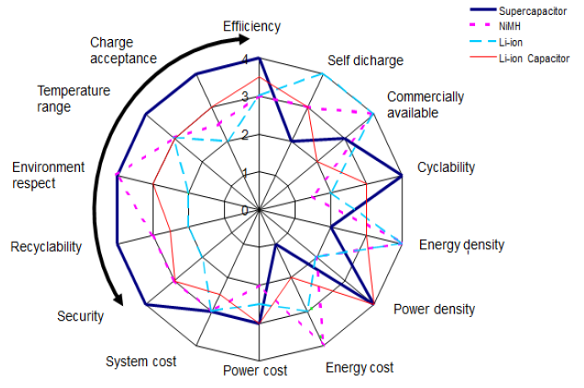
Although not likely to replace Li-ion batteries completely, supercapacitors could drastically minimize the need for a battery and help reduce weight while improving performance in some applications. Figure 3.9 shows a comparison chart (55), and Table 3-6 lists differences in Li-ion batteries and supercapacitors (56). A hybrid energy storage system combining a Li-ion battery and supercapacitor has been a niche area of research for over a decade. They provide a middle ground between power density and energy density but suffer from limited life-cycles. Some lithium-ion capacitors have demonstrated specific energies up to ~200 Wh/kg but are limited by a maximum specific power of <350 Wh/kg (58).
| Table 3-6: Battery-vs-Supercapacitor Specifications | ||
|---|---|---|
| Feature | Li-Ion Battery | Supercapacitor |
| Gravimetric energy (Wh/kg) | 150 – 265+ | 5 – 20 |
| Volumetric energy (Wh L-1) | 220 – 450 | 4 – 14 |
| Power density (W kg-1) | 1,500 | 3,000 – 40,000 |
| Voltage of a cell (V) | 3.6 | 2.7 – 3 |
| ESR (mΩ) | 500 | 40 – 300 |
| Efficiency (%) | 80 – 95 | >98 |
| Cyclability (nb charges) | 2,000 – 70,000 | 500,000 – 20, 000,000 |
| Life (years) | 5 – 10 | 10 – 15 |
| Self-discharge (% per month) | 2 | 40 – 50 (descending) |
| Charge temperature (°C) | 0 to 45 | -40 to 65 |
| Discharge temperature | -20 to 60 | -40 to 85 |
| Deep discharge pb | yes | no |
| Overload pb | yes | no |
| Risk of explosion | yes | no |
| Charging 1 cell | complex | easy |
| Charging cells in series | complex | complex |
| Voltage on discharge | stable | decreasing |
| cost ($) per kW h | 235 – 1,179 | 11,792 |
3.5.3 Solid-State Batteries
The flammable nature of the liquid electrolyte in conventional Li-ion configurations presents an inherent risk of combustion, particularly in the event of physical damage or thermal runaway caused by overcharging. To mitigate these risks, spacecraft often require additional weight for thermal management and protective housings, which adds parasitic weight and complexity. In contrast, solid-state batteries replace liquid electrolytes with non-flammable solid electrolytes that maintain high ionic conductivity (42). These electrolytes, usually polymer-based, inorganic, and polymer-inorganic composites, offer several benefits over traditional Li-based batteries like improved safety, high energy and power density, greater thermal stability, mechanical flexibility, and long-life cycle. For deep-space applications, solid-state batteries are being engineered for radiation tolerance, vacuum compatibility, and mechanical robustness, often requiring trade-offs in electrolyte composition or packaging design (42).
Researchers across the globe have developed various configurations like all-solid-state lithium-ion batteries (ASSLBs), which replace both electrolyte and separator with a solid material. Solid-state lithium–sulfur batteries (SSLSBs) combines a lithium metal anode with a sulfur cathode and solid electrolyte to achieve theoretical energy densities over 500 Wh/kg (43); and lithium metal solid-state batteries with lithium metal as the anode for higher energy density, though this requires careful engineering to prevent dendrite formation (45). Researchers at JAXA successfully characterized ASSLB on the ISS for 434 days that confirms their potential application to space exploration (44).
Despite the advantages of solid-state batteries, several challenges that must be addressed before they can be reliably adopted in space. A primary concern is thermal management of the solid electrolyte material under extreme conditions, which significantly impacts their electrochemical performance. Solid electrolytes typically have lower thermal conductivity, making it difficult to dissipate heat effectively. This can lead to localized hotspots, which degrade battery materials over time. Additionally, the mismatch in thermal expansion coefficients of the various materials in a solid-state-battery introduces mechanical stress during temperature fluctuations potentially compromising structural integrity and performance (46). See Table 3-7 for examples of solid-state batteries.
| Table 3-7: Solid-State Batteries | |||
|---|---|---|---|
| Manufacturer | Product | Wh/kg | Wh/L |
| Solid Power | Silicon EV Cell | 390 | 930 |
| Solid Power | Lithium Metal | 440 | 930 |
| Solid Power | Conversion Reaction Cell | 560 | 785 |
| QuantumScape | LFP (projected) | 230 | 600 |
| QuantumScape | NMC (projected) | 300 | 1000 |
3.5.4 Energy Storage Systems
A single energy storage unit that can store excess energy generated during periods of high production and make it available during low production intervals is highly advantageous for both terrestrial and space applications. A hybrid energy storage system (HESS) combines the high energy density of batteries (usually Li-ion-based) with the high-power density and longer life cycle of supercapacitors. The batteries provide primary energy storage, while the supercapacitor handles peak power demands. This reduces stress on the battery, prevents degradation, and improves power dissipation. Researchers from California State University, Northridge in collaboration with JPL developed a passive HESS that was successfully operated on nanosatellite CSUNSat-1 in 2017 (47). While the only HESS technology in space, the advancements in HESS technology have increased though mainly due to renewable energy sources for terrestrial applications.
Designing a HESS for a space mission presents several technical challenges, including the need to improve energy density and efficiency of storage technologies, ensure compatibility between different power systems within a single unit, and manage high development cost (48). Critical considerations include maintaining voltage compatibility and precisely controlling the charge and discharge rate of the storage components to ensure system stability and performance (49). For more detailed insights into ongoing development, interested readers are highly encouraged to consult references (51)(52).
3.6 State-of-the-Art – Power Management and Distribution
Power management and distribution (PMAD) systems—also called power conditioning and distribution units (PDCUs)— regulate and distribute electricity to spacecraft subsystems and instruments. PMAD systems are typically comprised of converters, power transfer circuitry, and fault management functions. These systems are most often customized per mission with specific power requirements to efficiently manage and distribute electrical power. From generation through consumption, the PMAD unit delivers energy from energy sources—such as solar arrays or batteries— and detects and isolates faults, protecting downstream components from transient disturbances. Other core functions of the PMAD system are voltage regulation from the bus to the different voltage requirements of the subsystems; load switching that enables/disables the power to subsystems; and interfaces with the onboard computer to monitor temperature and current.
An optimal PMAD architecture is fault-tolerant with high reliability and a small footprint. Traditional small spacecraft EPS operate with a main battery bus voltage of 8.2 V and provide regulated outputs at 5.0 V and 3.3 V to various subsystems via the PMAD system. However, modern small spacecraft with high-power payloads (i.e., inter-satellite cross laser links, multispectral imaging, synthetic aperture radars, IoT constellations) have more than doubled the power requirement the PMAD must handle (53). Newer converter designs with Gallium Nitride (GaN)-based power converters can support a broader range of voltages, including 12V, 28V, and 50V (54).
To further support high-performance or deep space SmallSat missions, PMAD systems are designed with enhanced shielding and fault-tolerant architectures. Aided by the rise of modular and software defined architectures, scalable PMAD designs can provide commonality across all the components in a spacecraft.
Modular Architecture
Modular architecture is ideal as it reduces mass and increases power. Shifting from fixed EPS units to flexible, mission customizable PMAD systems drives more powerful and scalable SmallSat capabilities.
Within NASA’s Mars Campaign Office, the Advanced Modular Power Systems (AMPS) project—led by NASA Glenn Research Center—is developing a standardized space power system architecture at the electronics‑module level. This includes defining the form and function of electronic modules (circuit cards) and modular electronic units that make up power system components. The goals include reducing power‑system maintenance operations, improving system availability by minimizing outage and restoration times, and decreasing the number of unique spare parts. Together, these advances help lower sparing mass and volume requirements, which are essential for enabling sustainable exploration missions (55).
3.6.1 PMAD Selection Considerations
Key considerations in determining PMAD device selection often include conversion efficiency, input/output voltage range, output power capabilities, and size, weight, and power (SWaP). These metrics are critical to consider for good SmallSat PMAD designs, but it is important to note that PMAD devices should be selected to match the specific application of the SmallSat mission. SmallSat missions are often short and more flexible in terms of risk management than larger satellites, and therefore lend themselves to greater flexibility in design choices. One must leverage the benefits and risks to the mission at hand when choosing COTS PMAD systems, which may include the following:
- COTS PMAD may require less intensive integration and testing but may have drawbacks to be addressed in a custom PMAD build
- Unnecessary features and peripherals (e.g., excess switching, fusing, current capability) can greatly increase SWaP metrics on a SmallSat
- Variability in designs of COTS PMAD devices means that important features and protections are not available in all devices (MPPT, Dead-bus protections, redundancy mechanisms, etc.)
Due to the variability of COTS PMAD options, many choice considerations, from internal power management topologies/materials to telemetry and protection options, are either included or omitted from products depending on the manufacturer. Internal power regulation topologies have traditionally been silicon-based, but relatively recent research into the performance improvements of Gallium Nitride (GaN) topologies has increased the number of GaN-based PMAD options in the consumer market with the following benefits over their silicon counterparts:
- Ability to achieve high switching rates and lower switching losses, allowing for the downsizing of inductors and capacitors, and improving SWaP metrics
- Lack of gate oxide layer in GaN-based field-effect transistors yields improvements in overall efficiency
It must also be noted that GaN-based PMAD options are not to be considered as drop-in replacements for silicon-based PMAD options. Despite the number of performance improvements, GaN architectures come with a variety of drawbacks including high complexity of control circuitry and lack of flight heritage.
Additional considerations when selecting a PMAD device for small spacecraft include radiation tolerance, especially for missions beyond LEO, and telemetry capabilities for real-time health monitoring. As mission complexity increases, modular PMAD architectures are gaining popularity for their scalability and ease of integration. Furthermore, thermal performance remains a critical factor, particularly in high-density CubeSat designs where heat dissipation is limited.
Table 3-8 lists PMAD system manufacturers; it should be noted that this list is not exhaustive and all information is taken from company websites and datasheets. Manufacturers tend to provide a variety of PMAD devices for inclusion in small spacecraft missions. In looking at the table below, one must note that there is no single COTS PMAD solution that can fit all needs of a mission at hand. In appealing to a broad range of applications, most COTS PMAD devices make sacrifices that can impact important metrics for SmallSats, including SWaP as well as the efficiency and quality of the power being managed. In choosing to use COTS PMAD devices, designers and system architects should be aware of, and try to minimize, unnecessary features not beneficial to the mission.
| Table 3-8: Power Management and Distribution System Products | |||||||
|---|---|---|---|---|---|---|---|
| Company | Product | Mass (kg) | Volume (cm3) | Peak Power Output (W) | Input Voltages (VDC) | Output Voltages (VDC) | Max Efficiency (%) |
| 2NDSpace Italy | SOLO-EPS 4 | 0.465 | 428 | 104 | 16.8 | 3.3V; 5V; 12V; 16.8V | 92 |
| SOLO-EPS 8 | 0.67 | 606 | 160 | 16.8 | 3.3, 5, 12, 16.8 | 92 | |
| AAC Clyde Space Sweden | Starbuck Micro | 2.45 | 3968 | 80.4 | 28 | 28 / 5 | 97 |
| Starbuck Mini | 5.9 | 13133 | 1200 | * | 22-34/5/8/12/15 | * | |
| Starbuck Nano | 0.086 | 140 | * | * | 3.3/5/12 | * | |
| Aerospacelab Belgium | PCDU | 1.635 | 1715.5 | 960 | [0; 65] V | 5V [4.75, 5.25] V 12V [11.4, 12.6] | >97 |
| Argotec Italy | PCDU VOLTA | 0.97 | 600 | 100 | 18-22 | 1x 3.3 V, 1x 5 V, and 2x 12 V | 75 |
| PCDU ZEUS | 0.56 | 532 | 220 (Solar + battery power) | 8.5-24 V | 3.3 V; 5 V; 12 V; 28 V (unregulated) | 85 | |
| PCDU PHOENIX | 1.5 | 1400 | 250 | 31-55 V | 3.3 V; 5 V; 12 V; 28 V (unregulated) | 85 | |
| Berlin Space Technologies Germany | PCU-110 | 1.08 | 1190 | 180 | standard: 20-28 optional: 12, 15, 18 | standard: 2x 12, 12x 5, 5x 3.8 optional: 1.8 – 28 | * |
| Bradford Space Luxembourg | SuperNova modular PCDU | 2.9 | 3045 | 1500 | 22 – 34 | 3.3/5/12/unreg. batt | 95 |
| C3S Electronics Development LLC Budapest | EPS1000 | 0.811 | 748.5 | 70 | 6-25V SA | 9.9-12.3V, 3.3V, 5.1V | 90 |
| EPS2000 | 5.8 | 7000 | 2kW | 6V-25V or 30-70V (SA) | 28V unregulated | 97 | |
| DHV Technologies Spain | MicroEPS | 1.250~2.850* | 392~1045* | 592 in eclipse / 693 in sunlight | 9-40 | 3.3/5/12 Batt | >90 |
| NanoEPS | 0.175~0.540* | 283~600* | 59 in eclipse / 124 in sunlight | 9-28 (X/Y) / 3-18 (Z) | 3.3/5/12 Batt | >93 | |
| PicoEPS | 0.110~0.315* | 140~197* | 29 in eclipse / 74 in sunlight | 3-18 | 3.3/5/12 Batt | >93 | |
| Battery Module | ~3.1 | ~2200 | ~930 | 24 | 33.6 | – | |
| PCDU | 3.4~3.9 | 4704~5720 | ~900 | 20~70 | 3.3/5/12 Batt | >90 | |
| Dragonfly Aerospace South Africa | EPS-LP-1k5 (PCDU) | 3.3 (Cfg: EPS-LP-12333) | 5650 (Cfg: EPS-LP-12333) | 1500 | 29.7 (22 to 36) | Battery Bus: 29.7 Regulated: 12 / 5 | 98 |
| EPS-LP-1k5 + HPIU-28V | 7 | 10170 | 4200 | 29.7 (22 to 36) | Battery Bus: 29.7 Regulated: 12 / 5 | 95 | |
| EPS-LP-1k5 + HPIU-48V | 10 | 11187 | 7200 | 49.5 (42 to 60) | Regulated: 28 / 12 / 5 Battery Bus: 49.5 | 92 | |
| Ecarver GmBH Germany | PCU-SB7 | 1.5 | 1800 | 250 | 0-24 | 0-24 | 85 |
| EmxysSpain | ODALISS PDCU | 0.36 | 416.3 | 36 | 14-36 | Main 7.6V unreg/ Redundant 7.7V unreg/ Regulated 3.3V/ Regulated 5.0V | 95 |
| EnduroSat Bulgaria | EPS II | 1.28 | 742 | 250 | 10-36 | 3.3/5/6-12/Batt | 89 |
| CubeSat EPS | 1-6 | 860-4000 | 500 | 0-45 | 3.3/5/12/Batt | 87 | |
| EPS IV | 4.5 | 7208 | 7200 | 0 -70 | 12/28/Batt | 90 | |
| GomSpace Denmark | P31U | 0.1 | 127 | 30 | 0-8 | 3.3/5 | 96 |
| P60 | ** | ** | 100 | 16/32 V | 3.3/5/8/12/18/ 24 | – | |
| P80 | 360-610g ¥ | 350–586 | 300 | 0-25 | 3.3/5/12/18V & Vbat | – | |
| GUMUSH AeroSpace Istanbul | n-ART EPS | 0.098 | 160 | 100 | 4.5-30 | 3.3/5/8-36/Batt | 94 |
| Ibeos USA | 150 W CubeSat EPS | 0.14 | 124 | 150 | 18-42 | 3.3/5/12/Unreg Batt | 95 |
| Ibeos USA | 200 W CubeSat EPS | 0.14 | 124 | 200 | 12-34 | 3.3/5/12/Unreg Batt | 96 |
| Modular EPS | Starting at <1 | Starting at 1150 | 500 – 2,000 | 12-26 | 5/12/Unreg Batt | 98 | |
| ISISPACE The Netherlands | ICEPS2 Type A | 0.184¥ | 223 | 39.2 | — | 3.3/5/Unreg | 96 |
| ICEPS2 Type B | 0.31 | 275 | 78.4 | — | 3.3/5/Unreg | 95 | |
| ICEPS2 Type C | 0.36 | 317 | 78.4 | — | 3.3/5/28.2/Unreg | 95 | |
| Nanoavionics Lithuania | CubeSat EPS (EPS 1.0) | * | * | 175 | 2.6-12 | 3.3 / 5 / 3-12 | 96 |
| NPC SPACEMIND Italy | GEMINI | 0.3 | 215 | 200 | 10 to 24 | 1 or 2 X 3.3 1 or 2X 5.0 2X 12V Reg up to 24V | 88 |
| Pumpkin Space Systems USA | EPSM 1 | 0.3 | 180 | 300 | 4-32 | 3.3-28 | 99 |
| AMPS | 1.3 | 360 | 1200 | 5-32 | — | 99 | |
| SatRev S.A Poland | EPS 3S1P | 0.483 | 397 | 80 W | 4.5 – 20 | Unreg 9.6-12.6 | > 95 |
| EPS 3S2P | 0.751 | 630 | 160 W | 4.5 – 20 | Unreg 9.6-12.6 | > 95 | |
| EPS 3S3P | 0.989 | 865 | 240 W | 4.5 – 20 | Unreg 9.6-12.6 | > 95 | |
| SkyLabs Slovenia | SKY-NANOeps-PCDU-23c-5d | 0.2 | 216.125 | 72 | 10V Unreg | 3.3, 5, 12, 10 Unreg | 99 |
| Spacemanic Czech Republic | Amun 1U | 0.2 | 175 | 20 | ~ 2.5 – 5.5 | 3.3 / 5 / Batt | ~ 90 |
| Space Inventor Denmark | PDU-3V3 | 0.104 | 69 | 80W | 12 to 33.6V | 3.3V | 95 |
| PDU-5V | 0.104 | 69 | 120W | 12V to 33.6V | 5.0V | 95 | |
| PDU-12V | 0.104 | 69 | 290 W | 14V to 33.6V | 12V | 95 | |
| PDU-VBAT | 0.104 | 69 | 1000W | 12V to 33.6V | 12V to 33.6V | 99 | |
| * Available with inquiry to manufacturer ** Configuration dependent † Standard Configuration ⁑ Optional radiation shielding case ¥Flexible stacking options Standard options | |||||||
3.7 On the Horizon – Power Management and Distribution
Power management and distribution have been steadily improving each year due to improvements in technology and the different investigative approaches to maximizing the potential of PMAD systems. This includes modular architectures, wireless telemetry, and power transmission options. However, as multi-satellite missions— such as constellations or swarms— become more common, reliability concerns of PMAD systems are shifted from a single spacecraft-level redundancy to constellation-level redundancy.
Wireless Power Transfer and Telemetry
In the commercial world, the technology already exists for wireless sensing and power transmission from the order of microwatts, all the way up to kilowatts. In the realm of SmallSats, wireless power transfer/detection would be useful as redundant options in dusty environments where physical connectors can be contaminated, or in situations where hardware needs to be swapped around and powered (battery swaps). While wireless power transfer/detection is highly inefficient when compared to conventional means, research and development in this technology for use in space applications has a lot of potential to increase the reliability and robustness of SmallSat power management and distribution.
3.8 Summary
Driven by weight and mostly size limitations, small spacecraft are using advanced power generation and storage technology such as >34% efficient solar cells and lithium-ion batteries. The higher risk tolerance of the small spacecraft community has allowed both the early adoption of technologies like flat lithium-polymer cells, as well as COTS products not specifically designed for spaceflight. This can dramatically reduce cost and increase mission-design flexibility. In this way, power subsystems are benefiting from the current trend of miniaturization in the commercial electronics market, as well as from improvements in photovoltaic and battery technology.
Despite these developments, the small spacecraft community has been unable to use other, more complex technologies. This is largely because the small spacecraft market is not yet large enough to encourage the research and development of technologies like miniaturized nuclear energy sources. Small spacecraft power subsystems would also benefit from greater availability of flexible, standardized power management and distribution systems so that every mission need not be designed from scratch. In short, today’s power systems engineers are eagerly adopting certain innovative Earth-based technology (like lithium polymer batteries) while, at the same time, patiently waiting for important heritage space technology (like fuel cells) to be adapted and miniaturized. Despite the physical limitations and technical challenges these power generation technologies have, most small nanosatellites in the foreseeable future will still likely carry batteries to support transient loads.
For feedback solicitation, please email: arc-sst-soa@mail.nasa.gov. Please include a business email so someone may contact you further.
References
- E. Peretz et al. “The Importance of Solar Power Technology Adaptations to Space Exploration”, 2024
- Sectrolab. “XTE-HF (High Fluence): Space Qualified Triple Junction Solar Cell,” [Online] Accessed February 16, 2026. Available at: https://www.spectrolab.com/photovoltaics/XTE-HF%20Data%20Sheet%20_12.23.19.pdf
- Rocket Lab. “z4j+ Space Solar Cell,” [Online] Accessed February 16, 2026. Available at: https://rocketlabcorp.com/assets/Uploads/RL-SolAero-Data-Sheet-Z4J+-v8.pdf
- M. Alia-Novobilski. “Advanced Multi-junction Solar Cells Deliver High Efficiency, Reduced Costs for Space.” January 4, 2018. [Online] Accessed February 16, 2026. Available at: https://phys.org/news/2018-01-advanced-multi-junction-solar-cells-high.html#jCp
- National Laboratory of the Rockies. “Hybrid Tandem Solar Cells,” December 6, 2025 [Online] Accessed February 16, 2026. Available at: https://www.nrel.gov/pv/hybrid-tandem-solar-cells
- Fraunhofer Institute for Solar Energy Systems ISE. “Fraunhofer ISE Develops the World’s Most Efficient Solar Cell with 47.6 Percent Efficiency,” May 30, 2022. [Online] Accessed February 16, 2026. Available at: https://www.pv-magazine.com/2018/04/04/fraunhofer-ise-announces-33-efficiency-for-multi-junction-solar-cell/
- “Indoor photovoltaics with over 40 percent efficiency developed,” July 16, 2025. [Online] Accessed July 16, 2021. Available at: https://www.ise.fraunhofer.de/en/press-media/news/2025/indoor-photovoltaics-with-over-40-percent-efficiency-developed.html
- National Laboratory of the Rockies. “Photovoltaic Applications,” January 12, 2026 [Online] Accessed February 16, 2026. Available at: https://www.nlr.gov/pv/applications
- National Lab Discovery Series: Dynamic Hydride Vapor Phase Epitaxy – High-Performance III-V,” NREL, September 29, 2025
- T. CJ Yang, P. Fiala, Q. Jeangros, and C. Ballif, “High-Bandgap Perovskite Materials for Multijunction Solar Cells,” Joule 2, 1421–1436, August 15, 2018
- M.A. Green, E.D. Dunlop, M. Yoshita, et al. Solar cell efficiency tables (Version 64). Prog Photovolt Res Appl. 2024;32(7):425-441. doi:10.1002/pip.3831
- Ricoh. “Ricoh perovskite solar cells installed on Japan Aerospace Exploration Agency cargo transfer spacecraft1 HTV-X1,” Press release. October 27, 2025 [Online] Accessed February 16, 2026. Available at: https://www.ricoh.com/release/2025/1027_1
- J. Toon. “Space Station Testing Will Evaluate Photovoltaic Materials,” June 24, 2025. Georgia Tech Research Institute. [Online] Accessed February 16, 2026. Available at: https://www.gtri.gatech.edu/newsroom/space-station-testing-will-evaluate-photovoltaic-materials,
- P. A. Makode, S. P. Muduli, P. Kale. “A perspective of GaAs//Si tandem photovoltaic cell: Architecture, fabrication, and performance,” February 20, 2025. Materials Research Bulletin (190), https://doi.org/10.1016/j.materresbull.2025.113504
- Helmholtz-Zentrum Berlin. “Photovoltaics: Generating electricity from sunlight,” Division Solar Energy [Online] Accessed February 16, 2026. Available at: https://www.helmholtz-berlin.de/forschung/unsere-forschung/photovoltaik/index_en.html
- National Research Council of Science and Technology. “Lighter and More Flexible Solar Cells Achieve World’s Highest Efficiency,” newswise. April 9, 2025. [Online] Accessed February 16, 2026. Available at: https://www.newswise.com/articles/lighter-and-more-flexible-solar-cells-achieve-world-s-highest-efficiency
- Uppsala University. “CIGS-Based Thin Film Solar Cells,” Department of Materials Science and Engineering: Research: Solar Cell Technology. February 12, 2026. [Online] Accessed February 16, 2026. Available at: https://www.uu.se/en/department/materials-science-and-engineering/research/divisions/solar-cell-technology/cigs-based-thin-film-solar-cells
- Julio C. Carrillo-Sendejas, José-Luis Maldonado; Progress in organic solar cells: Materials, challenges, and novel strategies for niche applications. APL Energy 1 June 2025; 3 (2): 021501. https://doi.org/10.1063/5.0267160
- R. Kennedy. “Organic solar cells for space demonstrate radiation resistance, self-healing,” January 10, 2025, [Online] Accessed February 16, 2026, Available at: https://pv-magazine-usa.com/2025/01/10/organic-solar-cells-for-space-demonstrate-radiation-resistance-self-healing/
- A. Shahzad, H.J Jiang, K.F Aguey-Zinsou. “Unitized regenerative fuel cells: Fundamental challenges and advancements,” Renewable and Sustainable Energy Reviews, Volume 215, 2025, 115631, ISSN 1364-0321, https://doi.org/10.1016/j.rser.2025.115631
- B.V Kumar, K. Kentaro, and N.C Orger. “A review on design challenges and future opportunities of battery management system for low earth orbit nanosatellites.” Discov Appl Sci 8, 470 (2026). https://doi.org/10.1007/s42452-026-08369-8
- H. Fan. “Exploring the Relationship Between Lithium-ion Battery Mass and Energy Density,” September 17, 2025, [Online] Accessed February 16, 2026, Available at: https://www.large-battery.com/blog/lithium-ion-battery-weight-and-density-explained-guide/
- Amprius Technologies. “AALTO Zephyr Achieves World-Record 67-Day Flight Powered by Amprius Ultra-High-Energy Batteries,” Announcements. [Online] Accessed February 16, 2026, Available at: https://amprius.com/aalto-zephyr-achieves-world-record-67-day-flight-powered-by-amprius-ultra-high-energy-batteries/
- K. Sharma and A. Santasalo-Aarnio, “Energy storage systems for space applications,” Journal of Energy Storage, Volume 128, 2025, 117131, ISSN 2352-152X, https://doi.org/10.1016/j.est.2025.117131.
- P. Casado, J.M. Blanes, A. Garrigós, D. Marroquí, C. Torres, “Evaluation of commercial Li-Ion 18650 battery cells for deep space applications,” Journal of Power Sources, Volume 638, 2025, 236552, ISSN 0378-7753, https://doi.org/10.1016/j.jpowsour.2025.236552.
- D. Petrushenko, P. Coman, et al. “Scale-Up of PPR Battery Design for 21700 Format Cells,” NASA Aerospace Battery Workshop, November 14-16, 2023.
- I. Beyers, A. Bensmann, R. Hanke-Rauschenbach, “Ragone plots revisited: A review of methodology and application across energy storage technologies,” Journal of Energy Storage, Volume 73, Part D, 2023, 109097, ISSN 2352-152X, https://doi.org/10.1016/j.est.2023.109097.
- A. Rose, “Unlocking the potential of lithium-sulfur batteries,” Argonne National Laboratory Press release, January 13, 2025, [Online] Accessed February 16, 2026, Available at: https://www.anl.gov/article/unlocking-the-potential-of-lithiumsulfur-batteries
- A. Mateen, M. Suneetha, S. S. Ahmad Shah, M. Usman, T. Ahmad, I. Hussain, S. Khan, M. A. Assiri, A. M. Hassan, M. S. Javed, S. S. Han, R. H. Althomali, M. M. Rahman, Chem. Rec. 2024, 24, e202300235. https://doi.org/10.1002/tcr.202300235.
- R. Raffaelle. “Demonstration of a Nano-Enabled Space.” 2018. [Online] Available at: https://ntrs.nasa.gov/archive/nasa/casi.ntrs.nasa.gov/20170011060.pdf
- S. Utsumi, S.K. Ujjain, S. Takahashi, et al. “Giant nanomechanical energy storage capacity in twisted single-walled carbon nanotube ropes,” National Nanotechnology 19, 1007–1015 (2024). https://doi.org/10.1038/s41565-024-01645-x
- P. Kumar Kanti, P. Kumar H G, V. Wanatasanappan, A. Kumar, M. B. Regasa, “Graphene’s Frontier in aerospace: current applications, challenges, and future directions for space engineering,” Nanoscale Advances, Volume 7, Issue 12, 2025, Pages 3603-3618, ISSN 2516-0230, https://doi.org/10.1039/d4na00934g.
- K. B. M. Ismail, M. A. Kumar, S. Mahalingam, R. Jayavel, M. Arivanandhan, J. Kim, “Conducting polymer based electrodes in metal-ion batteries: A state-of-the-art review,” Renewable and Sustainable Energy Reviews, Volume 222, 2025, 115982, ISSN 1364-0321, https://doi.org/10.1016/j.rser.2025.115982.
- R.L. Karkkainen. “Development of Lightweight CubeSat with Multi-Functional Structural Battery Systems.” 2018. [Online] Available at: https://ntrs.nasa.gov/archive/nasa/casi.ntrs.nasa.gov/20170011078.pdf
- C. Larsson, F. Larsson, J. Xu, et al. Electro-chemo-mechanical modelling of structural battery composite full cells. npj Computer Materials 11, 141 (2025). https://doi.org/10.1038/s41524-025-01646-x
- E. Martinez, “Nanomaterials for Space Exploration: Challenges and Opportunities,” American Journal of Nano Science and Technology. VOL 06 ISSUE 03 2025
- V. Manzi-Orezzoli and C. Moldovan, “High Energy Density Supercapacitors for Space Applications,” April 28, 2025, [Online] Accessed February 16, 2026, Available at: https://passive-components.eu/high-energy-density-supercapacitors-for-space-applications/
- B. Faure, L. Cosqueric, and V. Gineste. “Evaluation and Qualification of Commercial Off-The-Shelf Supercapacitors for Space.” 2nd Space Passive Component Days (SPCD) International Symposium. Noordwijk, The Netherlands: s.n., 2016.
- SupercapTech. SupercapTech. May 21, 2016. [Online] Available at: https://www.supercaptech.com/battery-vs-supercapacitor
- POWERBOX. “The Silent Power of Supercapacitors.” White paper 017. 2019.
- M. Soltani and S. H. Beheshti. “A comprehensive review of lithium -ion capacitor: development, modelling, thermal management and applications,” Journal of Energy Storage, Volume 34, 2021.
- Y. Gupta, B. Shao, and F. Han, “Solid State Batteries Volume 1: Emerging Materials and Applications ACS Symposium Series; American Chemical Society: Washington, DC, 2022.
- Y.Lin, L. G.Somervill, R.Rashid, R. I.Ledesma, J. H.Kang, A. R.Kavanagh, J. S.Packard, C. H.Scrudder, A. L.Durgin, V. I.Yamakov, J.Su, D. A.Dornbusch, R. P.Viggiano, J. W.Connell, Toward 500 Wh Kg−1 in Specific Energy with Ultrahigh Areal Capacity All-Solid-State Lithium–Sulfur Batteries. Small2025, 21, 2409536. https://doi.org/10.1002/smll.202409536
- Miyazawa, Yu, Takanobu Shimada, Tetsuhito Fuse, Shuhei Shimada, Sousuke Nishiura, Hidetake Okamoto, Tetsuya Okawa, Takeshi Hoshino, Osamu Kawasaki, and Hitoshi Naito. 2025. “Space Demonstration of All-Solid-State Lithium-Ion Batteries Aboard the International Space Station” Aerospace 12, no. 6: 514. https://doi.org/10.3390/aerospace12060514.\
- Liu, H., Chen, Y., Chien, PH. et al. Dendrite formation in solid-state batteries arising from lithium plating and electrolyte reduction. Nat. Mater. 24, 581–588 (2025). https://doi.org/10.1038/s41563-024-02094-6
- F.A. Sima, A. Ghafari, and S. Akbari, “Enhancing Solid-State Battery Performance through Advanced Thermal Management Techniques,” NanoScience Technology, Volume 14 (2024), pp: 1-19.
- K. B. Chin et al., “Flight Demonstration of a Hybrid Battery/Supercapacitor Energy Storage System in an Earth Orbiting CubeSat,” in IEEE Aerospace and Electronic Systems Magazine, vol. 36, no. 5, pp. 24-36, 1 May 2021, doi: 10.1109/MAES.2021.3052309.
- Adeyinka, A.M., Esan, O.C., Ijaola, A.O. et al. Advancements in hybrid energy storage systems for enhancing renewable energy-to-grid integration. Sustainable Energy res. 11, 26 (2024). https://doi.org/10.1186/s40807-024-00120-4.
- R. Bugga, C. Krause, K. Billings, J.P Ruiz, et al. “NASA Battery Workshop.” November 19, 2019. Accessed May 16, 2020. [Online] Available at: https://www.nasa.gov/sites/default/files/atoms/files/3-nasa_battery_workshop_nov_2019_high_power_li-ion_cells_final.pdf
- S Marín-Coca, E Roibás-Millán, S Pindado, M A de Miguel and H Valente, “Hybrid energy storage systems for high power spacecraft missions,” Published under license by IOP Publishing Ltd, Journal of Physics: Conference Series, Volume 2716, 012097, DOI 10.1088/1742-6596/2716/1/012097
- Amina Daghouri, Soumia El Hani, Youssef El Hachimi, Hamza Mediouni, Enhanced hybrid energy storage system combining battery and supercapacitor to extend nanosatellite lifespan, Results in Engineering, Volume 23, 2024, 102634, ISSN 2590-1230, https://doi.org/10.1016/j.rineng.2024.102634
- https://passive-components.eu/wp-content/uploads/2025/04/ORAL_Day-2_20_Algerian-Space-Agency_Hybrid-Energy-Storage-Supercapacitors.pdf
- https://pmarketresearch.com/auto/power-conditioning-and-distribution-unit-pcdu-for-small-satellite-market/
- “Comprehensive analysis of Cubesat electrical power systems for efficient energy management,” Usama Shakoor 1 · Mohanad Alayedi2 · Ebrahim E. Elsayed, | https://doi.org/10.1007/s43937-025-00069-5