


![Request for Information – Potential [Placeholder for Prize]](https://assets.science.nasa.gov/dynamicimage/assets/science/missions/a-step/FFR_Earth_Background_20251120%20.png?w=1024)


Credits: NASA/Quincy Eggert
German Escobar works on a model aircraft wing structure that has two long sides and bars in between, which resembles a mini ladder. He sands the rough edges, uses four vices to secure it, and uses a milling machine he programmed to make precision holes.
Escobar is one of the Experimental Fabrication Shop technicians at NASA’s Armstrong Flight Research Center, Edwards California. The team made 29 different types of parts, more than 50 in total, to assemble a 10-foot unique wing model that will help calibrate fiber optic instrumentation and contribute data for a future wing model to show how the design improves fuel efficiency.
The experimental wing model has many features of the X-66 Transonic Truss-Braced Wing. The X-66 wing is braced on an aircraft using diagonal struts that also add lift and could result in significantly improved aerodynamics.

NASA Armstrong’s many capabilities enabled a start-to-finish design, fabrication, and soon testing of the 10-foot model wing. The Flight Loads Laboratory provided specifications for the model, including some of its own calculations from a 6-foot efficient wing test build at the center in Dec. 21, 2022. NASA’s Advanced Air Transportation Technology project funded the model wings.
In addition, NASA Armstrong and NASA’s Langley Research Center in Hampton, Virginia, are working on a proposal for 15-foot wing called the Structural Wing Experiment Evaluating Truss-Bracing. That wing would include ground vibration testing that would give a clearer picture of how it would react to different kinds of vibration in flight.
Andrew Holguin, a design engineer, created 3D representations of the parts and how to assemble them. Holguin divided the model wing work into subassemblies to make it easier to focus on a single set of tasks. With the design fully approved and the task orders written, Escobar began his work.
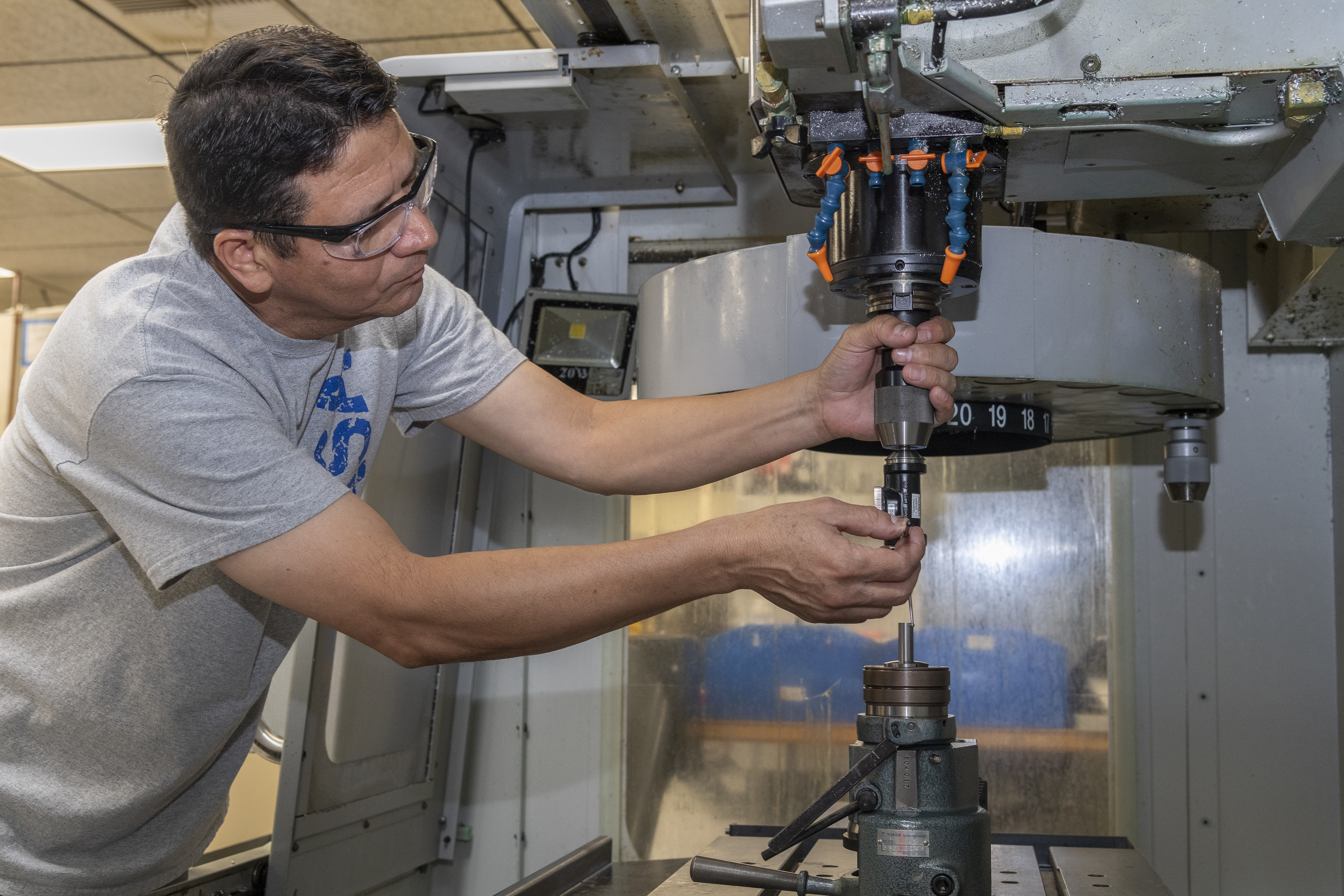
The ability to work items simultaneously is an advantage. Jose Vasquez, an engineering technician, used software to instruct a five-axis milling machine how to cut, rotate and transform a block of steel into an adapter. Water shoots at the cutting mechanism to keep everything from getting too hot.
Once the part was finished, Vasquez removed it from the machine cleaned it and used a pair of calipers, and a fine measurement tool called a micrometer, to check ensure the adaptor meets the wing model’s precise needs. If a calibration tool does not exist to check a specialized component, technicians can make one.
Elsewhere in the lab, sheet metal technician Matt Sanchez used a press brake to make bends in an aluminum sheet to form a rectangle called a wing rib. In another step he added hardware to the rib and later installed it in the model wing.
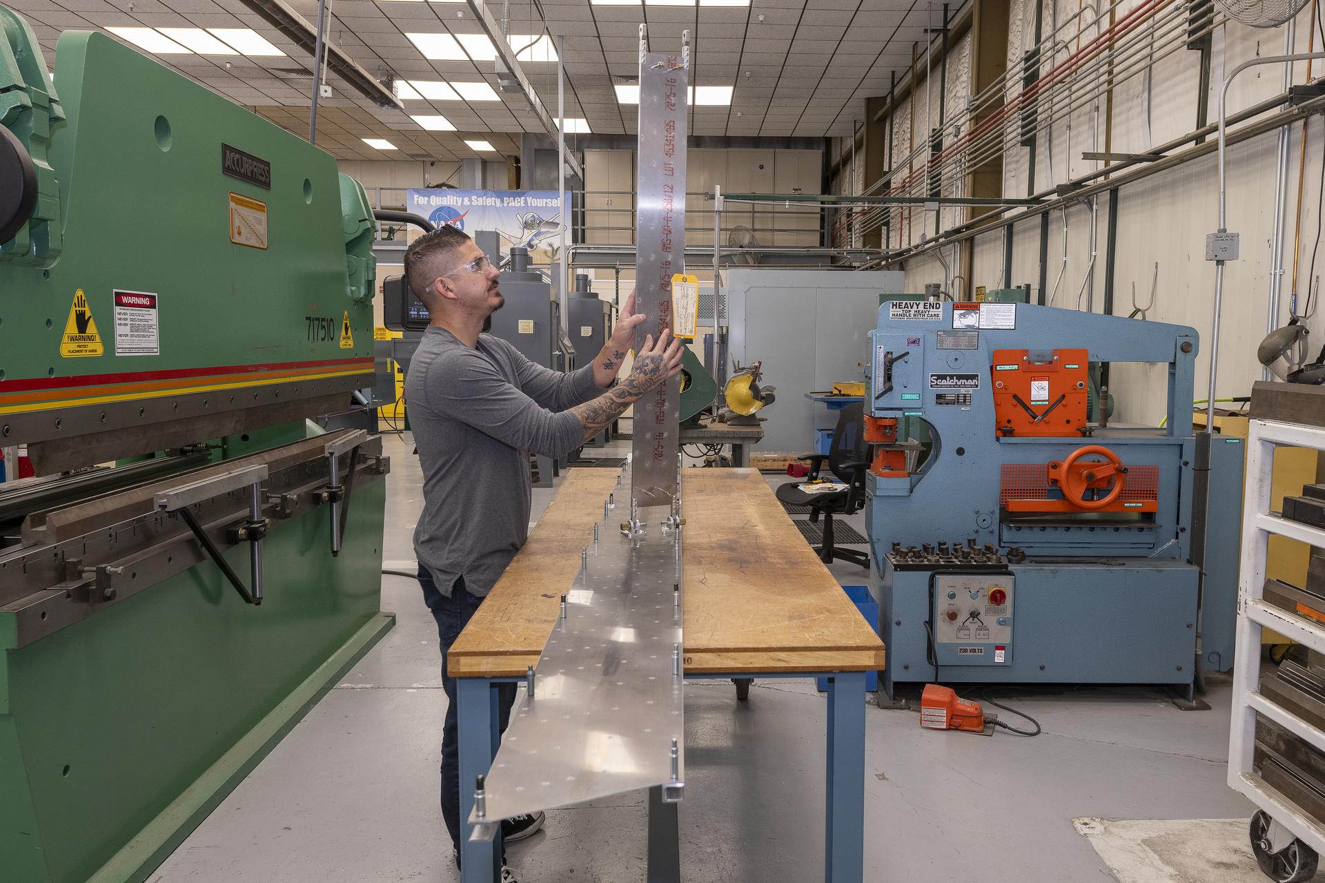
As the assembly was nearly complete, an outer wing cover was required. Sanchez set up the drawings, placed a sheet of aluminum into the water jet table and started it. Under the water the saw moved quickly to cut the strut covering down, around, and up the other side, and stopping with the complete cut. Sanchez took the piece from the table and dried it.
To wrap up this part of the work, he did a successful check of all the components called a fit check. With the wing model complete, the Flight Loads Laboratory staff continues to complete design and preparations to build a fixture for the wing tests. The fixture will join the experimental wing model, test instrumentation, and enable tests that can contribute to the next aviation innovation.
Here is a gallery of the building of the parts and the wing.