


![Request for Information – Potential [Placeholder for Prize]](https://assets.science.nasa.gov/dynamicimage/assets/science/psd/solar/2023/09/s/solarsystem_0.jpg?w=1024)


Propulsion Test Capabilities
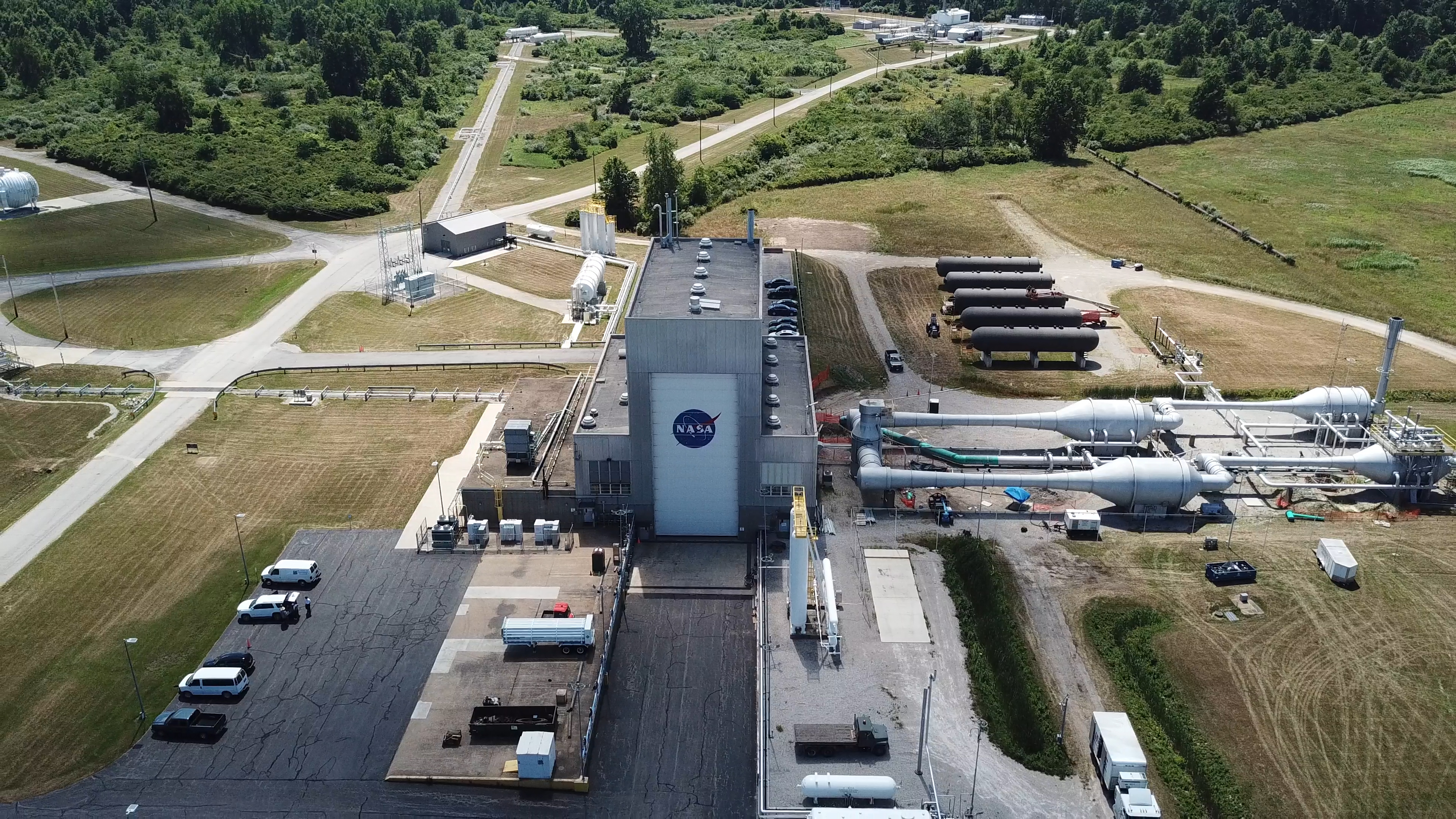
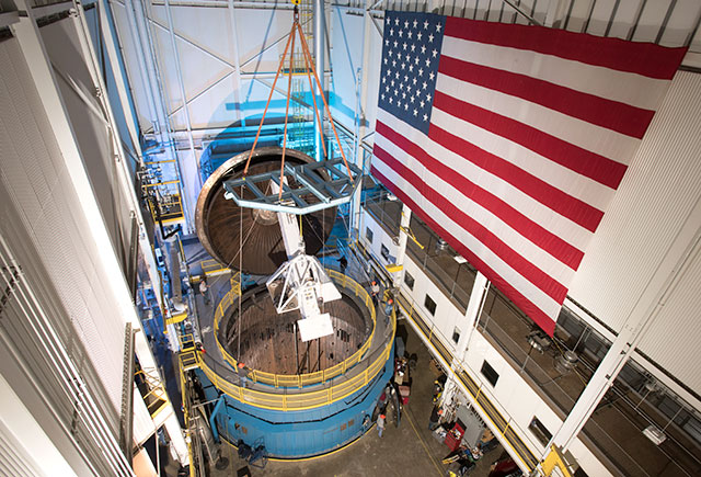
Glenn Research Center Armstrong Test Facility In-Space Propulsion (ISP) Facility
NASA’s In-Space Propulsion (ISP) Facility is the world’s only facility capable of testing full-scale upper-stage launch vehicles and rocket engines under simulated space conditions and also conducting altitude hot fire.
Overview
NASA’s In-Space Propulsion (ISP) Facility is the world’s only facility capable of testing full-scale upper-stage launch vehicles and rocket engines under simulated space conditions and also conducting altitude hot fire. The engine or vehicle can be exposed for indefinite periods to low ambient pressures, low-background temperatures, and dynamic solar heating, simulating the environment the hardware will encounter during orbital or interplanetary travel.
Vehicle engines producing up to 400,000-lb of thrust can be fired for either single or multiple burn missions, utilizing either cryogenic or storable fuels or oxidizers. Engine exhaust conditions can be controlled to simulate a launch ascent profile. In addition, conditions can be maintained before, during, and after the test firing. ISP offers a complete “test-as-you-fly” environment to thoroughly ground test flight hardware and reduce the likelihood of costly flight failures. In 1998, tests of the Boeing Delta III cryogenic upper stage were successfully conducted in the ISP facility.
During a typical test program, the test article is installed within the ISP vacuum chamber and the necessary electrical power, fuel, oxidizer, and purge gas connections are made. The low-pressure, temperature-controlled flight environment is established to thermally condition the hardware and propellants prior to engine firing.
A Programmable Logic Controller conducts all events of the engine test firing from the start of the water deluge system until the completion of the engine test firing and facility shutdown. An abort system provides monitoring through the test period of both facility and test parameters. Test-firing periods extending up to 600 sec (10 minutes) can be accommodated. Multiple test firings and thermal conditioning periods can be conducted to fully simulate the actual flight scenario.
Portions of the ISP facility are currently being renovated. The facility currently has full non-propulsion thermal vacuum test capabilities. The current propulsion capability is limited to operating small thrusters (less than 4,000 lbf) for less than 60 seconds utilizing the volume of the test cell and spray chamber as a vacuum accumulator with a diffuser insert. Starting at 90,000 foot altitude, hot fire tests are possible with run duration limited by diffuser performance.
Current restoration activities associated with steam system and condensing water systems will restore the ability to hot fire test a 30,000 lbf engine for 300 seconds. This is expected to be available in 2020.
Interactive 360 Tour of ISP
Click the link below to view an interactive tour of the In-Space Propulsion Facility at NASA Glenn Research Center’s Armstrong Test Facility: https://www3.nasa.gov/specials/isp360/
Quick Facts
NASA’s ISP Facility is the world’s only high-altitude test facility capable of full-scale rocket engine and launch vehicle system level tests. The facility supports mission profile thermal vacuum simulation and engine firing. The engine or vehicle can be exposed for indefinite periods to low ambient pressures, low-background temperatures, and dynamic solar heating, simulating the environment the hardware will encounter during orbital or interplanetary travel.
- Is a one-of-a-kind facility capable of testing full-scale upper-stage launch vehicles and rocket engines under simulated high-altitude conditions.
- Has a vacuum range of up to 100 statute miles in altitude.
- Is one of four unique space simulation facilities located at NASA’s Armstrong Test Facility.
Capabilities
- Capability for long duration space environment soaking of the engine module of a complete launch vehicle prior to engine start
- Capable of 10 torr engine exhaust duct pressure throughout engine firings
- Can duplicate multiple ignition sequences to simulate actual space flight operation
- Successful history of more than 100 hot firings of RL10 engines during Centaur development, 80 firings of current RL10 ISP engine for Delta-3 development, and 12 firings of the Delta 3 Upper Stage
Other Components
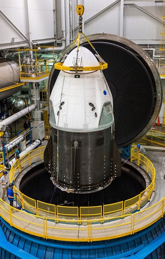
Vacuum Chamber
38 feet in diameter by 62 feet tall, vertical stainless steel chamber.
Test Volume
33 feet in diameter by 55 feet tall, usable test volume.
Vacuum Range
10-7 torr, long duration vacuum capability (Local atmospheric pressure to 100 statue miles altitude).
Thrust Capability
Up to 100,000 lbf of thrust nominal, 400,000 lbf of thrust maximum.
Thermal Conditioning
Vacuum chamber surfaces are lined with a liquid nitrogen cold wall, capable of maintaining -320 °F. A quartz infrared heating system can be programed to radiate a sinusoidal distribution, simulating rotational solar heating.
Chamber Access
27 foot diameter top hatch for equipment loading, two 6.5 foot personnel entry doors.
Spray Chamber
Cooling chamber, 67 foot diameter by 120 foot deep, located immediately below the vacuum chamber containing 1.75 million gallons of chilled water. Deluge system cools exhaust gases at a rate of 250,000 gallons per minute with 11,000 horsepower of pumping capacity.
Supply Systems – Dedicated on-site storage includes:
- 33,000 gallons liquid hydrogen
- 12,000 gallons liquid oxygen
- 56,000 gallons liquid nitrogen for operation of the vacuum cold wall
- Approximately 310,000 standard cubic foot (scf) gaseous nitrogen, at up to 4,000 pounds per square inch gauge (psig) storage pressure, with additional tube trailer stations available.
- Approximately 210,000 scf gaseous helium, including 70,000 scf at up to 5,000 psig storage pressure, with additional tube trailer stations available.
- Capability to accommodate liquid methane operations.
Altitude Exhaust Systems
- Two, three-stage steam-operated ejector systems provide hot fire altitude simulation up to 100,000 feet altitude.
- The system can also simulate launch ascent pressure profile.
- Exhaust system can accommodate a variety of upper stage propellant combinations including, but not limited to, liquid hydrogen, liquid oxygen, liquid methane, hydrogen peroxide, and RP-1.
Test Control
Control room located 2,600 feet from the test site.
Summary
- Single Position, Vertical Testing Capability
Altitude Testing Capability over 95 K ft - Propellants: GH2, GOX, LH2, LOX, LCH4
- Maximum Thrust – 400 K lbf