


By Dr. Dexter Johnson (retired)
POC: Teresa Kinney teresa.l.kinney@nasa.gov
Utilizing reduced-order dynamic math models (DMM) in linear system-level dynamic analyses is a well-known practice that enables extreme computational efficiencies. But what about nonlinear system dynamics? Reduced-order DMMs have found their way into contact dynamics. The engineer must look no further than the Henkel-Mar pad separation analysis methodology to verify this fact. More sophisticated applications of DMMs in contact dynamics are possible when certain repetitive geometry pattens are present. For example, Figure 1 shows a type of pipe known as a “flexible” pipe used by the subsea industry. This design features four layers of helically wound steel wires that provide the pipe with its stick/slip behavior during bending, thereby enabling a longer fatigue life in harsh ocean environments. With these helically wound armor layers presenting a repetitive contact topology, contact surfaces can be constructed and tracked enabling the friction logic to operate resulting in the friction hysteretic moment-curvature plot provided in Figure 1 (top).
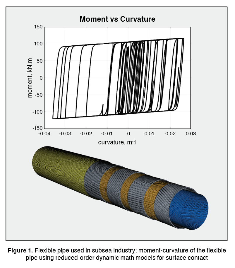
As seen from Figure 1, the pipe was subjected to many bending cycles and executed in essentially a real-time computation. A single bending cycle of the same pipe in full finite element model (FEM) resolution (i.e., no use of DMMs) would require 48 hours of computation on 36 central processing units (CPUs) running in parallel given the very large order of the FEM.
What about utilizing DMMs for computationally efficient nonlinear dynamics involving large displacements and rotations? Before addressing this question, the residual flexibility mixed boundary transformation (RFMB1) must be defined. The RFMB coordinate transformation is given as follows:
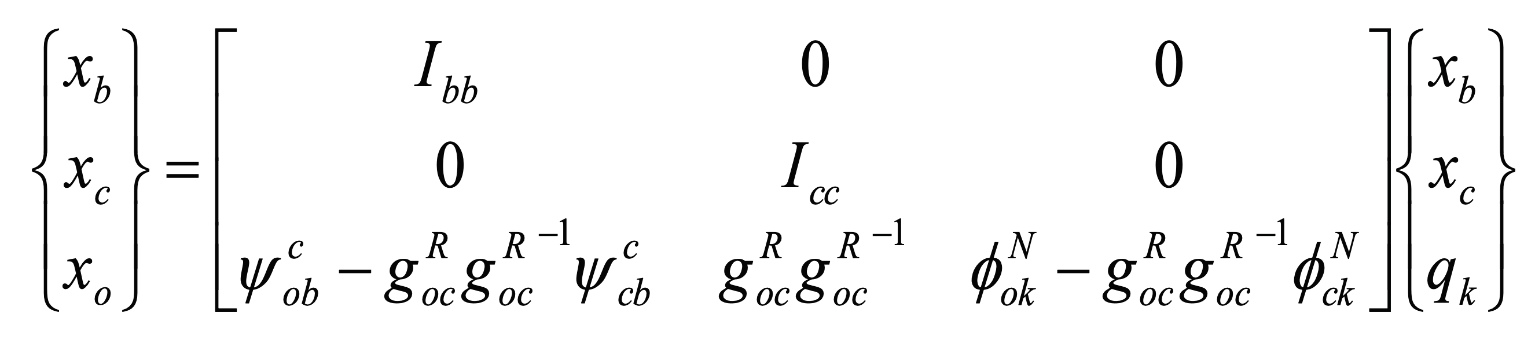
The transformation is a mix of the following submatrices: constraint modes (ψ) due to unit displacements on the b-set boundary degrees of freedom (DoFs) that remain fixed during the eigenvalue problem, residual flexibility (g) due to unit forces at the c-set boundary DoFs that remain free during the eigenvalue problem, and a truncated set of normal modes (φ) computed with the b-set DoFs constrained. It can be shown that the transformation retains full flexibility at the DMM physical DoFs and retains the full dynamics of the FEM up to the user-selected truncation frequency for the normal modes. The reduction of DoFs, and hence the computational efficiency, arises from the number of kept modes (k) being significantly less than the number of interior FEM DoFs.
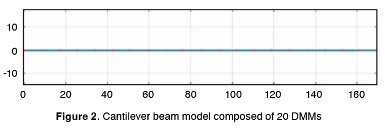
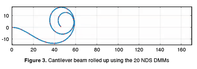
To enable DMM large displacements/rotations, four coordinates are added to the above RFMB to track large rotations. These quaternions replace the rigid-body modes that are only valid for infinitesimal rotations. With this process, the RFMB is transformed into a nonlinear dynamic substructure (NDS). Solution algorithms need to be modified accordingly as well to allow for equilibrium iterations since the problem now is highly nonlinear. As an example, consider the undeformed cantilever beam model (Figure 2) composed of 20 DMMs (single DMM of a beam composed of 5 CBAR elements repeated 20x).
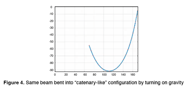
A moment is applied at the free end (right end) of Figure 2. While small displacement theory is limited and breaks down after a few degrees of rotation, the cantilever beam can be completely rolled up using NDS (see Figure 3) in a highly nonlinear dynamic simulation. Also note that the entire nonlinear dynamic simulation was executed in seconds on a laptop and included all dynamic effects. Similarly, the beam can be bent into a “catenary-like2” shape by turning on gravity and enforcing displacements at each end to the required coupling location (see Figure 4).
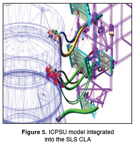
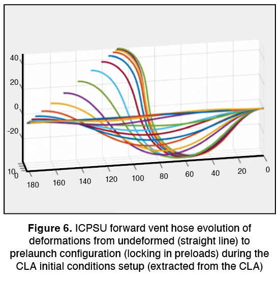
One application for this large displacement/rotation NDS capability has been to include umbilical models in the coupled loads analysis (CLA) framework. Figure 5 shows the Interim Cryogenic Propulsion Stage (ICPS) umbilical that was integrated into the Space Launch System (SLS) CLA. The SLS CLA is an integrated assembly of various component DMMs (boosters, core stage, mobile launcher (ML), upper stage, etc.) to which the ICPS umbilical (ICPSU) and its hoses as NDS DMMs can now be added. For each hose, one end connects to the SLS vehicle and the other end to the ML structure. As an example, Figure 6 shows the evolution of the deformations of the forward vent hose (modeled with 20 NDS DMMs) as it goes from the undeformed geometry (straight line) into its prelaunch geometry during the initial condition setup in the CLA.
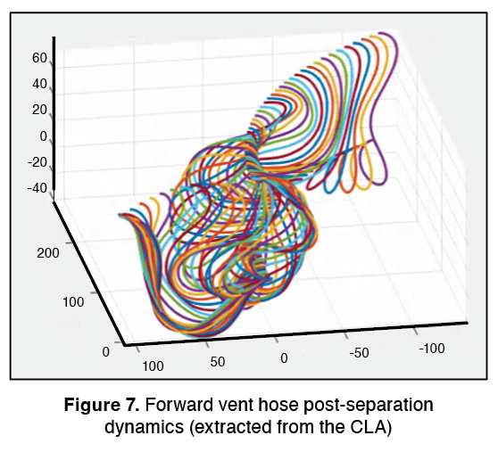
As the timed command for umbilical separation is given, the vehicle-side ground plate separates (using the Henkel-Mar contact/separation algorithm) and the ML gantry rotates the separating umbilical away from the already lifting vehicle (the gantry was brought into the CLA as a NDS capable of large rotations). Figure 7 captures the post-separation forward vent hose dynamics (extracted from the CLA). From this, 100 ICPSU hose clearances to the lifting vehicle can be computed.
The power of the reduced-order models does not end with linear dynamics. It is possible to introduce large displacements and rotations into reduced-order models to enable seamless integration into large substructured integrated system dynamic analyses such as a CLA. For the specific case of the SLS, this capability allowed us to integrate umbilicals into the CLA to more accurately capture the impact of system flexibilities, dynamic response to forcing functions, pad separation “twang” effects, ML dynamics, and gantry/umbilical timings on clearances.
For information, contact Teresa Kinney teresa.l.kinney@nasa.gov