
















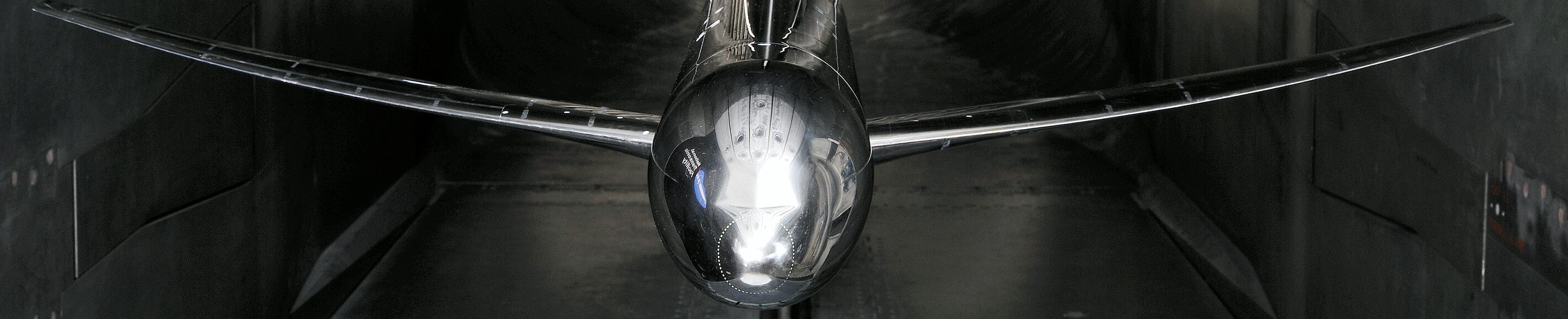
This website is currently under construction.
Please see the full NASA Common Research Model website for current information.
High Speed CRM Geometry
After much discussion, the SFW TWG agreed that the CRM should be based on a transonic transport configuration designed to fly at a cruise Mach number of M=0.85 with a nominal lift condition of CL=0.50, and at a Reynolds number of Rn=40 million per reference chord.
They also specified that the wing should have an aspect-ratio of AR=9.0, and a taper-ratio of λ=0.275. Additionally, the span should be sized accordingly to integrate into an existing fuselage model. The side-of-body is nominally at 10% semispan and the yehudi break occurs at the 37% station. The trailing-edge (TE) thickness is non-zero to accommodate a minimum-gauge model fabrication constraint of 0.014 inches; at the wingtip, this results in a 0.48% thick TE base.
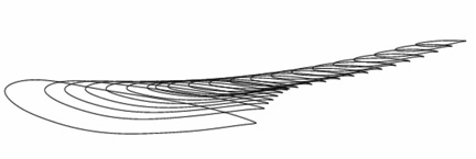 Airfoil Stack for the CRM Wing | This figure above depicts a side-view of the airfoil stack as rigged in the fuselage reference plane. |
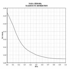 Non-Dimensional Thickness Distribution of the CRM Wing | The next figure illustrates the non-dimensional max thickness distribution across the wing; the average non-dimensional thickness of the exposed wing is about 10.8%. |
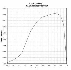 Max-Camber Distribution of the CRM Wing | The third figure gives the max-camber distribution. Note that the outboard wing carries supercritical airfoil sections with about 1.5% camber. |
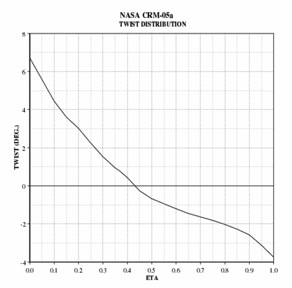 Twist Distribution of the CRM Wing | The fourth figure shows the wing’s twist distribution and indicates that the wing is washed out about 8 degrees from side-of-body to wingtip. |
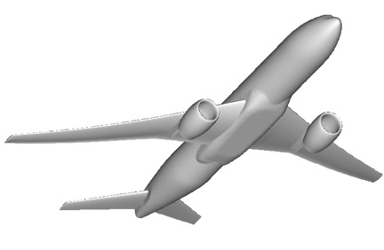 CRM Wing/Body/Nacelle/Pylon/Horizontal-Tail Configuration | The final figure illustrates the integration of the horizontal tail and nacelle/pylons into the wing/body/nacelle/pylon/horizontal-tail (WBNPH) configuration of the CRM. |
Related Files and Data
This list contains the original CAD files in both iges and stp formats for both full scale and model scale.
- crm.eta65.unswept31.5deg.blunt+sharp.te.README.txt
- This file explains the simple-sweep transformations and corresponding 2D flow conditions that apply.
- crm.eta65.unswept31.5deg.blunt+sharp.te.plots.pdf
- This file provides some airfoil geometric characteristics and compares the two sections.
- crm.eta65.unswept31.5deg.blunt+sharp.te.igs
- This file is an IGES file which contains the two airfoil sections.
- The *.p3d and *.te.txt points below reside on the IGES
- crm.eta65.unswept31.5deg.blunt+sharp.te.fit.p3d
- This file contain the set of discrete points in Plot3D format. Both the Sharp and the Blunt TE airfoils are included in this file.
- crm.eta65.unswept31.5deg.blunt.te.txt and crm.eta65.unswept31.5deg.sharp.te.txt
- Theses files contain the set of discrete points in text format.
Finite Element Models (FEM) of the NASA CRM model are available below:
NTF Wind Tunnel Model with Nacelle/Pylon and Horizontal Tail = 0 deg incidence angle.
Wing/Body/Nacelle/Pylon/Tail=0 Configuration
These files contain the full model configuration.
A Patran database file is also available but is quite large. If you would like to obtain this database file, please send an email to s.m.rivers@nasa.gov.
- CRM-mode-tet4-001-den.bdf
- CRM-mode-tet4-001-den.f06
- CRM-free-tet4-001-den.bdf
- CRM-gload-tet4-001-den.bdf
NTF Wind Tunnel Model with Horizontal Tail = 0 deg incidence angle.
Wing/Body/Tail=0 deg Configuration
- CRM-mode-tet4-001-den-noEng_sk.bdf
- This file contains only the wing/body/tail=0 deg configuration without the nacelle/pylons
- CRM_30_Modes_first_half.tar and CRM_30_Modes_second_half.tar
- Modal analysis obtained for the first 30 modes of the CRM Wind Tunnel Model using the file above at the University of Wyoming are given in these files.
NTF Wind Tunnel Model Wing/Body Only
Wing Body Alone Configuration
- CRM-no-nacells-mode-tet4-003.bdf
- This file contains only the wing/body configuration without the nacelle/pylons or horizontal tail.
Wingbox FEM Files
- CRM_wingboxFEM_description.pdf
- CRM_V12wingbox_1
- CRM_V14wingbox_1_noHM
- CRM_V15wingbox_1_noHM
- CRM_Matlabwingbox_1
- CRM_Wingbox_FEMMidsurfaces_IGES
The hyper mesh files have been removed from V14 and V15. If you would like these files, send an email to s.m.rivers@nasa.gov to request them.
This vertical tail geometry was generously provided by ONERA. The CAD files included are a CATPart file and an igs file. Some views of the tail integrated into the fuselage are also included in the CAD files. The Design Report provides the details of the design of the vertical tail.
To download the free Adobe Reader please click here.