


Chapter Contents
- Chapter Glossary
- 4.1 Introduction
- 4.2 Public Data Sources and Disclaimers
- 4.3 Definitions
- 4.4 Technology Maturity
- 4.5 Overview of In-Space Propulsion Technology Types
- 4.6 State-of-the-Art in Small Spacecraft Propulsion
- References
Chapter Glossary
| (ABS) | Acrylonitrile Butadiene Styrene | |
| (AC) | Alternating Current | |
| (ACO) | Announcement for Collaborative Opportunity | |
| (ACS) | Attitude Control System | |
| (ADN) | Ammonium Dinitramide | |
| (AFRL) | Air Force Research Laboratory | |
| (AIS) | Applied Ion Systems | |
| (AOCS) | Attitude and Orbit Control System | |
| (AR) | Aerojet Rocketdyne | |
| (ARC) | Ames Research Center | |
| (ACE) | Astra Spacecraft Engine | |
| (BOL) | Beginning of Life | |
| (CHIPS) | CubeSat High Impulse Propulsion System | |
| (CMNT) | Colloid MicroNewton Thrusters | |
| (CNAPS) | Canadian Nanosatellite Advanced Propulsion System | |
| (CNES) | French National Center for Space Studies | |
| (CPOD) | CubeSat Proximity Operations Demonstration | |
| (CUA) | CU Aerospace LLC | |
| (DFMR) | Design for Minimum Risk | |
| (DRM) | Design Reference Mission | |
| (DSSP) | Digital Solid State Propulsion LLC | |
| (EOL) | End of Life | |
| (EMC) | Electromagnetic Compatibility | |
| (EMI) | Electromagnetic Interference | |
| (EP) | Electric Propulsion | |
| (EPL) | Electric Propulsion Laboratory, Inc. | |
| (EPSS) | Enabling Propulsion System for Small Satellites | |
| (ESA) | European Space Agency | |
| (ESP) | Electrically Controlled Solid Propellant | |
| (FASTSAT) | Fast, Affordable, Science and Technology Satellite | |
| (FEEP) | Field Emission Electric Propulsion | |
| (FPPT) | Fiber-Fed Pulsed Plasma Thruster | |
| (GEO) | Geostationary Equatorial Orbit | |
| (GIT) | Gridded-ion Thrusters | |
| (GOCE) | Gravity Field and Steady-State Ocean Circulation Explorer | |
| (GOX) | Gaseous Oxygen | |
| (GPIM) | Green Propellant Infusion Mission | |
| (GPS) | Global Positioning System | |
| (GRC) | Glenn Research Center | |
| (GSFC) | Goddard Space Flight Center | |
| (HAN) | Hydroxylammonium Nitrate | |
| (HET) | Hall-effect Thruster | |
| (HTP) | High Test Peroxide | |
| (HTPB) | Hydroxyl-terminated Polybutadiene | |
| (IPS) | Integrated Propulsion System | |
| (ISS) | International Space Station | |
| (JANNAF) | Joint Army Navy NASA Air Force | |
| (JHU ERG) | Johns Hopkins University Energetics Research Group | |
| (JPL) | Jet Propulsion Laboratory | |
| (LFPS) | Lunar Flashlight Propulsion System | |
| (LISA) | Laser Interferometer Space Antenna | |
| (MAPS) | Modular Architecture Propulsion System | |
| (MarCO) | Mars Cube One | |
| (MCD) | Micro-Cavity Discharge | |
| (MEMS) | Microelectromechanical System | |
| (MEO) | Medium Earth Orbit | |
| (MMH) | Monomethyl Hydrazine | |
| (MPUC) | Monopropellant Propulsion Unit for CubeSats | |
| (MSFC) | Marshall Space Flight Center | |
| (MVP) | Monofilament Vaporization Propulsion | |
| (N2O) | Nitrous Oxide | |
| (NEA) | Near-Earth Asteroid | |
| (NODIS) | NASA Online Directives Information System | |
| (NSTT) | Nanosat Terminator Tape | |
| (OTV) | Orbital Transfer Vehicle | |
| (PacSci EMC) | Pacific Scientific Energetic Materials Company | |
| (PBM) | Plasma Brake Module | |
| (PMD) | Propellant Management Device | |
| (PMDs) | Propellant Management Devices | |
| (PMI) | Progress toward Mission Infusion | |
| (PMMA) | Polymethyl Methacrylate | |
| (PPT) | Pulsed Plasma Thrusters | |
| (PPU) | Power Processing Unit | |
| (PTD) | Pathfinder Technology Demonstration | |
| (PTFE) | Polytetrafluoroethylene | |
| (PUC) | Propulsion Unit for CubeSats | |
| (ROMBUS) | Rapid Orbital Mobility Bus | |
| (SAA) | Space Act Agreement | |
| (SBIR) | Small Business Innovative Research | |
| (SCAPE) | Self Contained Atmospheric Protective Ensemble | |
| (SEP) | Solar Electric Propulsion | |
| (SMAP) | Soil Moisture Active Passive | |
| (SMART-1) | Small Missions for Advanced Research in Technology | |
| (SME) | Subject Matter Experts | |
| (SSTL) | Surrey Satellite Technology Ltd. | |
| (SSTP) | Small Spacecraft Technologies Program | |
| (TCMs) | Trajectory Correction Maneuvers | |
| (TMA) | Technology Maturity Assessment | |
| (TRL) | Technology Readiness Level | |
| (UTIAS) | University of Toronto Institute for Aerospace Research | |
| (VAT) | Vacuum arc thrusters | |
| (VENuS) | Vegetation and Environment monitoring on a New Microsatellite | |
| (WFF) | Wallops Flight Facility | |
4.1 Introduction
In-space propulsion devices for small spacecraft are rapidly increasing in number and variety. A surge in public and private investments in small spacecraft propulsion technologies, combined with the immaturity of the overall small spacecraft market, has resulted in an abundance of confusing, unverified, sometimes conflicting, and otherwise incomplete technical literature. Furthermore, the rush by many device developers to secure market share has resulted in uncertainty regarding the true readiness of these devices for mission infusion. As third parties independently verify device performance, and end-users demonstrate these new devices in their target environments, the true maturity, capability, and flight readiness of these devices will become clearer. In the meantime, this report will attempt to reduce confusion by compiling publicly described small spacecraft propulsion devices, identifying publicly available technical literature, highlighting missions of potential interest, and organizing the data to improve comprehension.
4.1.1 Document Organization
This chapter organizes the state-of-the-art in small spacecraft propulsion into the following categories:
- In-Space Chemical Propulsion (4.6.1)
- In-Space Electric Propulsion (4.6.2)
- In-Space Propellant-less Propulsion (4.6.3)
Each of these categories is further subdivided by prevailing technology types. These subsections organize each technology type as follows:
- Technology Description
- Key Integration and Operational Considerations
- Current & Planned Missions
- Summary Table of Devices
- Notable Advancements
The organizational approach introduces each technology, outlines key integration and operational considerations, highlights recent or planned missions that may advance flight readiness, and tabulates procurable devices. Some sections also include an incomplete list of notable advancements. While the key integration and operational considerations are not comprehensive, they provide insights that may influence propulsion system decisions.
4.2 Public Data Sources and Disclaimers
This chapter is a survey of small spacecraft propulsion technologies discussed in open literature and does not serve as an original source. As such, this chapter only considers literature found in the public domain to identify and classify propulsion devices. Commonly used sources for public data include manufacturer datasheets, press releases, conference papers, journal papers, public filings with government agencies, and news articles.
This chapter summarizes device performance, capabilities, and flight history, as presented in publicly available literature. Data not appropriate for public dissemination, such as proprietary, export controlled, or otherwise restricted data, are not considered. Actual device maturity and flight history may differ from what is documented herein. Device manufacturers should be consulted for the most up-to-date and relevant data.
This chapter’s primary data source is literature produced by device manufacturers. Unless otherwise stated, do not assume independent verification of device performance. Performance and capabilities described may be speculative or otherwise based on limited data.
The information presented is not intended to be exhaustive but rather to provide an overview of the current state-of-the-art technologies and their development status. It should be noted that technology maturity designations may vary with changes to payload, mission requirements, reliability considerations, and/or the environment in which performance was demonstrated. Readers are highly encouraged to reach out to companies for further information regarding the performance and maturity of these products. There is no intention of mentioning certain companies and omitting others based on their technologies or relationship with NASA.
The propulsion market is rapidly evolving, and the authors have limited time to thoroughly scour public databases. We increasingly depend on device manufacturers to provide corrections to NASA. Suggestions or corrections for this document should be submitted to the NASA Small Spacecraft Virtual Institute arc-sst-soa@mail.nasa.gov. for consideration prior to the publication of future issues.
4.3 Definitions
- Device refers to a component, subsystem, or system, depending on the context.
- Technology refers to a broad category of devices or intangible materials, such as processes.
4.4 Technology Maturity
4.4.1 Application of the TRL Scale to Small Spacecraft Propulsion Systems
NASA has a well-established guideline for performing Technology Maturity Assessment (TMA), described in detail in the NASA Systems Engineering Handbook (1). A TMA determines a device’s technological maturity, which is usually communicated according to the NASA Technology Readiness Level (TRL) scale. The TRL scale is defined in NASA Procedural Requirements (NPR) 7123 (2). The NASA Systems Engineering Handbook and NPR 7123 can be accessed through the NASA Online Directives Information System (NODIS) library. Assessment of TRLs for components, systems, or software allows for clear communication between technologists, program managers, and other stakeholders regarding the maturity of a technology. Furthermore, TRL is a valuable tool to communicate the risk associated with the infusing technologies into programs. For TRLs to be applied across all technology categories, the NASA TRL definitions are written broadly and rely on subject matter experts (SME) in each discipline to interpret appropriately.
Recently, U.S. Government propulsion SMEs proposed an interpretation of the TRL scale specifically for micro-propulsion. The Micro-Propulsion Panel of the JANNAF Spacecraft Propulsion Subcommittee in 2019 published the JANNAF Guidelines for the Application of Technology Readiness Levels (TRLs) to Micro-Propulsion Systems (3). The guideline was updated in 2022 to reflect the latest community input (4). This guideline suggests an interpretation of TRL for micro-propulsion and reflects both NASA and DoD definitions. The JANNAF panel consisted of participants from the Air Force Research Laboratory (AFRL), Glenn Research Center (GRC), Jet Propulsion Laboratory (JPL), and Goddard Space Flight Center (GSFC). The panel received further feedback from the non-Government propulsion community. While this JANNAF guideline focuses on micro-propulsion (e.g., CubeSats), it remains relevant for rigorously assessing TRLs across the broader category of small spacecraft in-space propulsion. By establishing a common interpretation of TRL for small spacecraft propulsion, technology maturity can be communicated more coherently and consistently between providers and stakeholders. The JANNAF guideline is open to unlimited distribution and may be requested from the Johns Hopkins University Energetics Research Group (JHU ERG). Ensure the use of the latest JANNAF guideline, as the guideline may continue to evolve with further community input.
A fundamental limitation of the JANNAF guideline for TRL assessment, and TMA in general, is the assumption of in-depth technical knowledge of the subject device. In the absence of detailed technical knowledge, especially in a broad technology survey as presented herein, a TMA may be conducted inaccurately or inconsistently. Furthermore, TRL assessment assumes an understanding of the end-user application. The same device may be assessed as being at different TRLs for infusion into different missions. For example, a device may be assessed at a high TRL for application to low-cost small spacecraft in low-Earth orbits, while it may be assessed at a lower TRL for application to geosynchronous communication satellites or NASA interplanetary missions due to differences in mission requirements. Differences in TRL assessment based on the operating environment may result from considerations such as thermal environment, mechanical loads, mission duration, or radiation exposure. Propulsion-specific variances between missions might include propellant type, total propellant throughput, throttle set-points, burn durations, and the total number of on/off cycles. As such, an accurate TRL assessment not only requires an in-depth technical understanding of a device’s development history, including specifics on past flight qualification activities, but also an understanding of mission-specific environments and interfaces. The challenge of assessing an accurate TRL in a broad technology survey poses a significant burden on data collection, organization, and presentation. Such activities are better suited for programs seeking to infuse new technologies into their missions.
Given the rapid evolution of small spacecraft propulsion technologies and the variety of mission environments, as well as generally limited technical details on devices in open literature, the propulsion chapter implements a novel system to classify technical maturity according to Progress toward Mission Infusion (PMI). This novel classification system is not intended to replace TRL but serves as a complementary tool to provide initial insight into device maturity when the TRL scale cannot yet be applied accurately and consistently. This novel classification system is discussed in detail below.
Readers are strongly encouraged to perform more in-depth technical research on candidate devices based on the most up-to-date information available, as well as to assess risk within the context of their specific mission(s). A thoughtful TMA based on the examination of detailed technical data through consultation with device manufacturers can reduce program risk and increase the likelihood of mission success. This survey is not intended to replace the readers’ own due diligence. Rather, this survey and PMI seek to provide early insights that may assist in down-selecting propulsion systems to a smaller set of candidate devices where an in-depth TMA becomes feasible.
4.4.2 Progress Toward Mission Infusion (PMI)
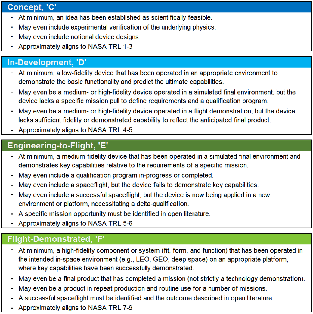
Rather than directly assessing a device’s technical maturity via TRL, propulsion devices described herein are classified according to evidence of progress toward mission infusion. This is a novel classification system first introduced in this survey. Assessing the PMI of devices in a broad survey, where minimal technical insight is available, may assist with down-selecting propulsion devices early in mission concept development. Once a handful of devices are identified as possible solutions for a specific mission concept, a detailed TMA and rigorous TRL assessment should be conducted. The PMI classification system sorts devices into one of four broad technology development categories: Concept, In-Development, Engineering-to-Flight, and Flight-Demonstrated. The following sections describe the PMI classification system in detail. Furthermore, Figure 4.1 summarizes the PMI classifications.
Concept, ‘C’
The Concept classification reflects devices in an early stage of development, characterized by feasibility studies and the demonstration of fundamental physics. Concept devices typically align with the NASA TRL range of 1 to 3. At a minimum, these devices are established as scientifically feasible, perhaps through a review of relevant literature and/or analysis. These devices may even include experimental verification that supports the validity of the underlying physics and notional designs. While Concept devices are generally not reviewed herein, noteworthy concept devices will be classified in tables with a ‘C’.
In-Development, ‘D’
The In-Development classification reflects most devices being actively matured by industry, where only a modest number of devices may progress to spaceflight. In-Development devices typically align with the NASA TRL range of 4 to 5. While In-Development devices may have specific applications identified by their developers, no selection for a specific mission has been publicly announced. In the absence of a specific mission, device development activities typically lack rigorous system requirements and independent requirement validation. Furthermore, qualification activities conducted in the absence of a specific mission typically require delta-qualification to address mission-specific requirements. At a minimum, In-Development devices are low-fidelity devices that have been operated in an appropriate environment to demonstrate basic functionality and support prediction of the device’s ultimate capabilities. They may even be medium- or high-fidelity devices operated in a simulated final environment, but lacking a specific mission pull to refine requirements and develop a robust qualification program. They may even be medium- or high-fidelity devices operated in a spaceflight demonstration but lack sufficient fidelity or demonstrated capability to reflect the anticipated final product. These devices are typically described as a technology push, rather than a mission pull. In-Development devices will be classified in tables with a ‘D’.
Engineering-to-Flight, ‘E’
The Engineering-to-Flight classification reflects devices with a publicly announced spaceflight opportunity. This classification does not necessarily imply greater technical maturity than the In-Development classification, but it does assume the propulsion device developer receives mission-specific requirements to guide final development and qualification activities. Furthermore, the Engineering-to-Flight classification assumes a mission team performed due diligence in the selection of a propulsion device, and the mission team regularly validates that the propulsion system requirements are met. Thus, while the PMI classification system does not directly assess technical maturity, there is an underlying assumption of independent validation of mission-specific requirements, where a mission team directly considers technical maturity in the process of device selection and mission infusion. Engineering-to-Flight devices typically align with the NASA TRL range of 5 to 6. At a minimum, these are medium-fidelity devices that have been operated in a simulated final environment and demonstrate key capabilities relative to the requirements of a specific mission. These devices may even be actively undergoing or have completed a flight qualification program. These devices may even include a spaceflight, but in which key capabilities were not demonstrated or further engineering is required. These devices may even include successful spaceflights, but the devices are now being applied in new environments or platforms that necessitate design modifications and/or delta-qualification. These devices must have one or more mission documented in open literature. Engineering-to-Flight devices will be classified in tables with an ‘E’.
Flight-Demonstrated, ‘F’
The Flight-Demonstrated classification reflects devices where a successful technology demonstration or genuine mission has been conducted and described in open literature. Flight-Demonstrated devices typically align with the NASA TRL range of 7 to 9. These devices are high-fidelity components or systems (in fit, form, and function) that have been operated in the target in-space environment (e.g., low-Earth orbit, GEO, deep space) on an appropriate platform, where all key capabilities were successfully demonstrated. These devices may even be final products, that have completed genuine missions (not flight demonstrations). These devices may even be in repeat production and routine use for several missions. The devices must be described in open literature as successfully demonstrating key capabilities in the target environment to be considered Flight-Demonstrated. If a device has flown, but the outcome is not publicly known, the classification will remain Engineering-to-Flight. Flight-Demonstrated devices will be classified in tables with an ‘F’.
4.5 Overview of In-Space Propulsion Technology Types
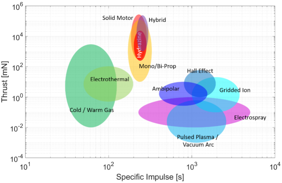
In-space small spacecraft propulsion technologies are generally categorized as (i) chemical, (ii) electric, or (iii) propellant-less. This chapter surveys propulsion devices within each technology category. Additionally, liquid-propellant acquisition and management devices are reviewed as an important component of in-space propulsion systems. Although other key subsystems have not yet been reviewed, such as power processing units, they may be included in future updates of this publication. Table 4-1 lists the in-space propulsion technologies reviewed. Figure 4.2 graphically illustrates the range of thrust and specific impulse for these small spacecraft propulsion devices. The thrust and specific impulse ranges provided in Table 4-1 and Figure 4.2 only summarize the performance of small spacecraft devices covered in this survey and may not reflect the broader capability of the technologies beyond small spacecraft or the limits of what is physically possible with further advancement. Furthermore, propulsion systems are often highly throttleable, and the devices surveyed herein may in many cases be capable of offering performance beyond the ranges presented in Table 4-1.
Chemical systems have enabled in-space maneuvering since the onset of the space age, proving highly capable and reliable. These include hydrazine-based systems, other mono- or bipropellant systems, hybrids, cold gas systems, and solid propellants. Typically, these systems are used when high thrust or rapid maneuvers are required. As such, chemical systems continue to be the in-space propulsion technology of choice when their total impulse capability is sufficient to meet mission requirements.
On the other hand, the application of electric propulsion devices has been historically more limited. While electric propulsion can provide an order of magnitude greater total impulse than chemical systems, research and development costs have typically eclipsed those of comparable chemical systems. Furthermore, electric propulsion generally provides thrust-to-power levels below 75 mN/kW. Thus, a small spacecraft capable of delivering 500 W to an electric propulsion system may generate no more than 38 mN of thrust. Therefore, while the total impulse capability of electric propulsion is generally considerable, these systems may need to operate for hundreds or thousands of hours, compared to the seconds or minutes required by chemical systems to achieve a similar impulse. That said, the high total impulse and low thrust requirements of many applications, such as station keeping, have maintained steady investment in electric propulsion over the decades. Only in recent years has the mission pull for electric propulsion reached a tipping point where it has overtaken chemical for specific in-space applications. Electric propulsion system types considered herein include electrothermal, electrospray, gridded ion, Hall-effect, pulsed plasma and vacuum arc, and ambipolar.
Propellant-less propulsion technologies such as solar sails, tethers, electric sails (and plasma brakes), and aerodynamic drag devices have long been investigated, but they have yet to move beyond small-scale demonstrations. However, growing needs such as orbital debris removal may offer compelling future applications.
Some notable categories are not covered in this survey, such as nuclear in-space propulsion technologies. While substantial investment continues in such areas for deep space science and human exploration, such technologies are generally at lower TRL and typically aim to propel spacecraft substantially larger than the 180 kg wet mass limit considered in this report.
Whenever possible, this survey considers complete propulsion systems, which are composed of thrusters, feed systems, pressurization systems, propellant management and storage, and power processing units, but not the electric power supply. However, for some categories, components (e.g., thruster heads) are mentioned without consideration of the remaining subsystems necessary for full implementation. Depending on the device’s intended platform (i.e., NanoSat, MicroSat, SmallSat), the propulsion system may be either highly integrated or distributed within the spacecraft. As such, it is logical to describe highly integrated propulsion units at the system level, whereas components of distributed propulsion systems may be logically treated at the sub-system level, where components from a multitude of manufacturers may be mixed and matched to create a unique mission-appropriate propulsion solution.
| Table 4-1: Summary of Propulsion Technologies Surveyed | ||
|---|---|---|
| Technology | Thrust Range | Specific Impulse Range [sec] |
| 4.6.1 CHEMICAL PROPULSION TECHNOLOGIES | ||
| Hydrazine Monopropellant | 0.25 – 28 N | 180 – 285 |
| Alternative Mono- and Bipropellants | 50 mN – 22 N | 150 – 310 |
| Hybrids | 8 – 222 N | 215 – 300 |
| Cold Gas | 10 μN – 3.6 N | 40 – 110 |
| Solid Motors | 37 – 461 N | 187 – 269 |
| Propellant Management Devices | – | – |
| 4.6.2 ELECTRIC PROPULSION TECHNOLOGIES | ||
| Electrothermal | 0.1 mN – 1 N | 20 – 350 |
| Electrosprays | 20 μN – 20 mN | 225 – 3,000 |
| Gridded Ion | 0.1 – 20 mN | 500 – 3,000 |
| Hall-Effect | 0.25 – 55 mN | 200 – 1,920 |
| Pulsed Plasma and Vacuum Arc Thrusters | 4 – 500 μN | 87 – 3,200 |
| Ambipolar | 0.5 – 17 mN | 400 – 1,100 |
| 4.6.3 PROPELLANTLESS PROPULSION TECHNOLOGIES | ||
| Solar Sails | TBD | – |
| Tethers | TBD | – |
| Electric Sails | TBD | – |
| Aerodynamic Drag | TBD | – |
4.6 State-of-the-Art in Small Spacecraft Propulsion
4.6.1 In-Space Chemical Propulsion
In-space chemical propulsion systems represent the most well-established of the space propulsion technologies. Chemical propulsion systems generate thrust by accelerating high-pressure gas, created by combustion or propellant decomposition and accelerated through a nozzle to supersonic speeds. Chemical propulsion systems are designed to satisfy high-thrust impulsive maneuvers. They offer lower specific impulse compared to their electric propulsion counterparts but have significantly higher thrust-to-power ratios.
Hydrazine Monopropellant
- Technology Description
Hydrazine monopropellant systems use catalyst structures (such as S-405 granular catalyst) to decompose hydrazine to produce hot gases. Hydrazine thrusters and systems have been in extensive use since the 1960s. The low mass and volume of many heritage hydrazine propulsion systems make them suitable for small spacecraft buses, and some hydrazine thrusters used on large spacecraft may be appropriate as the main propulsion system for small spacecraft. Hydrazine thrusters typically achieve a specific impulse between 200–235 seconds for 1-N class or larger thrusters.
- Key Integration and Operational Considerations
Extensive Flight Heritage: Since hydrazine has been used extensively in spaceflight applications, the technology’s traits are well understood (5).
Extensive Component Ecosystem: A robust ecosystem of components and experience exists because hydrazine systems are widely used. As such, hydrazine propulsion systems are frequently customized for specific applications using the available components.
Multiple Cold Restarts: These systems have typically been qualified for multiple cold starts.
Extensive Safety and Handling Requirements: Hydrazine and its derivatives are corrosive, toxic, and potentially carcinogenic. Its vapor requires the use of Self-Contained Atmospheric Protective Ensemble (SCAPE) suits. This overhead must be considered when planning ground-processing workflows for spacecraft and may impose undesirable constraints on the spacecraft, the launch provider, or other spacecraft participating in the same launch opportunity. Hydrazine propulsion systems typically incorporate redundant serial valves to prevent spills or vapor leaks, which might harm ground personnel or hardware.
- Current & Planned Missions
ArianeGroup has developed a 1-N class hydrazine thruster that has extensive flight heritage, including use on the ALSAT-2 small spacecraft (6) (7). The company also offers a 20-N hydrazine thruster with extensive flight history, although not with small spacecraft.
Aerojet-Rocketdyne (L3Harris company) has several small hydrazine thrusters with extensive flight histories. The 0.09-N MR-401, 1-N MR-103 series, 4-N MR-111G, and the 22-N MR-106L hydrazine thrusters are flight proven (8) (9) (10). In addition to four MR-107S 222-N thrusters, the OSIRIS-Rex spacecraft propulsion system has six MR-106L, sixteen MR-111G, and two MR-401 thrusters (11).
Moog has the 1-N MONARC-1, 5-N MONARC-5, and 22-N MONARC-22 series hydrazine thrusters (12). These thrusters have decades-long flight histories, although primarily as attitude control thrusters in larger satellites. NASA JPL’s Soil Moisture Active/Passive (SMAP) spacecraft used eight MONARC-5 thrusters (13).
Northrop Grumman has a line of hydrazine thrusters with long flight histories as attitude control thrusters for larger satellites. The thruster line includes the 0.4-N MRE-0.1, 4.4-N MRE-1.0, and 18-N MRE 4.0 (14).
Rafael offers 1-N, 5-N, and 25-N flight proven hydrazine thrusters (15).
IHI Aerospace offers the 1-N MT-9, 4-N MT-8A, and 20-N MT-2 flight proven hydrazine thrusters (16).
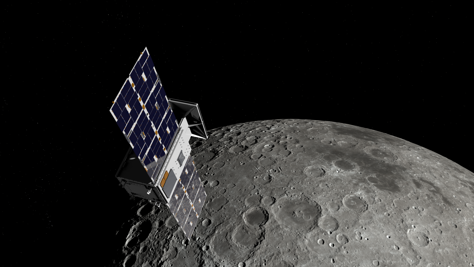
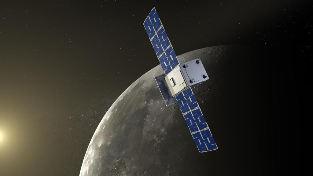
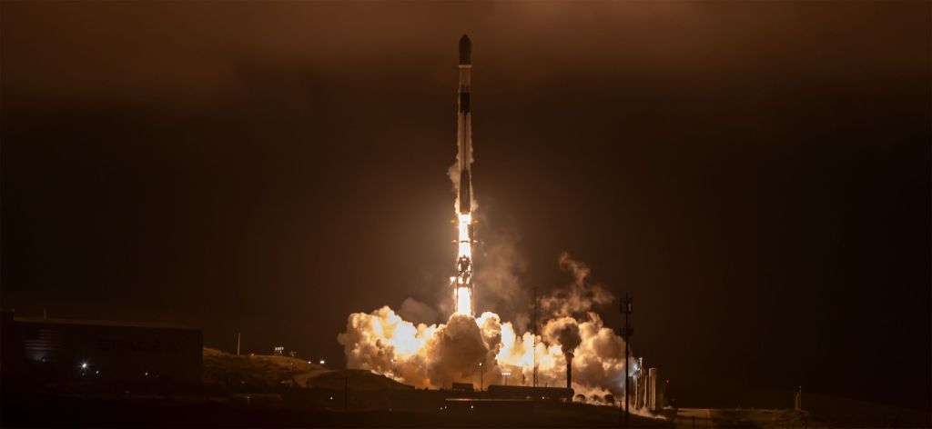
Stellar Exploration Inc. developed a customizable propulsion system for small satellites. A pump-fed hydrazine monopropellant version was supplied for the EchoStar EG3 spacecraft and the Cislunar Autonomous Positioning System Technology Operations and Navigation Experiment (CAPSTONE) spacecraft. The EchoStar nanosatellite built by Tyvak has been successfully commissioned and placed in orbit (17). The CAPSTONE spacecraft was similarly built by Tyvak and launched on a Rocket Lab Electron from New Zealand on 28 June 2022. The CAPSTONE spacecraft is a 12U, 25 kg CubeSat that will help reduce risk for future lunar spacecraft by validating navigation technologies and verifying the dynamics of a halo orbit. Although CAPSTONE experienced communication and propulsion challenges during the mission, the spacecraft achieved the expected lunar orbit (18) (19) (20).
- Summary Table of Devices
See Table 4-2 for current state-of-the-art hydrazine monopropellant devices applicable to small spacecraft.
Alternative Monopropellants and Bipropellants
- Technology Description
For the past several decades, Earth-storable propellants (i.e., storable at room temperature) have dominated in-space chemical propulsion systems, hydrazine for monopropellants and nitrogen tetroxide with either monomethylhydrazine or hydrazine for bipropellants. These propellants have the advantages of being ambient-temperature liquids (thus not requiring extensive thermal management) and easy to ignite (catalyst for hydrazine, hypergolic for bipropellants). However, due to the extensive handling and toxicity concerns of conventional chemical propellants, more propulsion systems using alternate propellants have been developed and adopted. Often described as “green” propellants, these alternative propellants are not necessarily benign but are not vapor hazards like conventional Earth-storable propellants and thus do not require specialized suits and breathing apparatus for handling.
Alternative monopropellants based on ionic liquids have received extensive technological development in recent years and have matured to flight-ready status. Ionic liquid monopropellants are ionic salts dissolved in water and blended with a fuel. Catalysts react the aqueous ionic salt and fuel blend for combustion. Thus, these formulations are not true monopropellants, since they have fuel and oxidizer components, but they are functionally no different than monopropellants.
The two mature ionic liquid monopropellant blends are LMP-103S, which is based on ammonium dinitramide (ADN) and ASCENT (Advanced Spacecraft Energetic Non-Toxic), formally referred to as AF-M315E, which is based on Hydroxylammonium Nitrate (HAN). These monopropellants do not present a vapor hazard and can be handled with conventional personal protection equipment (gloves, face shield). Depending on the formulations, they can also offer higher specific impulse and higher density-specific impulse than monopropellant hydrazine. The challenges with ionic liquid monopropellants are that their catalysts require more preheating than hydrazine and their higher combustion temperatures require higher temperature, more expensive catalyst and chamber materials. The ionic liquid monopropellants are not drop-in replacements for hydrazine, although their propulsion system components are similar.
Hydrogen peroxide is a high-density liquid that can be catalytically decomposed exothermically like hydrazine. Hydrogen peroxide does not present a vapor hazard, although high concentrations (>90%) can rapidly react with impurities in storage containers. Hydrogen peroxide was used extensively in the early days of space propulsion before losing favor to higher-performing hydrazine. It is now being examined again as a nontoxic alternative to hydrazine. Development efforts have focused on high-test peroxide (HTP), which has concentrations from 85–98%.
Green bipropellant combinations have also been developed, particularly for small spacecraft propulsion. For example, hydrogen peroxide and nitrous oxide have been explored as an oxidizer with alcohol as the fuel. Another example is an electrolysis system that breaks down liquid water into gaseous hydrogen and oxygen, which serve as fuel and oxidizer, respectively.
- Key Integration and Operational Considerations
Improved Hazard Safety Classifications: Air Force Range Safety AFSPCMAN91-710 (21) requirements state that if a propellant is less prone to external leakage, which is often seen with the ionic liquid “green” propellant systems due to higher viscosity, then the hazardous classification is reduced. External hydrazine leakage is considered “catastrophic,” whereas using ionic liquid green propellants reduces the hazard severity classification to “critical” and possibly “marginal” per MIL-STD-882E (Standard Practice for System Safety) (22). A classification of “critical” or less only requires two seals to inhibit external leakage, meaning no additional latch valves or other isolation devices are required in the feed system (22). While these propellants are not safe for consumption, they have been shown to be less toxic compared to hydrazine. This is primarily due to green propellants having lower vapor pressures, being less flammable, and producing more benign gases (such as water vapor, hydrogen, and carbon dioxide) when combusted.
Simplified Safety and Handling Requirements: Fueling spacecraft with green propellants, generally permitted as a parallel operation, may require a smaller exclusion zone, allowing for accelerated launch readiness operations (23). These green propellants are also generally less likely to undergo exothermic decomposition at room temperature due to higher ignition thresholds. Therefore, they require fewer inhibit requirements, fewer valve seats for power, and less stringent storage temperature requirements. The reduced hazard associated with some of these propellants may enable projects to take a Design for Minimum Risk (DFMR) approach to address propulsion system safety concerns, but only with the support of associated range and payload safety entities.
Immature Component Ecosystem: While there are thrusters that are relatively mature, incorporating them into integrated propulsion systems is challenging, and the maturity of standalone propulsion systems has lagged the pace of component development. Historically, research and development efforts, such as Small Business Innovation Research (SBIR) efforts, have focused on component development, and not the entire system. Efforts are now being made to focus on the development of system solutions. Most of these non-toxic propellants are still in some phase of development. Additionally, data on the propellants are widely restricted. Therefore, a comprehensive, public, peer-reviewed database of compatible materials does not currently exist, and prospective system developers using these propellants may have difficulty accessing such data to guide their efforts.
Other Considerations for Green Propellants: Other “green” propellants such as Hydrogen Peroxide, High Test Peroxide (HTP), and HTP/Alcohol bipropellants also have their own unique handling considerations. For instance, HTP is a strong oxidizer and can exothermically decompose rapidly if improperly stored or handled. Hydrogen Peroxide, however, has been used as a rocket propellant for many decades, and there is extensive information on safe handling, materials selection, and best practices. Electrolyzed water is another propellant option, wherein water is decomposed into hydrogen and oxygen and combusted as a traditional bipropellant thruster. However, generating and managing the power required to electrolyze the water in a compact spacecraft presents unique challenges. Yet it does provide a safe-to-launch system with very benign constituents.
- Current & Planned Missions
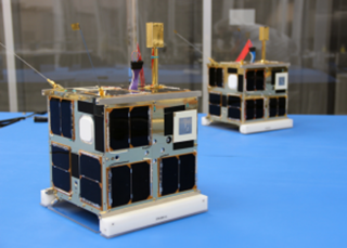
ECAPS offers a range of High-Performance Green Propulsion (HPGP) thrusters, including the LMP-103S (Figure 4.3), at 100-mN, 1-N, 5-N, and 22-N thrust levels. The 1-N HPGP thrusters were first demonstrated on orbit in the Prototype Research Instruments and Space Mission technology Advancement (PRISMA) mission completed in June 2011. PRISMA consisted of two small satellites, each carrying hydrazine and HPGP systems to enable a side-by-side comparison of their performance (24).
ECAPS developed an LMP-103S based propulsion system for a constellation of Earth observing satellites, called SkySat. SkySat has a propulsion system that uses four 1-N HPGP thrusters. As of 2018, thirteen SkySat satellites with the ECAPS propulsion system had been launched and were fully operational (25).
The ECAPS LMP-103S propulsion system is also used on the Autoscale demonstration of rendezvous technologies called ELSA-d, which launched in March 2021. ELSA-d has eight 1-N ECAPS HPGP thrusters to provide re-orbiting and de-orbiting capability. A system issue impacted three of the eight ECAPS thrusters and an unresolved root cause resulted in the loss of a fourth thruster. Nevertheless, many mission goals were successfully accomplished, improving the provider’s readiness for offering a commercial deorbit service (26).

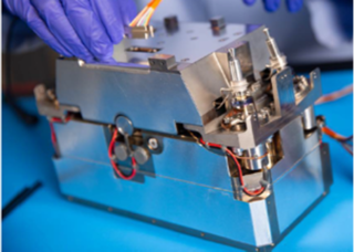
VACCO provided a hybrid Micro Propulsion System (MiPS) for the ArgoMoon 6U CubeSat built for the Italian Space Agency. The ArgoMoon MiPS, Figure 4.4, has an ECAPS 100mN LMP-103S thruster with four VACCO 25-mN R134a cold gas thrusters. ArgoMoon was successfully deployed in the Artemis I mission in November 2022 (27) (28) (29).
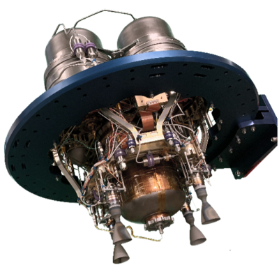
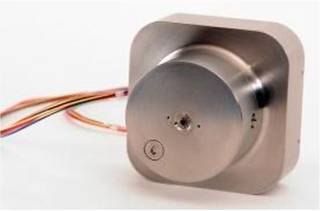
Aerojet-Rocketdyne built the ASCENT-based propulsion system for the NASA Green Propellant Infusion Mission (GPIM). GPIM was an on-orbit demonstration of the ASCENT (then called AF-M315E) propulsion system, using five 1-N thrusters (Figure 4.5) for small attitude control maneuvers (30). GPIM was integrated into a small spacecraft bus (Ball Aerospace’s BCP-100) and launched in June 2019 as a secondary payload on a Falcon Heavy. The five thrusters were successfully fired in space, across a range of operating modes, demonstrating attitude control and orbital inclination change capability (31).
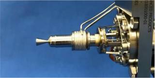
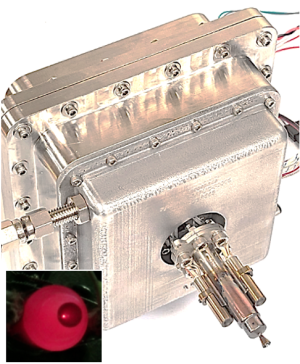
The Lunar Flashlight Propulsion System (LFPS), an ASCENT based propulsion system, was developed for the JPL Lunar Flashlight mission (32). Lunar Flashlight (Figure 4.6) was launched as a secondary payload in a December 2022 Falcon 9 launch, to map the lunar south pole for volatiles. LFPS was a pump-fed monopropellant system, using four 0.1-N ASCENT thrusters (Figure 4.7) built by Rubicon Space Systems (a division of Plasma Processes) and a micro-pump built by Flight Works Inc. The propellant management system was fabricated using additive manufacturing. During the first few days of flight, it was found that three of the four thrusters were underperforming. Based on ground testing, it was thought the underperformance might have been caused by obstructions in the propellant lines that limited propellant flow to the thrusters. Improvements were seen by increasing fuel pump pressure to clear the suspected obstructions. However, the effort was not sufficient to keep the spacecraft in the vicinity of the Moon, and the mission was terminated in May 2023 (33).
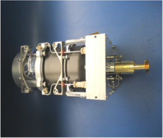
Benchmark Space Systems offers thrusters that can be used with High Test Peroxide (HTP) as a monopropellant or as an oxidizer in a bipropellant combination with fuel. Benchmark provided a bipropellant Halcyon Avant propulsion system (Figure 4.8) that uses four 22-N thrusters using HTP and isopropyl alcohol for the Sherpa-LTC2 orbital transfer vehicle (OTV) (34). The Sherpa-LTC2 was launched on a Falcon 9 in September 2022. The OTV was used to elevate the orbit of the Varuna Technology Demonstration Mission satellite (35). In June 2021, three monopropellant HTP Halcyon systems were launched aboard the SpaceX Transporter 2 rideshare mission. One of the systems debuted Orbit Fab’s RAFTI refueling kit as part of their Tenzing mission. The other two missions supported an undisclosed mission partner (36).
CisLunar Explorer, part of a NASA Centennial Challenges program, will use a water electrolysis propulsion system developed by Cornell University’s Space Systems Design Studio on a pair of 3U CubeSats. In this system, the water is electrolyzed in the propellant tank. The gaseous hydrogen/gaseous oxygen mixture is flowed through a flame arrestor into the combustion chamber, where it is ignited by a glow plug (37). The CubeSat was originally intended to be launched on Artemis I, but difficulties during integration bumped it from the mission (38) (39).
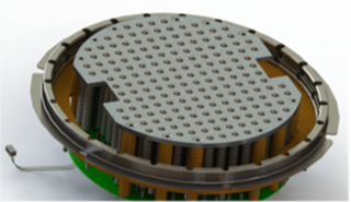
NASA’s Small Spacecraft Technology (SST) program at Ames Research Center (ARC) launched the first Pathfinder Technology Demonstration (PTD) mission in January 2021 (40) (41). PTD-1 (Figure 4.9) tested the HYDROS-C water electrolysis propulsion system, developed by Tethers Unlimited Inc. With a volume less than 2.4U, the HYDROS-C uses water as propellant. In-orbit, water was electrolyzed into oxygen and hydrogen, then combusted like a traditional bipropellant thruster. Limited performance data has been evaluated and made public (42). The system requires 10–15 minutes of recharge time between pulses. A variant of the HYDROS-C system is the HYDROS-M system, which is intended to be sized for MicroSats. Tethers Unlimited became a subsidiary of ARKA Group LP in 2020.

NanoAvionics developed an ADN-based monopropellant propulsion system under the Enabling Propulsion System for Small Satellites (EPSS) program. The EPSS monopropellant system was demonstrated on LituanicaSAT-2, a 3U CubeSat, to correct orientation and attitude, avoid collisions, and extend orbital lifetime. LituanicaSAT-2 was launched in June 2017 and successfully separated from the primary payload (Cartosat-2) as part of the European QB50 initiative. According to product literature, multiple missions have since launched (43) (44).
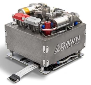
Dawn Aerospace has developed the CubeDrive bipropellant (nitrous oxide and propylene) system that consists of a single B1 thruster, propellant tank, valves, and electronics. The thruster can also be operated in cold gas mode (for smaller impulse bits) by not engaging the spark igniter. The 0.8U (Figure 4.10) to 4U configurations provide 425 to 3,500 N-s of total impulse, respectively (45).
- Summary Table of Devices
See Table 4-3 for the current state-of-the-art in other mono- and bipropellant devices applicable to small spacecraft.
- Notable Advances
CU Aerospace (CUA) has developed the Monopropellant Propulsion Unit for CubeSats (MPUC) system, Figure 4‑11. The monopropellant is an H2O2-ethanol blend denoted as CMP-X. Tests on a thrust stand with a bladder-fed propellant tank demonstrated continuous thrust for greater than 50 minutes at a thrust level of 250 mN and specific impulse of 179 s with an average input power of ~6 W during catalyst warmup. 1.5U and 2U system designs have an estimated 1400 N-s and 2120 N-s total impulse, respectively. A ~900°C flame temperature allows the thrust chamber to use nonrefractory construction materials. CMP-X has low toxicity and was subjected to UN Series 1, 2, 3, and 6 testing; CMP-X demonstrated no detonation propagation when confined under a charge of high explosive, it exhibited thermal stability with no explosion or detonation during bonfire testing, and was not sensitive to drop impact or friction. CMP-X passed the criteria for either a 1.4S or a “Not Class 1” determination and may be excluded from the explosive class. Long-term storage testing shows no degradation over >1,200 days. This additively manufactured thruster passed environmental (vibration and thermal vacuum) testing and post-environmental thrust data were within experimental error of the pre-environmental data (47).
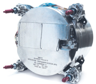
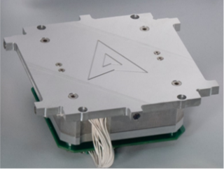
VACCO has integrated four ECAPS 1-N LMP-103S thrusters into their Integrated Propulsion System (IPS) (Figure 4.12), a bolt-on propulsion module for delta-V and attitude control applications (48) (49).
Hybrids
- Technology Description
Hybrid propulsion is a mix of solid and liquid/gas forms of propulsion. In a hybrid rocket, the fuel is typically a solid grain, and the oxidizer (often gaseous oxygen) is stored separately. The rocket is then ignited by injecting the oxidizer into the solid motor and igniting it with a spark or torch system. Since combustion can only occur while the oxidizer is flowing, these systems can readily be started or shut down by controlling oxidizer flow.
- Key Integration and Operational Considerations
- Improved Safety and Handling: Hybrid systems are inherently safer to handle than solid motor systems because there is no oxidizer pre-mixed into the solid motor, which reduces the risk of premature ignition.
- Integrates Attributes of Solids and Liquids: Hybrids achieve many positive attributes of both solid motors (storability and handling) and liquid engines (restart and throttling).
- Combustion Efficiency: Combustion efficiency tends to be lower than either solid motors or liquid engines.
- Other Drawbacks: Regression rate control and fuel residuals tend to be more problematic in hybrid designs.
- Current & Planned Missions
An arc-ignition “green” CubeSat hybrid thruster system prototype was developed at Utah State University and demonstrated in flight under the Undergraduate Student Instrument Project (USIP). The hybrid rocket design used a 3D-printed acrylonitrile butadiene styrene (ABS) plastic as the fuel and high-pressure gaseous oxygen (GOX) as the oxidizer. For safety considerations, the oxidizer was diluted to 60% nitrogen and 40% oxygen for the demonstration. On March 25, 2018, the system was successfully tested aboard a sounding rocket launched from NASA Wallops Flight Facility (WFF) into space and the motor was successfully re-fired five times. During the tests, 8 N of thrust and a specific impulse of 215 s were achieved as predicted (50) (51). The Space Dynamics Lab has miniaturized this technology to be better suited for CubeSat applications (0.25-0.5 N).
- Summary Table of Devices
See Table 4-4 for current state-of-the-art hybrid devices applicable to small spacecraft.
- Notable Advances
Utah State University has tested Nytrox, a blend of nitrous oxide and oxygen, and ABS. The testing was focused on a 25–50 N system for a 12U sized vehicle. Investigating different nozzle materials for low erosion in long duration burns is a key concern (52) (53).
JPL developed a hybrid propulsion system for a 12U CubeSat and a 100 kg SmallSat. Testing included regression rate characterization of clear and black polymethyl methacrylate fuels with GOX to be included in propulsion system sizing. Vacuum testing included an improvement of the ignition system to a laser-operated system that eliminates the need for a separate ignition fuel gas (54) (55) (56) (57).
NASA ARC developed a polymethyl methacrylate (PMMA) and nitrous oxide hybrid system that used ethylene and nitrous oxide thrusters. The ethylene and nitrous oxide also function as the hybrid ignition source. The hybrid system had a demonstrated efficiency of 91% and calculated specific impulse of 247 s, making it competitive with current small satellite propulsion systems (58) (59).
Aerospace Corporation and Penn State University developed an “Advanced Hybrid Rocket Motor Propulsion Unit for CubeSats (PUC)”. The design used additive manufacturing techniques for the carbon filled polyamide structure including the nitrous oxide tank and a paraffin grain within an acrylic shell, with acrylic diaphragms 3D printed in-situ in the grain for enhanced performance. This design fits in a 1U space, for a 3U or 6U spacecraft (60).
Parabilis Space Technologies developed two small satellite propulsion systems. Rapid Orbital Mobility Bus (ROMBUS) is a hybrid rocket-based system with nitrous oxide as the oxidizer and PMMA or hydroxyl-terminated polybutadiene (HTPB) as the fuel. It provides high-impulse thrust for satellite translational maneuvers which can be used for initial orbit insertion, rapid orbit rephasing, threat/collision avoidance, and targeted re-entry at the satellite’s mission end of life (61). Nano Orbital Transfer System (OTS) is a HTPB and nitrous oxide (N2O) hybrid system, with N2O-based ACS thrusters. Nano OTS leverages Parabilis’ proven hybrid engine and small satellite technologies for low-cost, high-performance maneuvers using non-toxic green propellants. The OTS has a modular design, enabling rapid and low-cost configuration of stages to accommodate 3U size NanoSats up to >50 kg MicroSat-size vehicles (62).
Cold Gas
- Technology Description
Cold gas propulsion systems are simple, mature, and safe, although they provide relatively limited total impulse. There is no combustion in cold gas systems, with thrust produced by expelling gaseous propellant through a diverging nozzle. Propellants can be stored as compressed gases, saturated liquids, or solids. Gaseous nitrogen is a commonly used propellant for cold gas systems, although many other gases have been used in the long history of cold gas propulsion. For gases, the tradeoff is between performance and storage; lower molecular weight gases offer higher specific impulse but require more voluminous storage. Saturated liquids are stored at low pressure and vaporized when introduced into a low-pressure chamber. The dense storage of saturated liquids and their property of self-pressurization has made them popular as a propellant for CubeSat missions. The liquid propellants may require a pressurant or are self-pressurized, if stored in a two-phase liquid-gas state. Solid propellants can be used in a cold gas system by subliming solid propellants with adequate heat.
A derivative of cold gas systems is electrothermal or “warm gas” systems, in which the propellant is somewhat heated without chemical reaction and accelerated through a nozzle. The additional heating results in a modest improvement in thrust and specific impulse compared to a pure cold gas system, but typically burdens the spacecraft with increased power consumption. Electrothermal systems are described in more detail in the Electric Propulsion section.
- Key Integration and Operational Considerations
- Low Cost and Complexity: Cold gas thrusters are often attractive and suitable for small buses due to their relatively low cost and complexity.
- Safe: Most cold gas thrusters use inert, non-toxic propellants, which is advantageous for secondary payloads that must adopt “do no harm” approaches to primary payloads.
- Small Impulse Bit: Cold gas systems are often well suited to provide attitude control since they can provide very small minimum impulse bits for precise maneuvering.
- Small Total Impulse: The low specific impulse of these systems limits their ability to provide large orbital correction maneuvers.
- Integrated Systems Optimized for CubeSats: Designs optimized around the limited resources of a CubeSat have improved the capability of these systems for small buses.
- Missions
The Micro-Electromechanical-based PICOSAT Satellite Inspector, or MEPSI, built by the Aerospace Corporation, flew aboard STS-113 in 2002 and STS-116 in 2006. The spacecraft included both target and imaging/inspector vehicles connected via a tether. The two vehicles were each 4 x 4 x 5 in3 in volume and had five cold-gas thrusters, producing approximately 20 mN. The MEPSI propulsion system was produced using stereo-lithography. It was suited as a propulsion research unit for PicoSats (63).
Marotta developed a cold gas micro-thruster, CGMT-000-9, for fine attitude adjustment maneuvers that flew on the NASA ST-5 mission in 2006. The thruster operated in blowdown mode with gaseous nitrogen, starting at 2.4 N and ending at 0.05 N (64) (65).
In June 2014, Space Flight Laboratory at the University of Toronto Institute for Aerospace Research (UTIAS) launched two 15 kg small spacecraft (CanX-4 and CanX-5) to demonstrate formation flying. The Canadian Nanosatellite Advanced Propulsion System (CNAPS), shown in Figure 4.13, consisted of four thrusters fueled with liquid sulfur hexafluoride. This propulsion module is a novel version of the previous NanoPS that flew on the CanX-2 mission in 2008. The non-toxic sulfur hexafluoride propellant was selected because it has a high vapor pressure and density, which are important properties for making a compact self-pressurizing system. The propulsion system was successfully used for drift recovery and autonomously maintaining a formation from 1-km range down to 50-m separation (66) (67) (68) (69).
Microspace Rapid Pte Ltd of Singapore developed a cold gas propulsion system for the POPSAT-HIP1 CubeSat demonstration mission that launched June 2014. It consists of eight micro-nozzles that provide control for three rotational axes with a single thrust axis for translational applications. The total delta-v was estimated from laboratory data to between 2.25 and 3.05 ms-1. Each thruster has 1 mN of nominal thrust using argon. An electromagnetic microvalve with a very short opening time of 1 m-s operates each thruster (70).
GomSpace (acquired NanoSpace in 2016) has developed two related propulsion systems called the NanoProp CGP3 and NanoProp 6U. Both use proportional thrust control of four nozzles to control spacecraft attitude and provide delta-v. The CGP3 was flown on the TW-1 3U CubeSat launched in 2015. The 6U configuration was flown on GOMX-4B in 2018 as a formation flight demonstration (71) (72) (73) (74).
An ACS cold gas propulsion system using R-236fa was produced and tested by Lightsey Space Research for the NASA ARC BioSentinel mission, a 6U CubeSat that launched on Artemis I in November 2022. The propulsion system enables detumbling and pointing for communication back to Earth. The propulsion system uses a 3D-printed propellant tank to reduce part count and make efficient use of the available volume. The system contains six RCS thrusters and one delta-v thruster. The delta-v thruster was included to allow for collision avoidance but was ultimately not needed. One of the RCS thruster valves failed in the closed position during RCS checkout. Rather than further attempting to actuate the valve, and risk the valve failing open, a workaround was identified to perform momentum unloading with the remaining five RCS thrusters. As of May 2023, the propulsion system had accumulated 408 firings and continued to operate as expected. The initial phase of the mission was completed in April 2023. NASA extended the mission by up to an additional 28 months, or as late as September 2025 (75) (76) (77) (78).
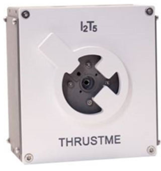
The ThrustMe I2T5 subliming iodine cold gas module, Figure 4.14, was the first iodine propulsion system to be spaceflight tested, flown on the Xiaoxiang 1-08 satellite in 2019 (79) (80). Since then, the system was also launched on RTAF’s NAPA-2 in June 2021 and on Spire’s L3C in January 2023. Additional I2T5 launched on the Robusta-3A satellite in 2024, developed by CSUM, which carries various scientific payloads related to meteorology and technology demonstration (81) (82).
The CubeSat Proximity Operations Demonstration (CPOD) is a mission led by Terra Orbital (83) to demonstrate autonomous on-orbit rendezvous and proximity operations using two identical 3U CubeSats. Each spacecraft incorporates a cold gas propulsion system built by VACCO Industries that provides up to 186 N-s of total impulse. This module uses the self-pressurizing refrigerant R236fa propellant, which is exhausted through a total of eight thrusters distributed in pairs at the four corners of the module. CPOD launched in May 2022 as part of SpaceX’s Transporter-5 mission. The CPOD mission demonstrated rendezvous of the CubeSats with intersatellite distances closing from 997 km to a minimum of 0.36 km. On-orbit limitations on experimentation were attributed to multiple factors as the launch date slipped due to many years of delay, including obsolete hardware, partial failure in the solar panels, and a propulsion system anomaly suspected to be a plenum leak (84) (85).
The Mars Cube One (MarCO) technology demonstration mission consisted of two identical CubeSats that followed the InSight spacecraft to Mars in loose formation in 2018. The MarCO spacecraft performed five trajectory correction maneuvers (TCMs) during the mission to Mars. The TCMs were conducted using an R236fa cold gas propulsion system developed by VACCO Industries, which contains four thrusters for attitude control and another four for TCMs. MarCO-B developed a propulsion system leak, which required constant maintenance. A tank to plenum leak was identified prior to launch, which the mission accepted. However, a second leak through a MarCO-B thruster valve developed during flight. The combination of both leaks resulted in a continuous moment on the MarCO-B spacecraft. The MarCO spacecraft succeeded in their mission to relay telemetry from the InSight lander during its descent to Mars (86) (87) (88) (89).
Near-Earth Asteroid Scout (NEA Scout) was a joint MSFC and JPL mission that had a VACCO cold gas MiPS (R236FA propellant), with six 25-mN thrusters, to assist the main propulsion system, a solar sail. However, after deployment from Artemis I in November 2022, the project team was not able to communicate with the spacecraft (90) (91) (92).
- Summary Table of Devices
See Table 4-5 for the current state-of-the-art cold gas devices applicable to small spacecraft.
Solid Motors
- Technology Description
Solid rocket motors have an oxidizer and fuel mechanical mixture stored in solid form (propellant grain). For small satellites, solid rocket motors may be used for impulsive maneuvers such as orbit insertion or quick deorbiting. They achieve moderate specific impulses and high thrust magnitudes. There are some electrically controlled solid thrusters that operate in the millinewton range that are restartable and have steering capabilities. Solid rocket arrays can be compact and suitable for small buses. Composed of several miniature solid rockets, individual units can be fired alone or together, as needed.
- Key Integration and Operational Considerations
- Usually Single-Burn: In general, solid motors are considered a single-burn event system. To achieve multiple burns, the system must be either electrically restartable (a.k.a. electric solid propellants), or several small units must be matrixed into an array configuration. Because electrically controlled solid propellants (ESPs) are electrically ignited, they are considered safer than traditional solid energetic propellants.
- Thrust Vector Control: Thrust vector control systems can be coupled with existing solid rocket motors to provide controllable high delta-v maneuvering.
- Current & Planned Missions
Northrop Grumman offers the STAR 3 motor, which has a maximum thrust of 2050 N. The STAR 3 motor was used as the Transverse Impulse Rocket System for the Mars Exploration Rover (MER) program and was used in 2004 to reduce the lateral velocity of the MER Spirit lander. The STAR 4G motor was developed and tested by NASA GSFC as an orbit-adjust motor for deploying nanosatellite constellations but was not flown, although it is still offered by Northrop Grumman along with other, higher total impulse motors in the STAR line (93).
The Pacific Scientific Energetic Materials Company (PacSci EMC) Modular Architecture Propulsion System (MAPS) array (Figure 4‑15) has a 10-plus year in-orbit lifespan. The MAPS system provides three-axes capability to control attitude, deorbit, drag makeup, and plane and attitude changes with a delta-v greater than 50 m s-1. The capability of the MAPS “plug-and-play” bolt-on design and clean-burning propellant array is scalable and can be custom-fit for a range of interfaces. MAPS was flown in 2017 aboard PacSciSat, which successfully completed all mission objectives (94) (95).
- Summary Table of Devices
See Table 4-6 for the current state-of-the-art solid motor devices applicable to small spacecraft.
Propellant Management Devices
- Technology Description
While not directly a thrust-producing device, propellant management devices (PMDs) are frequently used in liquid propulsion systems to reliably deliver propellant to thruster units. PMDs are commonly a critical part of in-space liquid propulsion systems that do not use bellows or membrane-type tanks. As small spacecraft look toward more complex propulsion system requirements, PMDs will undoubtedly play an integral role. Historically, small spacecraft have used bellows or membrane tanks to ensure propellant delivery and expulsion. However, there is the potential to incorporate PMD structures into additively manufactured tanks and propulsion systems, permitting more conformal structures to be created and optimized for small spacecraft missions. As such, PMDs are briefly covered here for awareness. A more detailed treatment and explanation can be found in the literature. A comprehensive, up-to-date list of the types of PMDs, as well as missions employing PMDs, is available in Hartwig (96).
- Key Integration and Operational Considerations
The purpose of PMDs is to separate liquid and vapor phases within the propellant storage tank upstream of the thruster and to transfer vapor-free propellant in any gravitational or thermal environment. PMDs have flight heritage with all classical storage systems, have been flown with LMP-103S, have no flight heritage with cryogenic propellants, and have been implemented in electric propulsion systems. Multiple PMDs are often required to meet the demands of a particular mission, whether using storable or cryogenic propellants.
- Current & Planned Missions
The Lunar Flashlight Propulsion System used a PMD sponge and ribbon vane. The sponge was additively manufactured, while the ribbon vane was cut from sheet metal and bent to conform to the required dimensions. Surface tension properties, a necessary parameter for PMD sizing, were determined for the ASCENT propellant by Kent State University, funded and managed by NASA. The design and modelling were a joint effort between MSFC and GRC.
- Summary Table of Devices
No summary table is included for propellant management devices.
- Notable Advances
Northrop Grumman has made advances in the development of SmallSat- and CubeSat-scale diaphragm propellant tanks using materials that are compatible with hydrazine and some green monopropellant fuels (97), and demonstrated the utility of additive manufacturing in producing tank shells.
4.6.2 In-Space Electric Propulsion
In-space electric propulsion (EP) is any in-space propulsion technology wherein a propellant is accelerated through the conversion of electrical energy into kinetic energy. The electrical energy source powering in-space EP is historically solar, therefore these technologies are often referred to as solar electric propulsion (SEP), although other energy sources such as nuclear reactors or beamed energy are conceivable. The energy conversion occurs by one of three mechanisms: electrothermal, electrostatic, or electromagnetic acceleration (132) (133) Each of these technologies is covered herein.
This survey of the state-of-the-art in EP does not attempt to review all known devices but focuses on those that can be commercially procured or devices that appear on a path toward commercial availability. The intent is to aid mission design groups and other in-space propulsion end-users by improving their awareness of the full breadth of potentially procurable EP devices that may meet their mission requirements.
Instead of detailing the complete operating range for each propulsion device, the authors provide only the metrics associated with the nominal operating condition to improve comprehension of the data and make initial device comparisons more straightforward. When a manufacturer does not specifically state a nominal operating condition in the literature, the manufacturer may have been contacted to determine a preferred nominal operating condition; otherwise, a nominal operating condition was assumed based on similarity to other devices. For those metrics not specifically found in published literature, approximations have been made when determinable from the available data. Readers are strongly encouraged to follow the references cited to the literature describing each device’s full performance range and capabilities.
Electrothermal
- Technology Description
Electrothermal technologies use electrical energy to increase the enthalpy of a propellant, whereas chemical technologies rely on exothermal chemical reactions. Once heated, the propellant is accelerated and expelled through a conventional converging-diverging nozzle to convert the acquired energy into kinetic energy, like chemical propulsion systems. The specific impulse achieved with electrothermal devices is typically of similar magnitude to chemical devices given that both electrothermal and chemical devices are fundamentally limited by the working temperature limits of materials. However, electrothermal technologies can achieve a somewhat higher specific impulse than chemical systems since they are not subject to the limits of chemical energy storage.
Electrothermal devices are typically subclassified into one of the following three categories:
- Resistojet devices employ an electrical heater to raise the temperature of a surface that in turn increases the temperature of a gaseous propellant.
- Arcjet devices sustain an electrical arc through an ionized gaseous propellant, resulting in ohmic heating.
- Electrodeless thrusters heat a gaseous propellant through an inductively or capacitively coupled discharge or by radiation.
- Key Integration and Operational Considerations
- Propellant Selection: Electrothermal technologies offer some of the most lenient restrictions on propellant selection for in-space propulsion. Whereas chemical systems require propellants with both the right chemical and physical properties to achieve the desired performance, electrothermal systems primarily depend on acceptable physical properties. For example, electrothermal devices can often employ inert gases or even waste products such as water and carbon dioxide. They also allow use of novel propellants such as high storage density refrigerants or in-situ resources. That said, not all propellants can be electrothermally heated without negative consequences. Thermal decomposition of complex molecules may result in the formation of polymers and other inconvenient byproducts. These byproducts may result in clogging of the propulsion system and/or spacecraft contamination.
- Propellant Storage: Electrothermal devices may require that propellants be maintained at a high plenum pressure to operate efficiently. This may require a high-pressure propellant storage and delivery system.
- High Temperature Materials: The working temperature limit of propellant-wetted surfaces in the thruster head is a key limitation on the performance of electrothermal devices. As such, very high temperature materials, such as tungsten and molybdenum alloys, are often employed to maximize performance. The total mass and shape of these high temperature materials are a safety consideration during spacecraft disposal. While most spacecraft materials burn up on re-entry, the re-entry behavior of devices using these high temperature materials will be scrutinized when assessing the danger of debris to life and property.
- Power Processing: While some simple resistojet devices may operate directly from spacecraft bus power, other electrothermal devices may require a relatively complex power processing unit (PPU). For example, a radio-frequency electrodeless thruster requires circuitry to convert the direct-current bus power to a high-frequency alternating current. In some cases, the cost and integration challenges of the PPU can greatly exceed those of the thruster.
- Thermal Soak-back: Given the high operating temperatures of electrothermal devices, any reliance on the spacecraft for thermal management of the thruster head should be assessed. While the ideal propulsion system would apply no thermal load on the spacecraft, some thermal soak-back to the spacecraft is inevitable, whether through the mounting structure, propellant lines, cable harness, or radiation.
- Missions
The Bradford (formerly Deep Space Industries) Comet water-based electrothermal propulsion system (Figure 4.16) has been implemented by multiple customers operating in low-Earth orbit, including HawkEye 360, Capella Space, and BlackSky Global (134). All missions use the same Comet thruster head, while the BlackSky Global satellites use a larger tank to provide a greater total impulse capability. The HawkEye 360 Pathfinder mission is a constellation of three small microsatellites built by Space Flight Laboratory (SFL) based on its 15-kg NEMO platform; each spacecraft measures 20 x 20 x 44 cm3 with a mass of 13.4 kg (135) (136). The Comet provides each HawkEye 360 pathfinder a total delta-v capability of 96 ms-1. The approximate dimensions of the BlackSky Global spacecraft are 55 x 67 x 86 cm3 with a mass of 56 kg (138).
The Propulsion Unit for CubeSats (PUC) system (139), Figure 4.17, was designed and fabricated by CU Aerospace LLC (Champaign, IL) and VACCO Industries under contract with the U.S. Air Force to supply two government missions (140). The system was acquired for drag makeup capability to extend asset lifetime in low-Earth orbit. The system uses SO2 as a self-pressurizing liquid propellant. The propulsion system electrothermally heats the propellant using a micro-cavity discharge (MCD) and expels the propellant through a single nozzle (141). It can alternatively use R134a or R236fa propellants, but only in cold-gas mode with reduced performance. Eight flight units were delivered to the Air Force in 2014, although it remains unknown if any have flown.
In 2019, CU Aerospace was selected for a NASA STMD Tipping Point award to design, fabricate, integrate, and perform mission operations for the Dual Propulsion Experiment (DUPLEX) 6U CubeSat. DUPLEX has two of CU Aerospace’s micro-propulsion systems onboard: one Monofilament Vaporization Propulsion (MVP) system (142) (143) (144), Figure 4.18, and one Fiber-Fed Pulsed Plasma Thruster (FPPT) system (148) (149) (150) (151) (152), Figure 4.45. The MVP is an electrothermal device that vaporizes and heats an inert solid polymer propellant fiber to 725 K. The coiled solid filament approach for propellant storage and delivery addresses common propellant safety concerns, which often limit the application of propulsion on low-cost CubeSats. In-orbit operations will demonstrate multiple mission capabilities including inclination change, orbit raising and lowering, drag makeup, and deorbit burns. DUPLEX was delivered to the International Space Station on a Cygnus cargo ship in September 2025 (154) (155).
AuroraSat-1 is a technology demonstration 1.5U CubeSat that is demonstrating multiple propulsion devices by Aurora Propulsion Technologies. AuroraSat-1 carries Aurora’s smallest version of Aurora Resistojet Module for Attitude control (ARM-A) (156), Figure 4.19, and a demonstration unit of their Plasma Brake Module (PBM) (157). The ARM-A system integrated into AuroraSat-1 has six resistojet thrusters for full 3-axis attitude control and 70 grams of water propellant, providing a total impulse of 70 N-s. AuroraSat-1 is built by SatRevolution, with Aurora providing the payloads. The satellite was launched by Rocket Lab in May 2022. (158) (159). See section 4.6.3 for discussion of the PBM module.
The OPTIMAL-1 technology demonstration 3U nanosatellite by ArkEdge Space Inc. launched in late 2022 and was deployed from the International Space Station in early 2023. Among other technology demonstration devices, OPTIMAL-1 contains a Pale Blue water resistojet thruster (160).
SPHERE-1 EYE, a 6U CubeSat developed by Sony Group Corporation, includes a Pale Blue Water Resistojet Thruster. The satellite was launched aboard a SpaceX Falcon 9 on January 3rd, 2023, and has been orbiting Earth at an altitude between 500 km to 600 km. The water propulsion system is expected to prolong the satellite’s life by 2.5 years. The propulsion system operated for approximately 2 minutes on March 3rd, 2023, and the company confirmed the successful generation of thrust from flight telemetry (161).
- Summary Table of Devices
See Table 4-7 for current state-of-the-art electrothermal devices applicable to small spacecraft.
Electrosprays
- Technology Description
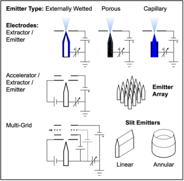
Electrospray propulsion systems generate thrust by electrostatically extracting and accelerating ions or droplets from a low-vapor-pressure, electrically conductive, liquid propellant (Figure 4.20). This technology can generally be classified into the following types according to the propellant used:
Ionic-Liquid Electrosprays: These technologies use ionic liquids (i.e., salts in a liquid phase at room conditions) as propellant. The propellant is stored as a liquid, and onboard heaters may be present to maintain propellant properties within the desired operational temperature range. Commonly used propellants include 1-ethyl-3-methylimidazolium tetrafluoroborate (EMI-BF4) and bis(trifluoromethylsulfonyl)imide (EMI-Im). Thrusters that principally emit droplets are also referred to as colloid thrusters.
Field Emission Electric Propulsion (FEEP): These technologies use low-melting-point metals as propellant. The propellant is typically stored as a solid, and onboard heaters are used to liquefy the propellant prior to thruster operations. Common propellants include indium and gallium.
Feed systems for electrospray technologies can be actively fed via pressurant gas or passively fed via capillary forces. The ion (high-ISP) or droplet (moderate-ISP) emission can be controlled by modulation of the high-voltage (i.e., >1 kV) input in a closed-loop feedback system with current measurements. Stable operations in either emission mode can provide precise impulse bits.
- Key Integration and Operational Considerations
- Charge Balance: Ionic liquid propellants can support electrospray operations with just cation (i.e., positively charged) emission or bi-polar emission (i.e., both anions and cations). For cation-only emission, as with FEEP thrusters, a separate cathode neutralizer is needed to maintain overall charge balance; such neutralizers do not necessarily need to be tightly integrated with the thruster heads. As such, the additional mass, volume, and power impacts must be considered in spacecraft integration. For electrospray technologies using bi-polar emission, reliable high-voltage switching in the power electronics becomes a critical consideration.
- Plume Contamination: Because propellants for electrospray propulsion systems are electrically conductive and condensable as liquids or solids, impingement of the thruster plume on spacecraft surfaces may lead to electrical shorting and surface contamination of solar panels and sensitive spacecraft components. Consideration of only the primary beam plume may not be sufficient, as droplet emission and molecular fragmentation within the plume can generate off-axis species. Plume shields are frequently employed on spacecraft to protect sensitive surfaces in the absence of high-fidelity electrospray plume models or characterization data.
- Propellant Handling and Thruster Contamination: Ionic liquids and metallic propellants can be sensitive to humidity and oxidation, so care is needed if extended storage is required prior to flight. Electrospray technologies can also be sensitive to contamination of the thruster head during propellant loading, ground testing (e.g., backsputter or outgassed materials from the test facility), and handling (i.e., foreign object debris). Precautions should be taken to minimize contamination risks from manufacturing, through test and launch. Post-launch, ionic liquids can outgas (e.g., water vapor) when exposed to the space environment, and such behavior should be accounted for in the mission operations. Due to environmental factors such as spacecraft outgassing and atomic oxygen levels, thruster operations following spacecraft deployment may need a conditioning or burn-in period before achieving full propulsive performance.
- Performance Stability and Lifetime: As an electrospray propulsion system operates over time, the propulsive performance can degrade as the plume impinges upon and deposits condensable propellant on thruster head surfaces; in time, sufficiently deposited propellant buildup can electrically short out the thruster electrodes and terminate thruster operation. Especially for missions with large total impulse requirements, lifetime testing or validated life models of the electrospray propulsion system in a relevant environment are important for understanding end-of-life behavior.
- Specific Impulse: Even for electrosprays that principally emit ions, operational thruster modes and instabilities can result in droplet emission that degrade the specific impulse and thrust efficiency. Caution is advised when considering claimed specific impulse or other propulsive properties (e.g., thrust vector and beam divergence) derived from plume characteristics; verification test data in a relevant environment are important for properly assessing these claims.
- Precision Thrust: Electrospray devices have the potential to provide very precise thrust during continuous operations. For devices that can operate in pulsed mode via pulsed modulation of the high-voltage input, fine impulse bits (i.e., <10 μN-s) may be achievable. Such operations can permit precise control over spacecraft attitude and maneuvering. Verification test data in a relevant environment should be used to properly assess the degree of thrust precision.
- Missions
The ESA Laser Interferometer Space Antenna (LISA) Pathfinder spacecraft was launched in December 2015 on Vega flight VV06. Onboard were two integrated propulsion modules associated with the NASA Space Technology 7 Disturbance Reduction System (ST7 DRS). Each propulsion module contained four independent Busek Colloid MicroNewton Thrusters (CMNT), propellant-less cathode neutralizers, power processing units, digital control electronics, and low-pressure propellant tanks. The propulsion system was successfully commissioned in-orbit in January 2016 after having been fully fueled and stored for almost eight years. The electrospray modules (Figure 4.21) were operated at the Earth-Sun Lagrange Point 1 for 90 days to counteract solar disturbance forces on the spacecraft; seven of the eight thrusters demonstrated performance consistent with ground test results, and the full propulsion system met mission-level performance requirements (163).
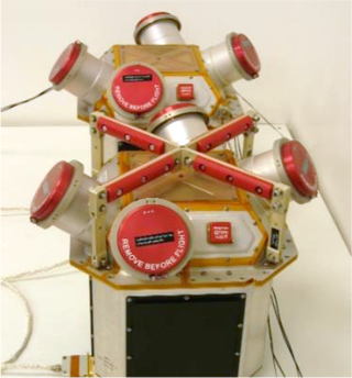
The Enpulsion Nano FEEP (Figure 4.22), formerly the IFM Nano, was first integrated onboard a 3U Planet Labs Flock 3P CubeSat and launched via PSLV-C40 in January 2018. The indium-propellant propulsion system (with integrated thruster head, propellant storage, and power processing unit) was demonstrated in a 491-km by 510-km orbit. Two thruster firing sequences were reported, with the first a 15-minute firing in non-eclipse and the second a 30-minute firing in eclipse. Global Positioning System (GPS) telemetry data onboard the spacecraft indicated good agreement with the ~220 µN commanded thrust (164). Since this initial demonstration, the Enpulsion Nano has flown onboard other spacecraft, but limited on-orbit data is publicly available. These missions include the ICEYE-X2 (launched onboard Falcon-9 flight F9-64 in December 2018) to provide low-Earth orbit interferometric synthetic aperture radar observations (165) (166) aand the DOD-funded Harbinger technology demonstrator (launched onboard Electron flight STP-27RD in May 2019) (167) (168). The Enpulsion Nano was also integrated onboard the Zentrum für Telematik (Würzburg) NetSat formation-flying demonstrator mission, which launched as a Soyuz-2 rideshare in September 2020 (169) (170). A summary of available on-orbit statistics, anomalies, and lessons learned for the Enpulsion Nano family (Nano, Nano R3, and Nano AR3) is available (171).
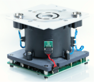
An Enpulsion Micro R3 (Figure 4.23) was housed onboard the GMS-T mission, which launched in January 2021 onboard a Rocket Lab Electron. The telecommunications satellite uses an OHB Sweden Innosat platform with propulsive capability for collision avoidance. Inaugural on-orbit commissioning of the propulsion system was confirmed in March 2021 (173).
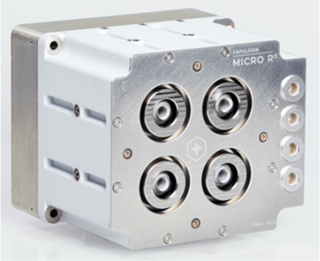
The University Würzburg Experimental Satellite 4 (UWE-4) was launched as a secondary payload onboard the Soyuz Kanopus-V 5 and 6 mission in December 2018. This 1U spacecraft housed two Morpheus Space NanoFEEP systems, with each system consisting of two gallium-propellant thrusters, a power processing unit board for the UNISEC Europe bus, and a propellant-less cathode neutralizer. An experiment using one thruster as an attitude control actuator was reported, with the increased spacecraft rotation rate corresponding to a derived thrust magnitude of ~5 µN; anomalous torque was attributed to unexpected impingement of the thruster plume upon the spacecraft antenna (174) (175). Orbit lowering capability was demonstrated in 2020; of the four individual thrusters, three experienced anomalous behavior during the UWE-4 mission (176). A 3U-Cubsat implementation of the same NanoFEEP technology is shown in Figure 4.24.
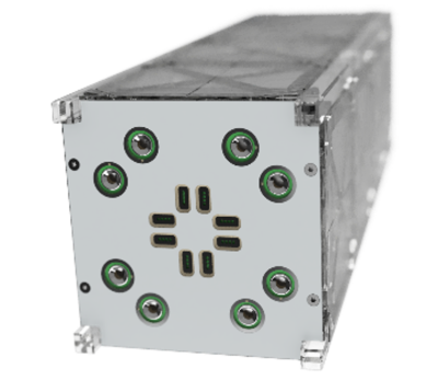
- Summary Table of Devices
See Table 4-8 for current state-of-the-art electrospray devices applicable to small spacecraft.
Gridded-Ion
- Technology Description
Gridded-ion propulsion systems ionize gaseous propellants via a plasma discharge, and the resultant ions are subsequently accelerated via electrostatic grids (i.e., ion optics). This technology can generally be classified according to the type of plasma discharge employed:
- Direct-Current (DC) Discharge: The propellant is ionized via electron bombardment from an internal discharge cathode (Figure 4.25).
- Radio-Frequency (RF) Discharge: No internal discharge cathode is present. Instead, the propellant is ionized via RF or microwave excitation from an RF generator (Figure 4.26).
Gridded-ion thrusters typically operate at high voltages and include an external neutralizer cathode to maintain plume charge neutrality. High specific impulse can be achieved, but the thrust density is fundamentally limited by space-charge effects. While the earliest thruster technologies used metallic propellants (i.e., mercury and cesium), modern gridded-ion thrusters use noble gases (e.g., xenon, krypton) or iodine.
- Key Integration and Operational Considerations
- Performance Prediction: Due to the enclosed region of ion generation and acceleration, gridded ion thrusters tend to be less sensitive to test-facility backpressure effects than other devices such as Hall thrusters. This allows for more reliable prediction of in-flight performance based on ground measurements. Furthermore, the separation between ion generation and acceleration mechanisms within the device tends to make calculations of thrust and ion velocity (or ISP) more straightforward.
- Grid Erosion: Charge-exchange ions formed between and downstream of the ion optics can impinge upon and erode the grids. Over time, this erosion can lead to a variety of failure modes, including grid structural failure, an inability to prevent electrons from back streaming into the discharge chamber, or the generation of an inter-grid electrical short due to the deposition of electrically conductive grid material. Proper grid alignment must be maintained during thruster assembly, transport, launch, and operations to minimize grid erosion. Random vibration tests at the proto-flight level should be conducted to verify the survivability of the ion optics against launch loads. Validated thermal modeling may be needed to assess the impact of grid thermal expansion during operation.
- Foreign Object Debris: The grids are separated by a small gap, typically less than 1 mm, to maximize the electric field and thrust capability of the device. As a result, gridded-ion thrusters tend to be sensitive to foreign object debris, which can bridge the inter-grid gap and cause electrical shorting. Precautions should be taken to minimize such contamination risks from manufacturing, through test, and to launch.
- Cathode Lifetime: Cathodes for plasma discharge or plume neutralization may be sensitive to propellant purity and pre-launch environmental exposure. Feed system cleanliness, bake-out, and use of a high-purity propellant are key factors in maximizing cathode lifetime. The technology provider may recommend maximum cumulative atmospheric exposure and humidity to reduce risk.
- Roll Torque: Misalignments in the ion optics can lead to disturbances in the thrust vector, resulting in a torque around the roll axis that cannot be addressed by the mounting gimbal. For missions requiring extended thruster operations, a secondary propulsion system or reaction wheels may be needed to counter the torque buildup (177).
- Electromagnetic Interactions: For RF-discharge thrusters, electromagnetic interference and compatibility (EMI/EMC) testing may be critical to assess the impact of thruster operations on spacecraft communications and payload functions.
- Power Electronics: Operation of gridded-ion thrusters requires multiple high-voltage power supplies for discharge operation (ion generation), ion acceleration, and neutralization, leading to potentially complex and expensive power electronics.
- Iodine Propellant: To address the volume constraints of small spacecraft, iodine is an interesting propellant. Compared to xenon, iodine’s storage density is three times greater. Furthermore, iodine stores as a solid with low vapor pressure. However, iodine is a strong oxidizer, and the long-duration impact on the thruster and spacecraft remain largely unknown. Recent and upcoming flights will provide insight into potential spacecraft interactions and the long-term reliability of feed system and thruster components exposed to iodine.
- Performance Prediction: Due to the enclosed region of ion generation and acceleration, gridded ion thrusters tend to be less sensitive to test-facility backpressure effects than other devices such as Hall thrusters. This allows for more reliable prediction of in-flight performance based on ground measurements. Furthermore, the separation between ion generation and acceleration mechanisms within the device tends to make calculations of thrust and ion velocity (or ISP) more straightforward.
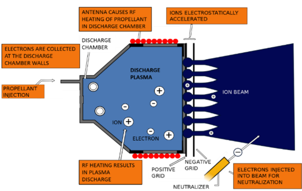
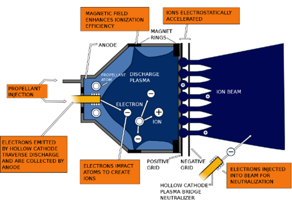
- Missions
The ESA Gravity Field and Steady-State Ocean Circulation Explorer (GOCE) was launched in March 2009 onboard a Rokot / Briz-KM to provide detailed mapping of Earth’s gravitational field and ocean dynamics from an altitude of ~220-260 km. Two QinetiQ T5 DC-discharge gridded-ion thrusters (Figure 4.27), with one serving as a redundant backup, successfully provided drag make-up for the 1000-kg satellite until the xenon propellant was exhausted in October 2013 (178) (179) (180) (181).
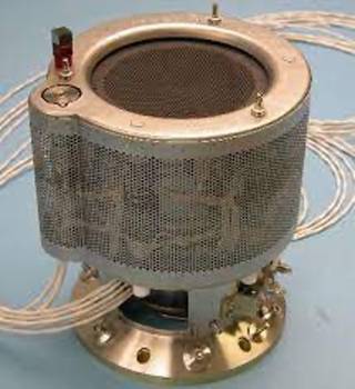
ThrustMe’s NPT30-I2 1U or 1.5U (Figure 4.28), an integrated, RF-discharge gridded-ion propulsion system, has at least two units in space as of July 2023. The Beihangkongshi-1 satellite was launched in November 2020 onboard a Long March 6 rocket. As part of the first on-orbit demonstration of iodine-propellant electric propulsion, two 90-minute burns provided an orbital altitude change of 700 m (182) as described in a Nature publication (183). In April 2023, the 1.5U flew onboard a Space Flight Laboratory of the University of Toronto Institute for Aerospace Studies (UTIAS) 35-kg DEFIANT bus for the Norwegian Space Agency’s NorSat-TD mission (184), which included a demonstration of satellite collision avoidance maneuvers (185). As of July 2023, ThrustMe reported more than 100 systems on order (186) (187).
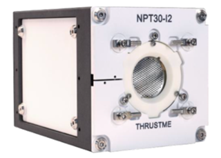
The Lunar IceCube and LunarH-Map missions both included a Busek BIT-3 propulsion system (Figure 4.29) with solid iodine propellant. The BIT-3 system was the primary propulsion for each spacecraft’s lunar transfer, orbit capture, orbit lowering, and spacecraft disposal. Each integrated BIT-3 system includes a low-pressure propellant tank with heated propellant-feed system components, a power processing unit to control the RF thruster and RF cathode, and a two-axis gimbal assembly.
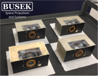
The Lunar IceCube mission, led by Morehead State University, aimed to characterize the distribution of water and other volatiles on the Moon from a highly inclined lunar orbit with a perilune less than 100 km. The 6U spacecraft was launched as a secondary payload onboard Artemis I (188) (189). Communication issues with the CubeSat were reported shortly after launch (190).
The Lunar Polar Hydrogen Mapper (LunaH-Map) mission, led by Arizona State University, aimed to map hydrogen distributions at the lunar south pole from a lunar orbit with a perilune less than 20 km. The 6U spacecraft was launched as a secondary payload onboard Artemis I (191). The mission ended in late 2023 as the BIT-3 was inoperable and unable to perform the required mission maneuvers. The mission team concluded that the propulsion system’s tank valve was stuck closed (192) (193). As of April 2026, Busek indicates that several BIT-3 systems are operational in commercial missions, although mission details have not been publicly disclosed.
- Summary Table of Devices
See Table 4-9 for current state-of-the-art gridded-ion devices applicable to small spacecraft.
Hall-Effect
- Technology Description
The Hall-effect thruster (HET) is arguably the most successful in-space EP technology by quantity of units flown. The Soviet Union first flew a pair of EDB Fakel SPT-60 HETs on the Meteor-1-10 spacecraft in 1971. Between 1971 and 2018, over 300 additional HETs flew internationally, although EDB Fakel produced the vast majority. The first flight of a non-Russian HET was on board the European Space Agency (ESA) Small Missions for Advanced Research in Technology (SMART-1) spacecraft in 2003. SMART-1 employed the French PPS-1350 HET, produced by Safran (194). The first flight of a U.S. manufactured HET, the Busek BHT-200, was onboard the TacSat-2 spacecraft (195), a U.S. Air Force Research Laboratory (AFRL) experimental satellite in 2006. In 2010, Aerojet, another U.S. entity, began commercially delivering their 4.5 kW XR5 HET (196), formerly BPT-4000. Launches of HETs greatly accelerated in 2019 with the launch of 120 SpaceX Starlink and 6 OneWeb spacecraft (197), each using an HET. As of April 2026, SpaceX has launched over 11,500 Starlink satellites, and OneWeb has launched over 650 satellites. Suffice to say that HETs have become a mainstream in-space propulsion technology.
The rapid growth in demand for HETs can be attributed to their simple design, historically well-demonstrated reliability, good efficiency, high specific impulse, and high thrust-to-power ratio. Although gridded-ion thrusters (GIT) can achieve a higher specific impulse than HETs, HETs can achieve higher thrust-to-power ratios because HETs have a higher density quasi-neutral plasma, which is not subject to space-charge limitations. The HETs’ higher thrust-to-power ratio will typically shorten spacecraft transit time. On the other end of the spectrum, arcjets provide significantly higher thrust than HETs, however material limitations prevent arcjets from matching the HETs’ electrical efficiency and specific impulse. For many missions, HETs provide a good balance of specific impulse, thrust, cost, and reliability.
HETs are a form of ion propulsion, ionizing and electrostatically accelerating the propellant. Historically, HETs flown in space have relied on xenon propellant, given its high molecular weight, low ionization energy, and ease of handling. One recent exception is the SpaceX Starlink spacecraft using krypton propellant. While HETs typically operate less efficiently with krypton propellant, and krypton has more challenging storage requirements, krypton gas is considerably lower in cost than xenon gas. Lower cost is a compelling attribute, especially when the number of spacecraft are in the thousands, as with the Starlink constellation. While xenon is generally a superior propellant, krypton-fed Hall thrusters will likely become more common. SpaceX’s 2nd Generation Starlink spacecraft made another first using argon as a Hall thruster propellant. While argon has been commonly tested with laboratory HETs due to its low cost and good availability, argon is not generally considered a good choice for spaceflight due to its challenging storage requirements. However, given SpaceX’s need for such large volumes of propellant for thousands of satellites, overcoming supply chain limitations provides a justification for this generally non-ideal propellant. Many other propellants have been considered and ground tested for Hall-effect thrusters, but to date Hall-effect thrusters have flown using primarily xenon, krypton, or argon.
As schematically shown in Figure 4.30, HETs apply a strong axial electric field and radial magnetic field near the discharge chamber exit plane. The ExB force greatly slows the mean axial velocity of electrons and results in an azimuthal electron current many times greater than the beam current. This azimuthal current provides the means by which the incoming neutral propellant is collisionally ionized. These ions are electrostatically accelerated and only weakly affected by the magnetic field. The electron source is a low-work-function material typically housed in a refractory metal structure (i.e., hollow cathode), historically located external to the HET body. Many recent thruster designs have begun centrally mounting the cathode in the HET body as shown in Figure 4.30. The cathode feeds electrons to the HET plasma and neutralizes the plasma plume ejected from the thruster. The high voltage annular anode sits at the rear of the discharge chamber and typically functions as the propellant distribution manifold.
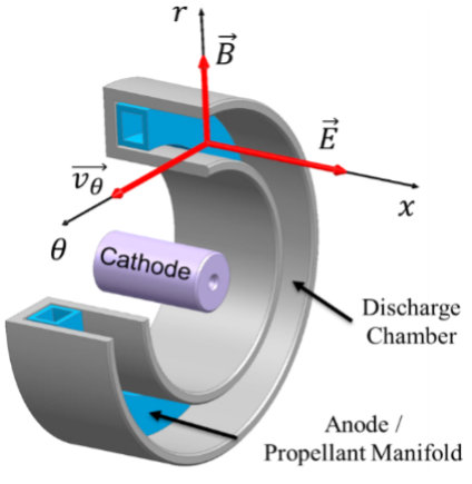
- Key Integration and Operational Considerations
- Ground Facility Effects: Ground facility effects may result in inconsistencies between ground and flight performance. The significance of the inconsistencies depends on factors such as test facility scale, pumping speed, intrusiveness of diagnostics, and thruster electrical configuration.
- Contamination: Plume ions of an HET can affect spacecraft surfaces by erosion or contamination, even at large plume angles. Ground facility measurement of ion density at large angles may underpredict flight conditions.
- Thermal Soak-Back: HET core temperature may exceed 400°C with the cathode exceeding 1000°C. Most HET waste heat radiates directly from the HET surfaces. However, some thermal soak-back to the spacecraft will occur through the mounting structure, propellant feed lines, electrical harness, and radiation.
- Survival Heaters: Given the thermal isolation between the HET and spacecraft, the HET may require a survival heater depending on the qualification temperature and flight environments.
- Performance: HET performance may vary over the life of the device due to erosion and contamination of the plasma wetted HET surfaces. Magnetically shielded thrusters demonstrate less time dependence in performance than classical HETs.
- Thruster Lifetime: Classical HETs are primarily life-limited by erosion of the discharge chamber wall. Magnetically shielded HETs are primarily life-limited by erosion of the front pole covers.
- Cathode Lifetime: Cathode lifetime may be sensitive to propellant purity and pre-launch environmental exposure. Feed system cleanliness, bake-out, and use of a high-purity propellant are key factors in maximizing cathode lifetime. The HET manufacturer may recommend a maximum cumulative atmospheric exposure and humidity. Some cathode emitter formulations are less sensitive to propellant impurities and atmospheric exposure, but these formulations may require other trades such as a higher operating temperature.
- Roll Torque: The ExB force results in a slight swirl torque. For missions requiring extended thruster operations, a secondary propulsion system or reaction wheels may be needed to counter the torque buildup. The roll torque may largely be countered by periodically reversing the direction of the magnetic field. Field reversal requires switching the polarity of the current to the magnet coils. Field reversal is only possible with HETs using electromagnets.
- Thrust Vector: Non-uniformity of the azimuthal plasma, magnetic field, or propellant flow may result in slight variations of the thrust vector relative to the HET physical centerline. Temperature variation of the HET, such as during startup, may result in a slight drifting of the thrust vector.
- Heaterless Cathodes: Heaterless cathode technologies continue to mature. The benefit of a heaterless cathode is elimination of the cathode heater, typically an expensive component due to rigorous manufacturing and acceptance processes. However, the physics of heaterless cathode life-limiting processes requires further understanding. Nevertheless, heaterless cathode demonstrations have empirically shown significant promise. Heaterless cathode requirements on the EP system differ from an HET with a cathode heater. Impacts on the power processing unit and feed system should be well understood when trading a heaterless versus heated cathode.
- Throttling Range: HETs typically throttle stably over a wide range of power and discharge voltage. This makes an HET attractive for missions requiring multiple throttle set-points. However, an HET operates most efficiently at specific throttle conditions. Operating at off-nominal conditions may result in decreased specific impulse and/or electrical efficiency.
- Missions
Canopus-V (or Kanopus-V) is a Russian Space Agency spacecraft for Earth observation with a design life of 5 years. The 450 kg spacecraft launched in 2012 employed a pair of EDB Fakel SPT-50 thrusters. Similarly, the Canopus-V-IK (Kanopus-V-IK) launched in 2017 with a pair of SPT-50 thrusters. The SPT-50 thrusters have a long history of spaceflight dating back to the late 1970s. Although the Canopus bus exceeds 450 kg, the power class and physical scale of the SPT-50 are appropriate for smaller spacecraft. The SPT-50 is nominally a 220 W thruster operated on xenon propellant (198) (199) (200).
The KazSat-1 and KazSat-2 spacecraft produced by Khrunichev Space Center in cooperation with Thales Alenia Space launched in 2006 and 2011, respectively. The KazSat spacecraft are geosynchronous communication satellites. These spacecraft employ the EDB Fakel SPT-70BR thruster. The SPT-70BR is Fakel’s latest version of the SPT-70 product line. EDB Fakel optimized the SPT-70 for operation between 600 and 700 W, but no more than 900 W. Experiments demonstrate a lifetime of 3,100 hours, equating to about 450 kNs. The SPT-70 thrusters have a long history of spaceflight dating back to the early 1980s. Control of KazSat-1 was lost in 2008 (201) (202).
The Busek BHT-200 (Figure 4.31) has the distinction of being the first U.S.-made HET to operate in space. The BHT-200 has flight heritage from demonstrations on the TacSat-2 mission launched in 2006, FalconSat-5 mission launched in 2010, and FalconSat-6 mission launched in 2018. A Busek PPU powered the 200 W HET for each of the FalconSat missions (203) (204) (205). Ground testing of the BHT-200 includes multiple propellants, although all spaceflights of the BHT-200 have used xenon. Busek developed an iodine compatible derivative of the BHT-200 for the NASA iSat mission. It was determined during the course of the iSat project that additional development related to iodine compatible cathodes was required before conducting an in-space demonstration of the technology (206) (207).
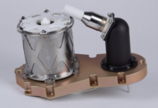
The Israel Space Agency and the French National Center for Space Studies (CNES) jointly developed the Vegetation and Environment monitoring on a New Microsatellite (VENuS) spacecraft launched in 2017. The 268 kg VENuS spacecraft includes a pair of Rafael IHET-300 thrusters (Figure 4.32) and 16 kg of xenon propellant. In-flight operations have demonstrated operation between 250 and 600 W. Rafael developed the IHET-300, nominally operating at 300 W, specifically for small spacecraft (208) (209) (210) (211) (212).
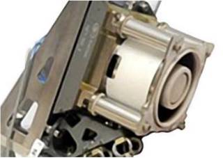
The European and Italian space agencies selected the SITAEL HT100 (Figure 4.33) for an in-orbit validation program to evaluate the device’s capabilities for orbital maintenance and accelerated reentry of a small spacecraft. The uHETSat mission is the first in-orbit demonstration of the HT100. The mission uses the thruster to raise and lower its orbit over a series of verification tests conducted during a planned two-year lifespan. The mission seeks to conduct at least one thousand ignition cycles. The HT100 is nominally a 175 W device operating on xenon propellant. The uHETSat uses the SITAEL S-75 microsatellite platform that is 75 kg with dimensions of 60 x 40 x 36 cm3. The spacecraft launched on December 1, 2023 (213) (214) (215) (216). The HT100 is also baselined for the Italian Space Agency Platino-1 and Platino-2 spacecraft (217).
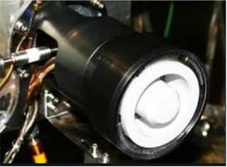
The Astra Spacecraft Engine (ASE), Figure 4.34, successfully achieved orbital ignition onboard the Spaceflight Sherpa-LTE1 orbital transfer vehicle, which launched on SpaceX’s Transporter-2 mission on June 30, 2021 (218). This single-string system is sized to achieve a controlled de-orbit of Sherpa-LTE1 (219). On-orbit performance was demonstrated by operating the system for 5-minute durations. The first 54 maneuvers have been reported (220). After outgassing, performance metrics were nominal within one standard deviation of ground test data. On-orbit thrust averaged 22.4 mN, and specific impulse for each 5-minute thrust maneuver averaged 1108 seconds. Total propulsion system power processing efficiency averaged 94%, including feed system power, circuit efficiency, and housekeeping loads (221). As of November 2023, the ASE aboard the Sherpa-LTE1 had operated for more than 800 five-minute maneuvers (i.e., accumulated total duration of ~70 hours) (218). On July 7, 2024, Sherpa-LTE1 safely deorbited (222). The ASE is designed for operation with xenon and krypton propellants and sized to fit ESPA-class missions. The propulsion system includes several key technologies, including permanent magnets, a heatless instant start cathode, and a radiation hardened PPU. Astra has also reportedly sold ASE units to LeoStella (223), Apex (224), and Astroscale (225). As of March 2023, Astra had reported nine ASE units in orbit (224).
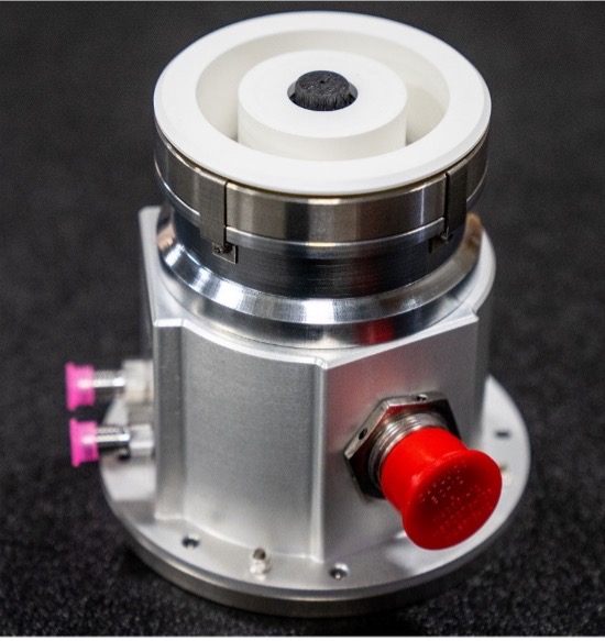
Exotrail’s first in-orbit propulsion demonstration was in November 2020. NanoAvionics and Exotrail partnered to integrate Exotrail’s spaceware-nano (Figure 4.35) into a NanoAvionics M6P nanosatellite 6U bus, which was built, integrated, and qualified in 10 months. Following this, Exotrail signed a contract with AAC Clyde Space to provide propulsion for the Eutelsat ELO 3 (2022) and ELO4 (2023) 6U CubeSats (226) (227) (228) (229) (230), and a contract with Aerospace Lab to provide its spaceware-nano for Aerospace Lab’s Risk Reduction Flight (RRF) mission. The Aerospace Lab spacecraft, known as “Arthur,” was launched in 2021 (231) (232). Blue Canyon Technologies (BCT) selected the Exotrail’s spaceware system for its Venus-class microsatellite platform, which will be used for the NASA’s INCUS mission, which is expected to launch in 2027 (233) (234).
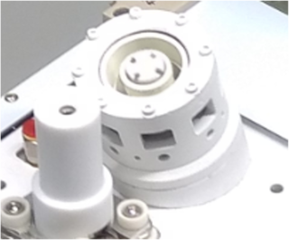
A spaceware-micro (Figure 4.36) was reported to be integrated onboard a York Space Systems S-Class platform for a satellite mission scheduled for launch in late 2023, aiming to orbit the Moon and deliver Earth-to-Moon telecommunication services in support of Intuitive Machines’ lunar south pole mission (235). Exotrail also has agreements to provide the spaceware-micro for missions by OHB Luxspace (236), Satrec Initiative (237), Astro Digital (238), and Muon Space (239).
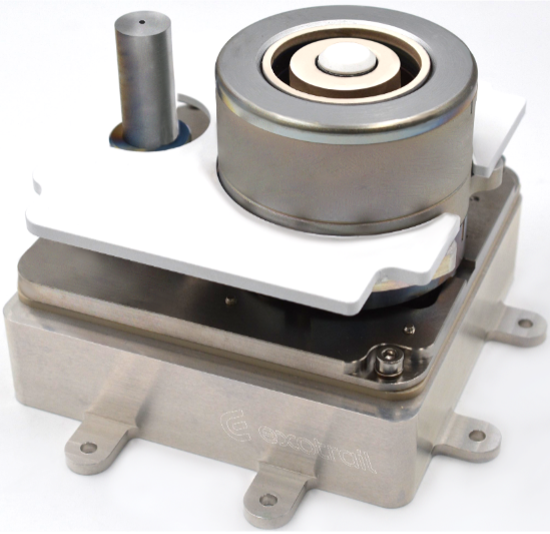
Exotrail launched its spacevan In-Orbit Demonstration (IOD) mission in November 2023. The spacevan uses Exotrail’s spaceware-micro to demonstrate its capabilities (e.g., plane change and altitude change) (240) (241).
Airbus will integrate Exotrail’s spaceware – mini thruster, Exotrail’s 300W–600W class electric propulsion system, onto Airbus’ Earth Observation satellite platform portfolio. Exotrail anticipated completion of the thruster’s qualification activities in 2024 (242).
Blue Canyon, a Raytheon subsidiary, produced satellites for the DARPA Blackjack program. Blue Canyon selected ExoTerra’s Halo thruster (Figure 4.37), for its Phase 2 and Phase 3 satellites (243). ExoTerra has demonstrated Halo on three Blackjack satellites that launched in June 2023 on the SpaceX Transporter-8 rideshare. These are the first flights of ExoTerra’s Halo electric propulsion system (244). Additionally, ExoTerra received a NASA Tipping Point award to perform an in-orbit demonstration of their 12U Courier SEP spacecraft bus. The bus includes ExoTerra’s Halo thruster, xenon flow control system (XFC), power processing unit (PPU), and deployable solar arrays. The Courier spacecraft provides up to 1 km/s of delta-v, while hosting a 2U, 4 kg payload. The Tipping Point mission objective is to demonstrate the SEP system by spiraling to 800 km from a drop-off orbit of 400 km and then deorbiting. Primary mission objectives include demonstration of the solar array deployment and power generation, PPU efficiency, and 2 kg of thruster propellant throughput. For the Tipping Point mission, the 0.85 kg, 1/3U thruster will nominally operate at 135 W discharge power and produce ~8 mN of thrust (245) (246) (247) (248) (249).
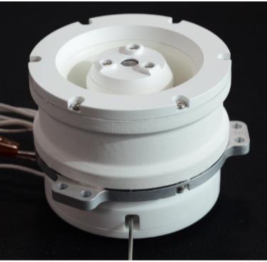
ExoTerra reported in May 2025 delivering 21 Halo propulsion modules to York Space Systems for the Space Development Agency (SDA) Transport Layer (250). ExoTerra was acquired by Voyager Technologies in late 2025 (251).
ExoTerra Resource is commercializing as Halo12 (Figure 4.38) a version of JPL’s Magnetically Shielded Miniature (MaSMi) Hall thruster technology for multiple unnamed flight opportunities. JPL performed extensive development of the technology between 2011 and 2021, culminating in a 7,205-hour wear test of JPL’s engineering model thruster. The life test processed over 100 kg of xenon propellant and produced a total impulse of approximately 1.55 MN-s. Exoterra’s unnamed flight programs (252) require additional life time, beyond JPL’s demonstration, so the same JPL engineering model thruster was recently installed in JPL’s high-bay vacuum facility to extend the demonstration to 8187 hours and 1.73 MN-s. Other qualification tests conducted by JPL include a 25,000 ignition cycle heaterless cathode demonstration, a 3000-cycle coil TVAC test, and dynamic testing of the thruster (253). It is important to note that the thruster tested by JPL was not produced by Exoterra. However, given that the JPL produced thruster continues to be operated in support of Exoterra’s commercialization activities, it is plausable that Exoterra has retained the key life limiting features of the JPL design (252) (254).
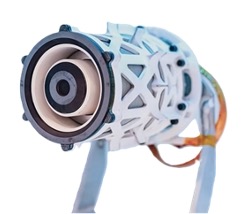
Orbion’s Aurora Hall-effect thruster system (Figure 4.39) is flying on Capella Space’s synthetic aperture radar satellites (255), and will fly on a U.S. Space Force weather satellite under contract with General Atomics Electromagnetic Systems (GA-EMS) (256). Orbion also delivered 33 Aurora propulsion modules to York Space Systems for a military constellation (257). The Aurora propulsion system consists of the Hall-effect thruster and cathode, power processing unit, propellant flow system, and cable harnessing. The system is used for orbit raising, orbit maintenance, and de-orbit. In ground qualification testing, Aurora has demonstrated 400 kN-s total impulse (258). In 2026, Orbion became a wholly owned U.S. subsidiary of York Space (259).
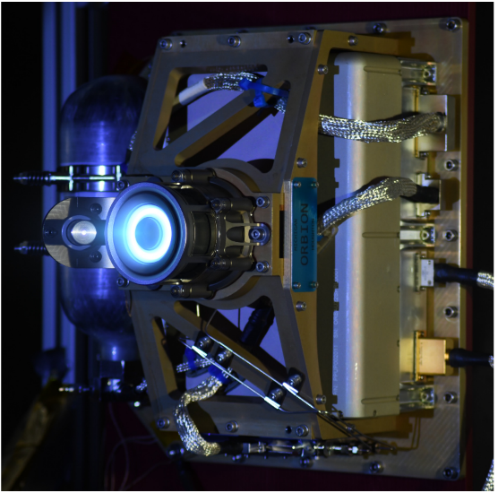
Busek has supplied its BHT-350, Figure 4.40, Hall-effect thruster to Airbus OneWeb Satellites (AOS) for a range of missions. Busek engineered and qualified the thrusters for orbit raising, orbit maintenance, and end-of-life de-orbit. Eighty OneWeb satellites with BHT-350s launched in December 2022 and January 2023. More than 100 units were operating on OneWeb satellites as of August 2023 with all thrusters reported as operational (260) (261) (262) (263).
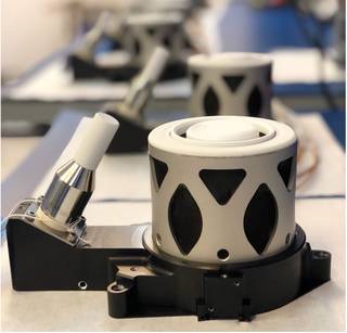
Busek shipped its first flight BHT-600 Hall-effect thruster system to a U.S. Government customer in early 2021. The BHT-600 previously demonstrated a 7,000-hour ground test performed at NASA GRC as part of a NASA Announcement for Collaborative Opportunity (ACO) Space Act Agreement (SAA), Figure 4.41. The thruster successfully demonstrated 70 kilograms of xenon propellant throughput before the ground test was terminated (264) (265).
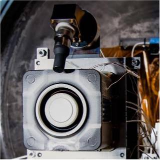
Northrop Grumman’s (NG) Space Systems Sector has developed the NGHT-1X (Figure 4.42) thruster for its next generation satellite servicing vehicle known as the Mission Extension Pod (MEP). MEP carries power and propulsion for self-propelled orbit raising as well as station keeping and momentum management when docked to a client vehicle. MEP is designed for a 6-year mission life but can carry a propellant load that permits even longer lifetimes. The thruster is designed to generate a minimum total impulse of 2.1 MN-s, not including margin, to enable the MEP mission. NG partnered with the NASA Glenn Research Center (GRC) to develop the NGHT-1X, licensing NASA’s technology for a high propellant throughput, sub-kilowatt Hall-effect thruster. NG’s SpaceLogistics has sold all three MEPs that are on the manifest for the first launch on a Falcon 9 rocket planned for 2026 (266) (267) (268) (269) (270) (271) (272).
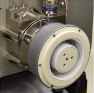
The EOS SAT-1 developed by Dragonfly Aerospace for the EOS Data Analytics space mission successfully tested its SETS SPS-25 propulsion system. The EOS SAT-1 launched on a Falcon 9 rocket on January 3, 2023 (273) (274).
The Aliena Pte Ltd MUSIC-SI Hall thruster (Figure 4.43) was integrated on the NuX-1 3U nanosatellite in July 2021. In-orbit deployment was achieved in January 2022 during SpaceX Transport 3 Mission. Aliena’s Hall thruster became the first to operate on board such a small satellite, featuring the lowest power consumption for a commercial Hall thruster at 20W (275) (276) (277) (278) (279).
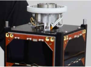
The MUSIC-HM Hall thruster from Aliena and four ARM-A resistojets from Aurora Propulsion Technologies form the Multi-modal Electric Propulsion Engine (MEPE). MEPE was deployed on an Orbital Astronautics 12U satellite (ORB-12 Strider) in July 2023 by a PSLV rocket (PSLV C-56 DS-SAR mission). The mission will demonstrate the capability of these propulsion systems to support a small satellite constellation. MEPE’s dual electric propulsion technologies allow both the high thrust, low specific impulse of resistojets and low thrust, high specific impulse of Hall thrusters. Both systems share a common propellant, electronics, and fluidics (275) (279) (280).
- Summary Table of Devices
See Table 4-10 for current state-of-the-art HET devices applicable to small spacecraft.
Pulsed Plasma and Vacuum Arc Thrusters
- Technology Description
Pulsed Plasma Thrusters (PPT) produce thrust by triggering an electric arc between a pair of electrodes that typically ablates a solid-state propellant like polytetrafluoroethylene (PTFE) or ionizes a gaseous propellant. The plasma may be accelerated by either electrothermal or electromagnetic forces. Whether the mechanism of acceleration is electrothermal, electromagnetic, or often some combination thereof, is determined by the device topology (281).
Electrothermal PPTs characteristically include a chamber formed by a pair of electrodes and solid propellant, wherein propellant ablation and heating occur. During and immediately following each electric discharge, pressure accumulates and accelerates the propellant through a single opening. Electromagnetic PPTs characteristically do not highly confine the propellant as plasma forms. The current pulse, which may exceed tens of thousands of amps, highly ionizes the ablated material or gas. The current pulse further establishes a magnetic field, where the jxB force accelerates the plasma. PPT devices that are predominantly electrothermal typically offer higher thrust, while devices that are predominantly electromagnetic offer higher specific impulse.
The simplest PPTs have no moving parts, which may provide a high degree of reliability. However, as the solid propellant is consumed, the profile of the propellant surfaces constantly change. Thus, PPTs with static solid propellant demonstrate a change in performance over their life and inherently have a relatively limited lifetime. More complex solid propellant PPTs include a propellant feed mechanism. Typically, the propellant surface profile changes during an initial burn-in period but then settles into a steady-state behavior where the propellant advancement is balanced by the propellant ablation.
PPT devices are suitable for attitude control and precision pointing applications. PPTs offer small and repeatable impulse bits, which allow for very high precision maneuvering. The complete propulsion system consists of a thruster, an ignitor, and a power processing unit (PPU). Energy to form the pulsed discharge is stored in a high voltage capacitor bank, which often accounts for a significant portion of the system mass. Once the capacitors are charged, resulting in a large differential voltage between the electrodes, the ignitor provides seed material that allows the discharge between the electrodes to form. Various materials and gases (including water vapor) have been tested with PPTs; however, PTFE remains most common.
Vacuum arc thrusters (VAT) are another type of pulsed plasma propulsion (282). This technology consists of two metallic electrodes separated by a dielectric insulator. Unlike PPTs, one VAT electrode is sacrificial, providing the propellant source. The mechanism for propellant acceleration is predominantly electromagnetic, resulting in a characteristically high specific impulse and low thrust. One variant of the VAT is predominantly electrostatic, through the inclusion of a downstream electrostatic grid.
- Key Integration and Operational Considerations
- Safety: PPT capacitor banks often store tens of joules of energy at potentially a couple thousand volts. Follow good electrical safety practices when operating and storing PPTs in a laboratory environment.
- Input Power Range: PPTs and VATs are pulsed devices, which operate by discharging energy stored in capacitors with each pulse. Thus, the propulsion system’s average power draw from the spacecraft bus can be quite low or high depending on capacitor energy storage and pulse frequency. This flexibility allows PPTs to be applied to spacecraft with limited power budgets of just a few watts, or ample power budgets of hundreds of watts.
- Minimum Impulse Bit: A compelling capability of pulsed devices is the ability to generate small, precise, and well-timed impulse bits for precise spacecraft maneuvering. By controlling the discharge voltage, very small impulse bits on the order of micronewton-seconds are easily achieved.
- Compact and Simple Designs: PPTs and VATs are typically very simple and compact devices. While the total impulse capability is small compared to other forms of EP, these devices offer a particularly attractive solution for CubeSats, where low cost may be a more significant consideration than total impulse. The systems are also attractive for learning environments where propulsion expertise such as high-pressure feed systems and propellant management may be lacking.
- Late-Time Ablation: Although pulsed devices allow for operation over a wide range of pulse frequency, thruster efficiency typically improves with higher pulse rate. Late-time ablation is a key inefficiency of solid propellant pulsed devices, where material continues to ablate from the propellant surface well after the discharge pulse. The amount of material accelerated may be maximized through higher frequency pulsing.
- Thrust-to-Power: Pulsed devices suffer from several inefficiencies including late time ablation, frozen flow, and wall heating. Propulsion system efficiency is typically below 20%, and may be as low as a few percent. Thus, although pulsed devices may have high specific impulse, the thrust-to-power is low. Small spacecraft with limited power for propulsion may find that large propellant loads provide little benefit as there is inherently a limitation to the number of pulses achievable over the life of the power-limited spacecraft.
- Thermal Soak-back: The low thruster efficiencies may result in large thermal loads on the spacecraft due to thermal soak-back, especially at high rates of pulsing. The spacecraft’s ability to radiate this energy to limit heating may set an upper bound on the pulse frequency.
- Ignitor: Pulsed devices usually require some form of ignitor to provide seed material to lower the impedance between the electrodes and initiate the discharge pulse. As such, the lifetime of the ignitor may drive the lifetime of the thruster. Ignitors may fail due to erosion or fouling that prevents sparking. Some devices may include multiple redundant ignitors to increase system lifetime.
- Shorting: The electrodes of pulsed devices are separated by isolating elements. Shadow shielding or other physical features are typically necessary to avoid shorting between electrodes as conductive material ejected by the thruster accumulates. While PTFE is an insulator, the PTFE is reduced to carbon and fluorine when ablated, where carbon accumulation provides a potentially conductive path. VATs employ metal propellants that can similarly result in unintended shorting.
- Spacecraft Contamination: As with any conductive propellant, spacecraft contamination is a concern. Plume interaction with the spacecraft must be understood to assess the impact of the plume on the operation of critical surfaces such as solar panels, antennas, and radiators.
- Missions
In 2019, CU Aerospace was selected for a NASA STMD Tipping Point award to design, fabricate, integrate, and perform mission operations for the DUPLEX 6U CubeSat having two of CU Aerospace’s micro-propulsion systems onboard, one Monofilament Vaporization Propulsion (MVP) system (142) (143) (144), shown in Figure 4.18, and one Fiber-Fed Pulsed Plasma Thruster (FPPT) system (148) (149) (150) (151) (152), shown in Figure 4.45. The FPPT can provide a large total impulse primary propulsion for micro-satellites through implementation of a novel PTFE fiber propellant storage and delivery mechanism. A major enhancement of the FPPT technology over classical PPTs is the ability to control both the propellant feed rate and pulse energy, thereby providing control of both the specific impulse and thrust. The FPPT can also provide precision control capability for small spacecraft requiring capabilities such as precision pointing or formation flying. Thrust-vectoring capability of ±10° in the yaw and pitch axes (also with the potential for roll control authority) has been incorporated into the system, allowing for limited ACS capability and wheel desaturation for deep space missions. In-orbit operations will demonstrate multiple mission capabilities including inclination change, orbit raising and lowering, drag makeup, and deorbit burns. DUPLEX was delivered to the International Space Station on a Cygnus cargo ship in September 2025 (154) (155).
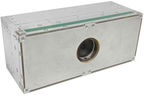
The Benchmark Space Systems’ Xantus thruster (Figure 4.44) is a millinewton-class non-toxic metal plasma thruster that is compatible with multiple solid metal propellants (283). The baseline molybdenum propellant has a measured specific impulse of 1774 seconds. The Xantus thruster first launched in January 2023 on board the USSF Rapid Revisit Optical Cloud Imager (RROCI) 12U CubeSat demonstration mission. However, the RROCI spacecraft failed to deploy after launch. Xantus was successfully deployed on board an Orion Space Solutions’ 12U CubeSat in low-Earth orbit in March 2024 (284) (285).
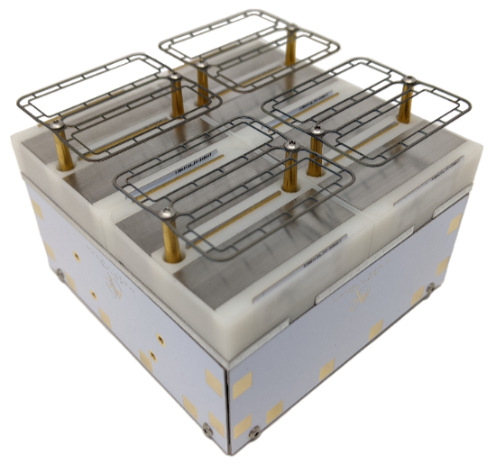
Comat’s Plasma Jet Pack (PJP) vacuum arc thruster can be configured with up to four nozzles operating on a solid/inert propellant to provide vectorized thrust (286). The PJP has launched as part of the Vega VV23 mission on the ∑yndeo-2 6U CubeSat. At the time of this publication, no details have yet been reported on the commissioning of the propulsion system (287).
The Neumann Drive is a center-triggered pulsed cathodic arc propulsion technology developed by Neumann Space using molybdenum propellant. The Neumann Drive is offered in multiple configurations offering a range of propulsive performance depending on available spacecraft power (288). The ND-15 thruster, designed for nanosatellites, was demonstrated on Australia’s Skykraft satellite (289) (290) (291), and another ND-15 was flown in late 2023 on the University of Melbourne’s SpIRIT nanosatellite (292) (295). The ND-50, a more compact system, was deployed in January 2025 on the 6U EDISON satellite (296) and in January 2026 on the 150 kg CarbSAR satellite (297) (298).
- Summary Table of Devices
See Table 4-11 for current state-of-the-art pulsed plasma and vacuum arc devices applicable to small spacecraft.
Ambipolar
- Technology Description
Ambipolar thrusters ionize gaseous propellant within a discharge cavity via various means, including DC breakdown or RF excitation. The escape of high-mobility electrons from the discharge cavity creates a charge imbalance in the plasma discharge, and the subsequent ambipolar diffusion accelerates ions out of the cavity to generate thrust.
Because the thruster plume is charge-neutral, no neutralizer assembly is necessary. A variety of propellants are theoretically usable due to the absence of exposed electrodes (and their associated material compatibility concerns).
- Key Integration and Operational Considerations
- Propellant Agnostic: While ambipolar thrusters may be operable on a variety of propellants thanks to the devices’ lack of exposed electrodes, different propellants will have different ionization costs (i.e., impact on thruster efficiency), plume behavior, and propellant storage requirements that should be considered during propellant selection.
- Electromagnetic Interactions: For RF-discharge thrusters, electromagnetic interference and compatibility (EMI/EMC) testing may be critical to assess the impact of thruster operations on spacecraft communications and payload functionality.
- Thermal Soak-back: Low thruster efficiencies may result in large thermal loads on the spacecraft due to thermal soak-back. Validated thermal modeling should be considered to assess impacts to the host spacecraft.
- Missions
The SpaceX Falcon 9 Transporter-1 launch in January 2021 included two small satellites with the Phase Four Maxwell Block 1 onboard. This integrated propulsion system (Figure 4.46) includes the RF thruster and power electronics along with a xenon propellant tank and feed system (299). Phase Four has further reported in 2023 that its Maxwell Block 2, with improved modularity and performance compared to Block 1, has been demonstrated on orbit (300).
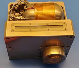
The UniSat-7 mission, led by GAUSS, is a 36-kg microsatellite that launched via Soyuz-2-1a Fregat in March 2021. This technology demonstration mission included a T4i iodine-propellant REGULUS (50-I2-Small) module (Figure 4.47), an integrated propulsion system that includes thruster, power processing unit, and heated propellant-feed components. The propulsion demonstration is expected to include orbit raising and lowering around the 600-km orbit (302) (303) (304).
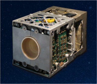
A 6U CubeSat from Team Miles was awarded a rideshare slot onboard Artemis I, as one of the winning teams in NASA’s Cube Quest Challenge. The objective of the mission was to demonstrate deep space communications from beyond a 2.5-million mile range. Twelve ConstantQ water-propellant thrusters (Figure 4.48), an earlier version of Team Miles’ current M1.4 system, were integrated onboard the CubeSat to provide primary propulsion as well as 3-axis control (305) (306). While the spacecraft was deployed in November 2022, communications contact was not established (424).
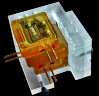
- Summary Table of Devices
See Table 4-12 for current state-of-the-art ambipolar devices applicable to small spacecraft.
4.6.3 In-Space Propellant-less Propulsion
Propellantless propulsion systems generate thrust via interaction with the surrounding environment (e.g., solar photon pressure, planetary magnetic fields, solar wind and ionospheric plasma pressures, and planetary atmospheres). By contrast, chemical and electric propulsion systems generate thrust by expulsion of reaction mass (i.e., propellant). Four propellant-less propulsion technologies have undergone in-space demonstrations to date, including solar sails, tethers, electric sails (and plasma brakes), and aerodynamic drag devices.
Solar Sails
- Technology Description
Solar sails use solar radiation pressure to generate thrust by reflecting photons via lightweight, highly reflective membranes. While no commercial products are presently available, a handful of missions have sought to demonstrate the technology using small spacecraft.
- Missions
NASA’s NanoSail-D2, Figure 4.49, launched as a 3U CubeSat secondary payload onboard the Fast, Affordable, Science and Technology Satellite (FASTSAT) bus in November 2010. The 10-m2 sail made of CP-1 deployed from a 650 km circular orbit and deorbited the spacecraft after 240 days in orbit (307).
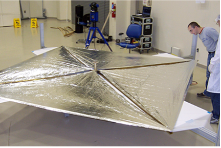
The Planetary Society’s LightSail 2 mission launched as a 3U CubeSat secondary payload on the Department of Defense’s Space Test Program (STP-2) in June 2019. The 32-m2 mylar solar sail was deployed at 720 km altitude and demonstrated apogee raising of ~10 km. Its mission was still ongoing as of September 2022 (308).
NASA’s Near-Earth Asteroid (NEA) Scout (Figure 4.50) mission launched as a secondary payload onboard Artemis I in November 2022. Unfortunately, contact was never made with the spacecraft, and the sail could not be tested. The 6U CubeSat was to deploy an 85-m2 solar sail and conduct a flyby of an asteroid within two years of launch (309) (310).
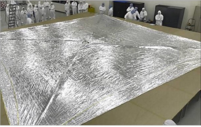
NASA’s Advanced Composite Solar Sail System (ACS3) technology demonstration uses composite materials for solar sail propulsion. The unfurled sail, approximately 9-m2, was deployed from a 12U CubeSat that launched in 2024 (311).
Tethers
- Technology Description
NASA has developed tether technology for space applications since the 1960s. A tether is nothing more than a long wire, conducting or nonconducting, deployed from a spacecraft in orbit. Two types of tethers and systems can be used for space transportation, with both having had their fundamental physical principles demonstrated in space:
Electrodynamic Tethers (EDT): A propulsive force of F=ILxB (Lorentz force) is generated on a spacecraft-tether system when a current I from an onboard power supply is fed into a tether of length L against the electromotive force (emf) induced in it by the geomagnetic field B. This concept will work near any planet with a magnetosphere (Earth, Jupiter, etc.). The resulting force may be used to accelerate the deorbit of a spacecraft, boost a spacecraft’s orbital altitude (by reversing the direction of current flow using an onboard power supply), or change its orbital inclination.
Momentum Exchange Tethers: Using completely different physical principles, long nonconducting tethers can exchange momentum between two masses in orbit to place one body into a higher orbit or a transfer orbit for lunar and planetary missions. Recently completed system studies of this concept indicate that it would be a relatively low-cost in-space asset with long-term, multi-mission capability.
- Missions
Important milestones include retrieval of a tether in space on the Tethered Satellite System (TSS) mission (TSS-1, 1992), the accidental momentum-exchange boost of the TSS-1R satellite when the tether broke during flight (TSS-1R, 1996), successful deployment of a 20 km-long tether in space (SEDS-1, 1993), closed-loop control of tether deployment (SEDS-2, 1994), and operation of an electrodynamic tether with tether current driven in both directions (i.e., power and thrust modes) (PMG, 1993).
More recently, Georgia Institute of Technology’s Prox-1 mission was launched as a secondary payload on the Department of Defense’s Space Test Program (STP-2) in June 2019. The 70 kg spacecraft served as the host and deployer for the LightSail 2 mission. The Prox-1 spacecraft housed a Tethers Unlimited Nanosat Terminator Tape (NSTT), shown in Figure 4.51, which deployed a 70-m tether in September 2019 to lower the orbit from 717 km. Data from the Space Surveillance Network indicate that the NSTT caused Prox-1 to deorbit more than 24 times faster than otherwise expected. This rate of orbital decay will enable Prox-1 to meet its 25-year deorbit requirement (312) (313) (314).
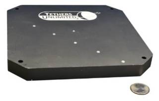
The Naval Postgraduate School’s NPSat-1 was launched as a secondary payload on STP-2 and deployed its NSTT in late 2020 (314). TriSept’s DragRacer technology demonstration mission, launched as a rideshare onboard an Electron rocket in November 2020, sought to conduct a direct comparison of the deorbiting rates of two Millennium Space Systems satellites, one of which used a 250-m NSTT (314) (315). A comparison of flight data for operation of the NSTT from each of these three missions has been publicly released (316).
Electric Sails
- Technology Description
An electric sail (also known as an electric solar wind sail or an E-sail) uses the dynamic pressure of the solar wind as a source of thrust. By using positively charged wires deployed from a spacecraft to create electric fields around each wire, a large “virtual” sail is created that deflects solar wind protons and extracts their momentum. Unlike EDTs, they do not derive thrust using the Lorentz force. Electric sails must be used outside the Earth’s magnetosphere.
A closely related concept to the electric sail is the plasma brake, an electrostatic deorbit propulsion system that, like the electric sail, uses Coulomb collisions between the charged wire and the ions in the surrounding environment (e.g., the Earth’s ionosphere) to generate an electrostatic force orthogonal to the tether direction, which lowers the spacecraft’s orbital altitude.
These technologies are relatively immature, but researchers in Europe and the U.S. have been making incremental progress on their development.
- Missions
The AuroraSat-1 satellite was launched on an Electron rocket on May 5, 2022 (158) (159). The spacecraft was built by SatRevolution with Aurora Propulsion Technologies providing the payloads. The mission serves as a technology demonstration for a Plasma Brake module (157) (Figure 4.52) and an Aurora Resistojet Module for Attitude control (ARM-A) (156) (Figure 4.19), both produced by Aurora. The Plasma Brake module on AuroraSat-1 is a dual-redundant system for demonstration purposes. A 50-m tether will be deployed to demonstrate its deorbiting capability.
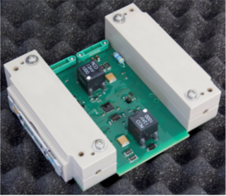
Aerodynamic Drag
- Technology Description
Satellites have historically deorbited from low-Earth orbits with the aid of thrusters or passive atmospheric drag. Given the increasing rate of new spacecraft launched and the associated potential for new orbital debris following completion of missions, orbital debris management has gained increasing attention. Space debris poses a growing threat to active satellites and human activity in space. Allowing decades for defunct spacecraft to decay naturally from low-Earth orbit is no longer sufficient, as the Federal Communications Commission in late 2022 adopted a draft rule that requires <2,000 km altitude spacecraft to deorbit within 5 years of mission completion (318). Aerodynamic drag devices may provide one method to rapidly remove spacecraft from low-Earth orbits upon mission completion.
Below about 1,000 km altitude, the atmosphere exerts a measurable drag force opposite the relative motion of any spacecraft, which results in a slow orbital decay. The intensity of the drag force exerted on the spacecraft depends on numerous factors such as local atmospheric density, the spacecraft forward facing area, the spacecraft velocity, and a drag coefficient. The drag coefficient accounts for the drag force’s dependence on an object’s unique geometric profile. While the spacecraft velocity and local atmospheric density are largely mission dependent, a spacecraft’s forward-facing area and drag coefficient can be altered by introducing aerodynamic drag devices such as exo-brakes and ballutes. These deployable or inflatable parachutes and balloons can greatly increase the drag force exerted on spacecraft by an order of magnitude or more and significantly increase the rate of orbital decay.
Furthermore, aerodynamic drag devices may be useful to reduce the spacecraft propellant mass required for orbit capture and disposal at other planetary bodies, given sufficient atmospheric density exists.
For further details on these devices, see the Deorbit Systems chapter.
| Table 4-1: Hydrazine Chemical Propulsion | ||||||||||||
|---|---|---|---|---|---|---|---|---|---|---|---|---|
| Manufacturer | Product | Propellant | Thrust per Thruster (Quantity) | Specific Impulse | Total Impulse | Mass | Envelope | Power | ACS | PMI Status | Missions | References |
| — | — | — | [N] | [s] | [kN-s] | [kg] | [cm3 or U] | [W] | Y/N | C,D,E,F | — | — |
| Integrated Propulsion Systems | ||||||||||||
| Aerojet Rocketdyne USA | MPS-120 | Hydrazine | 0.25 – 1.0 (4) | – | 2 (2U) 0.8 (1U) | 2.5† (2U) 1.6† (1U) | 2U 1U | – | Y | D | – | (99) |
| Aerojet Rocketdyne USA | MPS-125 | Hydrazine | 0.25 – 1.0 (4) | – | 14 (8U) 9.9 (6U) 5.2 (4U) | 12.1† (8U) 9.3† (6U) 6.2† (4U) | 8U 6U 4U | – | Y | D | – | (99) |
| Stellar Exploration USA | Monopropellant CubeSat System | Hydrazine | – | 200s | – | – | – | – | Y | F | Echostar Global 3, NASA Capstone | (17) (18) (19) (20) (100) |
| Stellar Exploration USA | Bipropellant CubeSat system | Hydrazine/ NTO | – | 285 | – | – | – | – | Y | D | – | (100) |
| Thruster | ||||||||||||
| Aerojet Rocketdyne USA | MR-103 | Hydrazine | 1 | 202 – 224 | 183 | 0.33 – 0.37 | – | < 16 | – | F | numerous | (8) |
| Aerojet Rocketdyne USA | MR-106 | Hydrazine | 22 | 228 – 235 | 561 | 0.59 | – | < 36 | – | F | numerous | (8) |
| Aerojet Rocketdyne USA | MR-111 | Hydrazine | 4 | 219 – 229 | 262 | 0.37 | – | < 16 | – | F | numerous | (8) |
| Aerojet Rocketdyne USA | MR-401 | Hydrazine | 0.08 | 182 | 200 | 0.60 | – | – | – | F | Numerous | (8) |
| ArianeGroup France | 1 N | Hydrazine | 1 | 200 – 223 | 135 | 0.29 | – | – | – | F | ALSAT-2, numerous | (6) (7) |
| ArianeGroup France | 20 N | Hydrazine | 20 | 222 – 230 | 517 | 0.65 | – | – | – | F | Numerous | (7) |
| IHI Aerospace Japan | MT-9 | Hydrazine | 1 | 208 – 215 | (100 kg)* | – | – | – | – | F | Numerous | (16) |
| IHI Aerospace Japan | MT-8A | Hydrazine | 5 | 212 – 225 | (190 kg)* | – | – | – | – | F | Numerous | (16) |
| IHI Aerospace Japan | MT-2 | Hydrazine | 20 | 210 – 226 | (115 kg)* | – | – | – | – | F | Numerous | (16) |
| Moog USA | MONARC-1 | Hydrazine | 1 | 227 | 111 | 0.38 | 113×50 mm | 18 (valve) | – | F | numerous | (12) |
| Moog USA | MONARC-5 | Hydrazine | 4.5 | 226 | 613 | 0.49 | 203×380 mm | 18 (valve) | – | F | NASA SMAP, numerous | (12) (13) |
| Moog USA | MONARC-22-6 | Hydrazine | 22 | 228 | 533 | 0.72 | 203×380 mm | 30 (valve) | – | F | numerous | (12) |
| Moog USA | MONARC-22-12 | Hydrazine | 22 | 228 | 1,173 | 0.69 | 229×530 mm | 30 (valve) | – | F | numerous | (12) |
| Northrop Grumman USA | MRE-0.1 | Hydrazine | 1 | 216 | (34 kg)* | 0.5 | 114×175 mm | 15 | – | F | numerous | (14) |
| Northrop Grumman USA | MRE-1.0 | Hydrazine | 5 | 218 | (544 kg)* | 0.5 | 114×188 mm | 15 | – | F | numerous | (14) |
| Northrop Grumman USA | MRE-4.0 | Hydrazine | 18 | 217 | (249 kg)* | 0.5 | 61×206 mm | 30 | – | F | numerous | (14) |
| Rafael Israel | 1N | Hydrazine | 1 | 205 – 214 | 100 | 0.31 | – | 9 (valve) | F | numerous | (15) | |
| Rafael Israel | 5N | Hydrazine | 6 | 210 – 220 | 74 | 0.31 | – | 9 (valve) | F | numerous | (15) | |
| Rafael Israel | 25N | Hydrazine | 28 | 205 – 220 | 100 | 0.53 | – | 15 (valve) | F | numerous | (15) | |
| Note that all data is documented as provided in the references. Unless otherwise published, do not assume the data has been independently verified. † denotes a wet mass, ‡ denotes a dry mass, “-“ = denotes data not available or applicable, * denotes mass of propellant throughput, rather than total impulse | ||||||||||||
| Table 4-3: Alternative Monopropellant and Bipropellant Propulsion | ||||||||||||
|---|---|---|---|---|---|---|---|---|---|---|---|---|
| Manufacturer | Product | Propellant | Thrust per Thruster (Quantity) | Specific Impulse | Total Impulse | Mass | Envelope | Power | ACS | PMI Status | Missions | References |
| — | — | — | [N] | [s] | [kN-s] | [kg] | [cm3 or U] | [W] | Y/N | C,D,E,F | — | — |
| Integrated Propulsion Systems | ||||||||||||
| Aerojet Rocketdyne USA | MPS-130 | ASCENT | 0.25 – 1.0 (4) | – | 2.7 (2U) 1.1 (1U) | 2.8† (2U) 1.7† (1U) | 2U 1U | – | Y | D | – | (98) (99) |
| Aerojet Rocketdyne USA | MPS-135 | ASCENT | 0.25 – 1.0 (4) | – | 19.4 (8U) 13.7 (6U) 7.3 (4U) | 14.7† (8U) 11.2† (6U) 7.2† (4U) | 8U 6U 4U | – | Y | D | – | (99) |
| Aerospace Corp. USA | HyPer | H₂O₂ | – | – | – | – | 0.25U | – | – | D | – | (101) |
| Benchmark Space Systems USA | Halcyon | HTP | 0.25 1 5 10 | 150 – 170 | (1.56 kg)* (6.6 kg)* (32.5 kg)* (65 kg)* | – | – | < 4 | Y | E | Transporter 2 (Undisclosed missions) | (36) (102) (103) (104) |
| Benchmark Space Systems USA | Halcyon Avant | HTP + Fuel | 2 10 22 | 290 – 310 | (6.8 kg)* (34 kg)* (74.8 kg)* | – | – | < 15 | Y | F | Sherpa-TLC2 | (34) (35) (104) |
| Benchmark Space Systems USA | Peregrine | HTP & Alcohol | 0.1 – 22 (1-8) | 270 – 300 | 5 – 150 | – | – | – | – | D | – | (104) |
| ECAPS Sweden | SkySat 1N HPGP Propulsion System | LMP-103S | 1.0 (4) | > 200 | 21 | 22† | 55 x 55 x 15 | 10 | Y | F | Skysat, PRISMA, Astroscale ELSA-d | (24) (25) (26) (27) (105) (106) (107) (108) |
| Busek USA | BGT-X5 System | ASCENT | 0.5 | 220 – 225 | 0.57 | 1.5† | 1U | 20 | N | D | – | (112) (113) (114) |
| Cornell University USA | Cislunar Explorer | Water (Electrolysis) | – | – | – | – | 6U total (2-units) | – | – | E | CubeQuest Challenge (removed from Artemis 1) | (37) (38) (39) |
| CU Aerospace USA | MPUC | (CMP-X) Peroxide/ Ethanol blend | 0.23 | 178 | 1.4 (1.5U) 2.1 (2U) | 2.5† (1.5U) 3.3† (2U) | 1.5U 2U | 3 | N | D | – | (46) (47) |
| Dawn Aerospace New Zealand | CubeDrive | Nitrous Oxide & Propylene | 0.5 | – | 0.425 1.450 | 1.17† 2.70† | 0.8U 2U | – | N | F | Multiple | (45) (115) |
| Dawn Aerospace New Zealand | SatDrive | Nitrous Oxide & Propylene | 0.5 – 16.7 | 250 – 280 | 5 – 500 | – | – | – | N | F | Multiple | (45) (115) |
| Moog USA | Monopropellant Propulsion Module | Green or ‘Traditional’ | 0.5 | 224 | 0.5 | 1.0† | 1U | 2 x 22.5 W/Thruster | N | D | – | (116) |
| Rubicon Space Systems USA | Sprite | ASCENT | 0.05 – 0.15 | >195 | > 1 | < 2.2† | 1.5U | 2 – 16 | N | E | GPDM | (110) (111) (117) |
| NASA MSFC USA | LFPS | ASCENT | 0.1 (4) | > 200s | > 3.5 | < 5.5† | ~2.4U | 15 – 47 | Y | E | Lunar Flashlight | (32) (33) |
| NanoAvionics Lithuania | EPSS C1K | IADN-blend | 1.0 BOL 0.22 EOL | 213 | > 0.4 | 1.2† | 1.3U | 9.6 (preheat) 1.7 (firing) | N | F | Lituanica-2 | (43) (44) |
| NanoAvionics Lithuania | EPSS C2 | IADN-blend | 1.0 BOL 0.25 EOL | 220 | > 1.7 | 2.6† | 2U | – | N | D | – | (43) |
| Note that all data is documented as provided in the references. Unless otherwise published, do not assume the data has been independently verified. † denotes a wet mass, ‡ denotes a dry mass, “-“ = denotes data not available or applicable, * denotes mass of propellant throughput, rather than total impulse, BOL = Beginning of Life, EOL = End of Life | ||||||||||||
| Table 4-3 (cont.): Other Monopropellant and Bipropellant Propulsion | ||||||||||||
|---|---|---|---|---|---|---|---|---|---|---|---|---|
| Manufacturer | Product | Propellant | Thrust per Thruster (Quantity) | Specific Impulse | Total Impulse | Mass | Envelope | Power | ACS | PMI Status | Missions | References |
| — | — | — | [N] | [s] | [kN-s] | [kg] | [cm3 or U] | [W] | Y/N | C,D,E,F | — | — |
| Integrated Propulsion Systems (cont.) | ||||||||||||
| Tethers Unlimited USA (Subsidiary of ARKA Group LP) | HYDROS-C | Water (Electrolysis) | > 1.2 | > 310 | > 2.1 | 2.7† | 19 x 13 x 9.2 | 5 – 25 | N | F | Pathfinder Technology Demonstration | (41) (42) (118) (119) |
| Tethers Unlimited USA (Subsidiary of ARKA Group LP) | HYDROS-M | Water (Electrolysis) | > 1.2 (1) | > 310 | > 18 | 13.7† | 38.1 dia. x 19.1 | 7 – 40 | N | D | – | (120) |
| VACCO USA | ArgoMoon Hybrid MiPS | LMP-103S/ R134a | 0.1 (1) | 190 | 0.78 | 2.07† | 1.3U | 4.3 20 (max) | Y | F | ArgoMoon (Artemis I) | (27) (28) (29) |
| VACCO USA | Green Propulsion System (MiPS) | LMP-103S | 0.1 (4) | 190 | 3.3 | 5† | 3U | 15 (max) | Y | D | – | (121) |
| VACCO USA | Integrated Propulsion System | LMP-103S | 1 (4) | 200 | 12 | 14.7† | 11U | 50 (max) | Y | D | – | (48) (49) |
| Thruster Heads | ||||||||||||
| Aerojet Rocketdyne USA | GR-1 | ASCENT | 0.3 – 1.4 | 231 | (12 kg)* | – | – | 18 (max) | – | F | GPIM | (8) (30) (31) |
| Aerojet Rocketdyne USA | GR-22 | ASCENT | 8 – 25 | 250 | 74 | – | – | 28 | – | F | GPIM | (8) (30) (31) |
| Benchmark Space Systems USA | Felicette | HTP | 0.4 – 1.2 | 161 | > 10 | – | – | – | – | E | Transporter 2 (Undisclosed missions) | (36) (104) |
| Benchmark Space Systems USA | Lynx | HTP | 2 – 2.5 | 295 | > 20 | – | – | – | – | D | – | (104) |
| Benchmark Space Systems USA | Ocelot | HTP | 18 – 22 | 302 | > 240 | – | – | – | – | F | Sherpa-TLC2 | (34) (35) (104) |
| ECAPS Sweden | 0.1 N HPGP | LMP-103S | 0.03 – 0.1 | 196 – 209 | (1 kg)* | 0.04 excl. FCV | – | 6.3 – 8 | – | F | ArgoMoon | (24) (27) (107) |
| ECAPS Sweden | 1 N HPGP | LMP-103S | 0.25 – 1 | 204 – 235 | (24 kg)* | 0.38 | – | 8 – 10 | – | F | PRISMA, SkySat, ELSA-d | (24) (25) (26) (27) (107) (108) |
| ECAPS Sweden | 1 N GP | LMP-103S/LT | 0.25 – 1 | 194 – 227 | (5 – 8 kg)* | 0.38 | – | 8 – 10 | – | D | (108) | |
| ECAPS Sweden | 5 N HPGP | LMP-103S | 1.5 – 5.5 | 239 – 253 | – | 0.48 | – | 15 – 25 | – | D | – | (107) |
| ECAPS Sweden | 22 N HPGP | LMP-103S | 5.5 – 22 | 243 – 255 | (150 kg)* | 1.1 | – | 25 – 50 | – | D | – | (107) |
| Dawn Aerospace New Zealand | B20 Thruster | Nitrous Oxide & Propylene | 6.1 – 16.7 | – | – | 0.6 | 17.6 x 8.0 x 7.9 | – | – | F | numerous | (45) |
| Dawn Aerospace New Zealand | B1 Thruster | Nitrous Oxide & Propylene | 0.46 – 1.28 | – | – | 0.26 | 10.8 x 7.9 x 4.0 | – | – | F | numerous | (45) |
| Rubicon Space Systems USA | 0.1N | ASCENT | 0.1 | >195 | 5.7 | 0.06 | 2.5 dia x 4 | 8 | – | E | Lunar Flashlight, GPDM | (32) (33) (109) (110) (111) |
| Rubicon Space Systems USA | 1N LT (HT) | ASCENT | 1 | >250 | 12 (33) | 0.25 | 6 dia x 16 | 15 (25) | – | D | – | (109) |
| Rubicon Space Systems USA | 5N LT (HT) | ASCENT | 5 | >250 | 12 (118) | 0.30 | 6 dia x 16 | 25 | – | D | – | (109) |
| Note that all data is documented as provided in the references. Unless otherwise published, do not assume the data has been independently verified. † denotes a wet mass, ‡ denotes a dry mass, “-“ = denotes data not available or applicable, * denotes mass of propellant throughput, rather than total impulse | ||||||||||||
| Table 4-4: Hybrid Chemical Propulsion | ||||||||||||
|---|---|---|---|---|---|---|---|---|---|---|---|---|
| Manufacturer | Product | Propellant | Thrust (Quantity) | Specific Impulse | Total Impulse | Mass | Envelope | Power | ACS | PMI Status | Missions | References |
| — | — | — | [N] | [s] | [kN-s] | [kg] | [cm3 or U] | [W] | Y/N | C,D,E,F | — | — |
| Aerospace Corp. USA | Propulsion Unit for CubeSats | Paraffin/Nitrous Oxide | – | – | – | – | 1U | – | – | D | (60) | |
| JPL USA | Hybrid Rocket | PMMA/GOX | – | > 300 | – | – | – | – | – | D | – | (54) (55) (56) (57) |
| NASA Ames USA | Hybrid Rocket | PMMA/ Nitrous Oxide | 25 | 247 | – | – | – | – | – | D | (58) (59) | |
| Parabilis Space Technologies USA | ROMBUS | Various/N2O | 222 | 260 | 44.6 | 49 | 55 dia. x 46 | – | Y | D | (61) | |
| Parabilis Space Technologies USA | NanoSat Obrital Transfer System | HTPB/N2O | 9.4 | 245 | – | – | – | – | Y | C | (62) | |
| Utah State Univ. USA | Green Hybrid Rocket | ABS/Nytrox | 25 – 50 | 220 – 300 | – | – | – | < 30 for 1-2 seconds | – | D | (52) (53) | |
| Utah State Univ. USA | Green Hybrid Rocket | ABS/GOX | 8 | 215 | – | – | – | – | – | D | – | (50) (51) |
| Note that all data is documented as provided in the references. Unless otherwise published, do not assume the data has been independently verified. † denotes a wet mass, ‡ denotes a dry mass, “-“ = denotes data not available or applicable | ||||||||||||
| Table 4-5: Cold Gas Propulsion | ||||||||||||
|---|---|---|---|---|---|---|---|---|---|---|---|---|
| Manufacturer | Product | Propellant | Thrust (Quantity) | Specific Impulse | Total Impulse | Mass | Envelope | Power | ACS | PMI Status | Missions | References |
| — | — | — | [mN] | [s] | [N-s] | [kg] | [cm3 or U] | [W] | Y/N | C,D,E,F | — | — |
| Integrated Propulsion Systems | ||||||||||||
| Aerospace Corp. USA | MEPSI | R236fa | 20 | – | – | 0.188† | – | – | Y | E | STS-113 and STS-116 | (63) |
| Benchmark Space Systems USA | Starling | Nitrogen | 10 – 1000 | 70 | – | 0.75† | 0.5U | < 4 | Y | D | – | (104) |
| GomSpace Sweden | NanoProp CGP3 | Butane | 0.01 – 1 (4) | 60 – 110 | 40 | 0.35† | 5 x 10 x 10 | < 2 | Y | E | TW-1 | (71) (73) (74) (124) |
| GomSpace Sweden | NanoProp 6U | Butane | 0.1 – 10 (4) | 60 – 110 | 80 | 0.900† | 2 x 10 x 20 | < 2 | Y | F | GOMX-4B | (71) (72) (125) |
| Lightsey Space Research USA | BioSentinel Propulsion System | R236fa | 20 | 47 | 79.8 | 1.28† | 4 x 10 x 20 | < 1 idle, < 4 operating | Y | E | BioSentinel | (75) (76) (77) (78) |
| Microspace Rapid Pte Ltd Singapore | POPSAT-HIP1 | Argon | 0.083 – 1.1 (8) | 43 | – | – | – | – | – | E | POPSAT-HIP1 | (70) |
| T4i Italy | IANUS | R134a | 6.8/10.6/26.2 (x/y/z) | 40 | 38 | 0.5‡ | 0.5 | <40 | Y | E | Hera Milani | (126) |
| T4i Italy | PERSEUS | R134a | 27/9/9 (x/y/z) | 40 | 450 | 2.5‡ | 2.5 | <20 | Y | F | Iperdrone.0 | (126) |
| ThrustMe France | I2T5 | Iodine | 0.35 | – | 75 | 0.9† | 0.5U | 5 | N | F | Xiaoxiang 1-08, NAPA-2, Spire L3C Demo, Robusta-3A (2024**) | (79) (80) (81) (82) |
| UTIAS/SFL Canada | CNAPS | Sulfur Hexafluoride | 12.5 – 50 | 40 | 100 | – | – | – | N | F | CanX-4/CanX-5 | (66) (67) (68) (69) |
| VACCO USA | NEA Scout | R236fa | 25 (6) | – | 500 | 2.54† | 2U | < 55 warmup < 9 operating | Y | E | NEA Scout | (90) (91) (92) |
| VACCO USA | MiPS Standard | R236fa | 25 (4) | – | 82 – 515 | 0.85 – 2.46† | 0.4 – 1.5U | < 12 | Y | D | – | (127) |
| VACCO USA | MarCO-A and -B MiPS | R236fa | 25 (8) | – | 755 | 3.49† | 8 x 15 x 20 | – | Y | E | MarCO-A & -B | (86) (87) (88) (89) |
| VACCO USA | C-POD | R236fa | 10 (8) | 40 | 186 | 1.25† | 1U | 5 | Y | E | CPOD | (83) (84) (85) |
| Thruster Heads | ||||||||||||
| Marotta USA | CGMT | Nitrogen | 105 – 2360 | – | – | < 0.06 | – | < 7 | – | F | NMP ST5 | (64) (65) |
| Moog USA | 058E143-146 | Nitrogen | 10 – 40 | 60 | – | 0.04 | 1.4 x 5.7 | < 10 | – | F | CHAMP, GRACE | (128) |
| Moog USA | 058E142A | Nitrogen | 120 | 57 | – | 0.016 | 1.4 x 2.0 | < 35 | – | F | Spitzer Space Telescope | (128) |
| Moog USA | 058E151 | Nitrogen | 120 | 65 | – | 0.07 | 1.9 x 4.1 | < 10.5 | – | F | Spitzer Space Telescope | (128) |
| Moog USA | 058-118 | Nitrogen | 3600 | 57 | – | 0.023 | 0.7 x 2.5 | < 30 | – | F | SAFER, Pluto Fast Flyby | (128) |
| Moog USA | 58E163A | Nitrogen, Xenon, Argon | 1300 | 70 N2, 21 Xe, 54 Ar | – | 0.115 | 2.4 x 5.3 | < 10.5 | – | F | GEO applications | (128) |
| Note that all data is documented as provided in the references. Unless otherwise published, do not assume the data has been independently verified. † denotes a wet mass, ‡ denotes a dry mass, “-“ = denotes data not available or applicable, ** anticipated launch date | ||||||||||||
| Table 4-6: Solid Motor Chemical Propulsion | ||||||||||||
|---|---|---|---|---|---|---|---|---|---|---|---|---|
| Manufacturer | Product | Propellant | Thrust (Quantity) | Specific Impulse | Total Impulse | Mass | Envelope | Power | ACS | PMI Status | Missions | References |
| — | — | — | [N] | [s] | [N-s] | [kg] | [cm3 or U] | [W] | Y/N | C,D,E,F | — | — |
| Integrated Propulsion Systems | ||||||||||||
| PacSci EMC USA | MAPS | – | – | – | – | – | – | – | – | E | PacSciSat | (94) (95) |
| Thruster Heads | ||||||||||||
| Industrial Solid Propulsion USA | ISP 30 sec. Motor | 80% Solids HTPB/AP | 37 | 187 | 996 | 0.95† | 5.7 | – | – | D | Optical target at Kirtland AFB | (130) |
| Northrop Grumman USA | STAR 3 | TP-H-3498 | 461 | 266 | 1,250 | 1.16† | 8 dia. x 29 | – | – | E | Mars Exploration Rover Spirit lander | (131) |
| Northrop Grumman USA | STAR 4G | TP-H-3399 | 258 | 269 | 2,650 | 1.5† | 11.3 dia. x 13.8 | – | – | D | – | (131) |
| Note that all data is documented as provided in the references. Unless otherwise published, do not assume the data has been independently verified. † denotes a wet mass, ‡ denotes a dry mass, “-“ = denotes data not available or applicable | ||||||||||||
| Table 4-7: Electrothermal Electric Propulsion | ||||||||||||
|---|---|---|---|---|---|---|---|---|---|---|---|---|
| Manufacturer | Product | Propellant | Thrust* | Specific Impulse* | Total Impulse* | Mass | Envelope | Power | ACS | PMI Status | Missions | References |
| — | — | — | [mN] | [s] | [N-s] | [kg] | [cm3 or U] | [W] | Y/N | C,D,E,F | — | — |
| Integrated Propulsion Systems | ||||||||||||
| AIS USA | AIS-SWAG1-PQ | Adamantane | 0.12 | 20 | 3 | 0.224† | 4.2 x 4.2 x 5.4 | 5 | N | D | – | (317) |
| AIS USA | AIS-SWAG1-DUO | Adamantane | 0.24 | 20 | 6 | 0.449† | 8.6 x 4.2 x 5.4 | 10 | N | D | – | (317) |
| AIS USA | AIS-SWAG1-QUAD | Adamantane | 0.48 | 20 | 12 | 0.898† | 8.6 x 8.6 x 5.4 | 20 | N | D | – | (317) |
| Aurora Finland | ARM-A | Water | 0.5 | 100 | 70 | 0.280† | 0.3U | 10£ | Y | E | AuroraSat-1 (2022), ORB-12 STRIDER | (156) (158) (159) (280) |
| Aurora Finland | ARM-C | Water | 1 | – | – | 0.050† | 45 | 12 (max) | N | D | – | (162) |
| Benchmark Space Systems USA | Starling Ardent | Nitrogen | 10 – 1000 | 70 – 140 | – | 1.15 | 1U | 10 – 100 | Y | D | – | (104) |
| Bradford Space Netherlands | Comet-1000 | H2O | 17 | 175 | 1,150 | 1.55† | 2,300 | 50 (max) | N | F | HawkEye 360, Capella Space, Transporter 7 | (134) (135) (136) (137) |
| Bradford Space Netherlands | Comet-8000 | H2O | 17 | 175 | 8,348 | 6.68† | 23,760 | 55 (max) | N | F | BlackSky | (134) (137) (138) |
| CU Aerospace USA | CHIPS-180 | R134a | 15 | 67 | 176 | 1.03† | 540 | 20 | Y | D | – | (319) (320) (321) (322) |
| CU Aerospace USA | CHIPS-500 | R134a | 25 | 69 | 505 | 1.84† | 1300 | 25 | Y | D | – | (319) (320) (321) (322) |
| CU Aerospace USA | CHIPS-1000 | R134a | 31 | 70 | 1,030 | 3.13† | 2500 | 30 | Y | D | – | (319) (320) (321) (322) |
| CU Aerospace and VACCO USA | PUC | SO2 | 4.5 | 70 | 184 | 0.72† | 0.35U | 15 | N | E | 8 flight units delivered to AFRL | (139) (140) (141) |
| CU Aerospace USA | MVP | Delrin Fiber | 4.5 | 66 | 280 | 1.06† | 0.93U | 45 | N | E | DUPLEX (2025) | (142) (143) (144) (145) (154) (155) |
| EPL USA | APS 100 | Ammonia | 28 | 280 | 2,200 | 2.63† | 2.5U | 100 | N | D | – | (323) |
| EPL USA | APS 500 | Ammonia | 150 | 350 | 25,200 | 13.4† | 27,300 | 450 | N | E | Atomos Space (2024**) | (323) (324) |
| Pale Blue Japan | PBR-10 | Water | 1.0 | – | 55 | 0.6† | 0.5U | 6 | N | E | ArkEdge AE1c | (325) (326) |
| Pale Blue Japan | PBR-20 | Water | 1.0 | – | 220 | 1.5† | 1U | 20 | N | E | ArkEdge OPTIMAL-1; SPHERE-1 EYE | (160) (161) (325) |
| Pale Blue Japan | PBR-30 | Water | 12 | – | 400 | 2.1† | 2U | 35 | N | D | – | (325) |
| SteamJet Space Systems UK | Steam TunaCan Thruster | Water | 6 | 172 | 219 | 0.54† | 402 | < 19.9 | N | D | – | (146) |
| SteamJet Space Systems UK | Steam Thruster One | Water | 6 | 172 | – | – | – | 19.9 | N | D | – | (147) |
| Thruster Heads | ||||||||||||
| SITAEL Italy | XR-50 | Ar, Xe, N2 | 100 | 55-85 | ≤ 72,000 | 0.22‡ | 45.8 | ≤ 50 | – | D | – | (327) (328) |
| SITAEL Italy | XR-100 | Ar, Xe, N2 | 125 | 63-105 | ≤ 90,000 | 0.22‡ | 45.8 | ≤ 80 | – | D | – | (327) (328) |
| SITAEL Italy | XR-150 | Ar, Xe, N2 | 250 (Ar) 100 (Xe) | 58-110 | ≤ 180,000 | 0.22‡ | 45.8 | ≤ 95 | – | D | – | (327) (328) |
| Note that all data is documented as provided in the references. Unless otherwise published, do not assume the data has been independently verified. *nominal values (see references for full performance ranges), ** anticipated launch date, † denotes a wet mass, ‡ denotes a dry mass, £ per active thruster, “-“ = denotes data not available or applicable | ||||||||||||
| Table 4-8: Electrospray Electric Propulsion | ||||||||||||
|---|---|---|---|---|---|---|---|---|---|---|---|---|
| Manufacturer | Product | Propellant | Thrust* | Specific Impulse* | Total Impulse* | Mass | Envelope | Power | Neutralizer | PMI Status | Missions | References |
| — | — | — | [mN] | [s] | [N-s] | [kg] | [cm3 or U] | [W] | — | C,D,E,F | — | — |
| Integrated Propulsion Systems | ||||||||||||
| Busek USA | CMNT (4x heads) | EMI-Im (ionic) | 4 x 20 | 225 | 980 | 14.8† | 29U | 16.5 | Carbon Nanotube | F | LISA Pathfinder | (163) |
| Busek USA | BET-MAX (Config. A) | EMI-Im (ionic) | 4 x 55 | 850 | 4 x 92§ | 0.8† | 1250 | 12 | Carbon Nanotube | E | US Government | (329) (330) (331) (332) (333) (334) (335) |
| Busek USA | BET-MAX (Config. B) | EMI-Im (ionic) | 4 x 40 | 2300 | 4 x 250 | 0.8† | 1250 | 14 | Carbon Nanotube | D | – | (335) |
| Enpulsion Austria | Nano | Indium (FEEP) | 330 | 1,500 (alpha); 3,000 (gamma) | > 3,000 (alpha); > 5,000 (gamma) | 0.90† | 10 x 10 x 8.3 | 40 | Thermionic | F | Flock 3p’, ICEYE X2, Harbinger, NetSat, and others | (164) (165) (166) (167) (168) (169) (170) (171) (336) (337) (338) |
| Enpulsion Austria | Nano R3 | Indium (FEEP) | 350 | 1,500 (alpha); 2,700 (gamma) | > 3,000 (alpha); > 5,000 (gamma) | 1.4† | 9.8 x 9.9 x 9.5 | 45 | Thermionic | E | (Evolution of Nano design) | (171) (172) (339) |
| Enpulsion Austria | Micro R3 | Indium (FEEP) | 1,000 | 2,100 (alpha); 2,750 (gamma) | > 25,000 (alpha); > 35,000 (gamma) | 3.9† | 14 x 12 x 13.3 | 105 | Thermionic | F | GMS-T | (172) (173) (340) (341) |
| Enpulsion Austria | Neo | Indium (FEEP) | 20,000 | 1,500 | > 550,000 | 30† | 34 x 34 x 15 | 800 | Thermionic | D | – | (342) |
| Morpheus Space Germany | NanoFEEP (2x heads) | Gallium (FEEP) | < 40 | – | – | 0.16‡ | 9 x 2.5 x 4.3 | < 3 | Propellant-less | E | UWE-4 | (174) (175) (343) (344) |
| Morpheus Space Germany | MultiFEEP (2x heads) | Gallium (FEEP) | < 140 | – | – | 0.28‡ | 9 x 4.5 x 4.5 | < 19 | Propellant-less | D | – | (343) |
| Note that all data is documented as provided in the references. Unless otherwise published, do not assume the data has been independently verified. *nominal values (see references for full performance ranges), ** anticipated launch date, † denotes a wet mass, ‡ denotes a dry mass, § demonstrated, “-“ = denotes data not available or applicable | ||||||||||||
| Table 4-9: Gridded-Ion Electric Propulsion | |||||||||||||
|---|---|---|---|---|---|---|---|---|---|---|---|---|---|
| Manufacturer | Product | Type | Propellant | Thrust* | Specific Impulse* | Total Impulse* | Mass | Envelope | Power | Cathode Type | PMI Status | Missions | References |
| — | — | — | [mN] | [s] | [kN-s] | [kg] | [cm3 or U] | [W] | — | C,D,E,F | — | — | |
| Integrated Propulsion Systems | |||||||||||||
| Avant Space Russia | GT-50 | RF Ion | Xenon | < 7 | – | – | < 8† | < 4U | < 240 | Hollow | D | – | (345) (346) |
| Busek USA | BIT-3 | RF Ion | Iodine | 1.0 | 1,960 | 31.7 | 2.9† | 18 x 8.8 x 10.2 | 70 | RF | E | Lunar IceCube; LunaH-Map | (188) (189) (190) (191) (192) (193) (347) (348) (349) (350) (351) (352) |
| Pale Blue Japan | PBI | RF Ion | Water | 0.35 | 2000 | 7 | 1.6† | 10 x 10 x 11 | 60 | RF | E | ON-SCV 018; ON-SCV 021 | (353) (354) (355) (356) (357) |
| ThrustMe France | NPT30-I2 | RF Ion | Iodine | < 1.3 | 2,400 | 5.5 (1U) 14 (1.5U) | 1.2† (1U) 1.85† (1.5U) | 1U 1.5U | < 81 | Thermionic | F | Beihangkongshi-1; NORSAT-TD | (182) (183) (184) (185) (186) (187) (358) (359) (360) |
| Thruster Heads | |||||||||||||
| Ariane Group Germany | RIT µX | RF Ion | Xenon | < 0.5 | – | – | 0.44‡ | 7.8 x 7.8 x 7.6 | < 50 | RF | D | – | (361) (362) (363) (364) (365) (366) |
| Ariane Group Germany | RIT 10 EVO | RF Ion | Xenon | < 15 | – | – | 1.8‡ | 18.6 x 18.6 x 13.4 | < 435 | Hollow | E | (Identical to flight-heritage RIT-10 with contemporary grid design) | (361) (363) (367) |
| QinetiQ UK | T5 | DC Ion | Xenon | < 20 | < 3,000 | – | 2‡ | 19 x 19 x 24.2 | < 600 | Hollow | F | GOCE | (178) (179) (180) (181) |
| Note that all data is documented as provided in the references. Unless otherwise published, do not assume the data has been independently verified. *nominal values (see references for full performance ranges), ** anticipated launch date, † denotes a wet mass, ‡ denotes a dry mass, “-“ = denotes data not available or applicable, RF = Radio Frequency, DC = Direct Current, DDL = Destroyed During Launch | |||||||||||||
| Table 4-10: Hall-Effect Electric Propulsion Thrusters | ||||||||||||
|---|---|---|---|---|---|---|---|---|---|---|---|---|
| Manufacturer | Product | Propellant | Thrust* | Specific Impulse* | Total Impulse* | Mass | Envelope | Thruster Power* | Cathode Type | PMI Status | Missions | References |
| — | — | — | [mN] | [s] | [kN-s] | [kg] | [cm3 or U] | [W] | Notes | C,D,E,F | — | — |
| Aliena Pte Ltd Singapore | MUSIC-SI | Xenon | < 0.25 | < 200 | 1 | 2† | 1.5U | 20 | None | E | NuX-1 | (275) (276) (277) (278) (279) |
| Aliena Pte Ltd Singapore | MUSIC-HM | Xenon | 3 | 1,000 | 15 | 5† | 4U | 100 | EM-HL | E | ORB-12 STRIDER | (275) (279) (280) |
| Astra USA | ASE | Xenon | 25 | 1,400 | 300 | 1.0 | – | 400‡ | CM-HL | F | Sherpa-LTE | (218) (220) (219) (220) (221) (223) (224) |
| Astra USA | ASE | Krypton | 18 | 1,300 | 300 | 1.0 | – | 400‡ | CM-HL | D | – | (218) |
| Busek USA | BHT-100 | Xenon | 6.3 | 1,086 | 150 | 1.2 | 275 wo cath. | 105 | EM-SH | D | – | (203) (368) |
| Busek USA | BHT-200 | Xenon | 13 | 1,390 | 84§ | 1.2 | 675 wo cath. | 250‡ | EM-SH | F | TacSat-2, FalconSat-5, -6 | (203) (204) (205) (206) |
| Busek USA | BHT-200-I | Iodine | 14 | 1390 | – | 1.2 | 675 wo cath. | 250 | EM-SH | E | NASA iSat (Cancelled) | (204) (206) (207) |
| Busek USA | BHT-350 | Xenon | 17 | 1,244 | 212§ | 1.9 | – | 350 | EM-SH | F | OneWeb Satellites | (260) (261) (262) (263) |
| Busek USA | BHT-600 | Xenon | 39 | 1,500 | 1000§ | 2.8 | 1,470 wo cath. | 680‡ | EM-SH | E | US Government | (203) (264) (265) (369) (370) |
| Busek USA | BHT-600-I | Iodine | 39 | – | – | 2.8 | 1,470 wo cath. | 600 | EM-SH | D | – | (206) (369) (370) (371) |
| EDB Fakel Russia | SPT-50 | Xenon | 14 | 860 | 126§ | 1.2 | 1,092 | 220 | EM-SH | F | Canopus-V | (198) (199) (200) (201) (372) |
| EDB Fakel Russia | SPT-50M | Xenon | 14.8 | 930 | 266 | 1.3 | — | 220 | EM-SH | D | – | (372) |
| EDB Fakel Russia | SPT-70BR | Xenon | 39 | 1,470 | 435§ | 2.0 | 1,453 | 660 | EM-SH | F | KazSat-1, KazSat-2 | (201) (202) |
| EDB Fakel Russia | SPT-70M | Xenon | 41.3 | 1,580 | – | – | – | 660 | EM-SH | D | – | (202) |
| EDB Fakel Russia | SPT-70M | Krypton | 31.3 | 1,460 | – | – | – | 660 | EM-SH | D | – | (202) |
| ExoTerra USA | Halo | Xenon | 19.6 | 1,294 | >375 | 0.83 | 375 | 400‡ | CM-HL | F | Blackjack | (243) (244) (245) (246) (247) (248) (249) (250) (251) |
| ExoTerra USA | Halo | Krypton | 12 | 900 | >175 | 0.83 | 375 | 300‡ | CM-HL | D | – | (373) |
| ExoTerra USA | Halo12 | Xenon | 50 | 1,900 | > 2,000 | 3.4 | 1,700 | 1,000‡ | CM-HL | E1 | Undisclosed mission | (252) (253) (254) (374) |
| ExoTerra USA | Halo12 | Krypton | 55 | 1,575 | > 2,000 | 3.4 | 1,700 | 1,000‡ | CM-HL | D1 | – | (375) |
| Exotrail France | spaceware nano | Xenon | 2.5 | 800 | 6 | – | 2.5U | 60 | EM-SH | F | M6P Demo, Arthur, ELO3 and ELO4, Otter Pup, INCUS (2027) | (226) (227) (228) (229) (230) (231) (232) (233) (234) |
| Exotrail France | spaceware micro | Xenon | 7 | 1,000 | 60 | – | 960 | 150 | EM-SH | F | York Space (2023**), SpaceVan, Astro Digital (2024**), Satrec Initiative (2025**), Muon Space (2026**) | (226) (229) (235) (236) (237) (238) (239) (240) (241) |
| Exotrail France | spaceware mini | Xenon | 23 | 1,300 | 300 | – | – | 400 | EM-SH | E | Airbus’ Earth Observation satellite platform portfolio | (226) (242) |
| Note that all data is documented as provided in the references. Unless otherwise published, do not assume the data has been independently verified. *nominal values (see references for full performance ranges), ** anticipated launch date, ‡ PPU input power, § demonstrated, CM = Center Mounted, EM = Externally Mounted, SH = Swaged Heater, HL = Heater-less, JPL = Jet Propulsion Laboratory, SETS = Space Electric Thruster Systems, EDB = Experimental Design Bureau, 1ExoTerra is commercializing the JPL developed MaSMi thruster, “-“ = denotes data not available or applicable | ||||||||||||
| Table 4-10 (cont.): Hall-Effect Electric Propulsion Thrusters | ||||||||||||
|---|---|---|---|---|---|---|---|---|---|---|---|---|
| Manufacturer | Product | Propellant | Thrust* | Specific Impulse* | Total Impulse* | Mass | Envelope | Thruster Power* | Cathode Type | PMI Status | Missions | References |
| — | — | — | [mN] | [s] | [kN-s] | [kg] | [cm3] | [W] | Notes | C,D,E,F | — | — |
| JPL USA | MaSMi | Xenon | 55 | 1,920 | > 1,550§ | 3.4 | 1,700 | 1,000 | CM-HL | D | – | (252) (253) (376) (377) (378) (379) (380) (381) (382) (383) (384) (385) (386) (387) |
| Northrop Grumman USA | NGHT-1X | Xenon | 55 | 1,700 | > 2,000 | 3.1 | – | 900 | CM-SH | E | MEP (2026) | (266) (267) (268) (269) (270) (271) (272) |
| Orbion USA | Aurora | Xenon | 15.6 | 1,280 | 400 | 1.5 | – | 300 | EM-SH | F | Capella-17, GA-EMS, York Space Constellation | (256) (257) (258) (259) (388) (389) (390) (391) (392) (393) |
| Pale Blue Japan | PBH-100 | Xenon | 8 | – | 50 | – | – | 190 | mwave | D | – | (394) |
| Pulsar Fusion UK | LeoBear | Xenon | – | – | – | 3.0 | 13 x 13 x 15 | 500 | EM-SH | D | – | (395) (396) |
| Rafael Israel | R-200 | Xenon | 13 | 1,160 | 200 | – | – | 250 | EM-HL | D | – | (208) (397) (398) |
| Rafael Israel | IHET-300 | Xenon | > 14.3 | > 1,210 | > 135 | 1.5 | 1,836 | 300 | EM-SH | F | VENuS | (208) (209) (210) (211) (212) |
| Rafael Israel | R-800 | Xenon | – | – | > 600 | – | – | 800 | EM-HL | D | – | (208) (399) |
| Safran France | PPS-X00 | Xenon | 43 | 1,530 | 1,000 | < 3.2 | 22 x 17 x 14 | 650 | EM-SH | E | Vestri (2026**) | (400) (401) (402) (403) (404) |
| SITAEL Italy | HT100 | Xenon | 9 | 1,300 | 73 | – | 407 wo cath. | 175 | EM-SH | E | uHETSat, Platino-1 (2026**), Platino-2 (2026**) | (213) (214) (215) (216) (217) |
| SITAEL Italy | HT400 | Xenon | 27.5 | 1230 | 1,000 | 2.77 | 1,330 | 615 | EM-SH | D | – | (405) (406) (407) |
| SETS Ukraine | ST25 | Xenon | 7.6 | 1,000 | 115 | 0.95 (with 2 cathodes) | 12 x 10 x 7.3 | 140 | EM-SH | F | EOS SAT-1 | (273) (274) (408) (409) |
| SETS Ukraine | ST40 | Xenon | 25 | 1,450 | 350 | 1.5 (with 2 cathodes) | 18 x 11 x 13 | 450 | EM-SH | D | – | (410) |
| Note that all data is documented as provided in the references. Unless otherwise published, do not assume the data has been independently verified. *nominal values (see references for full performance ranges), ** anticipated launch date, ‡ PPU input power, § demonstrated, CM = Center Mounted, EM = Externally Mounted, SH = Swaged Heater, HL = Heater-less, JPL = Jet Propulsion Laboratory, SETS = Space Electric Thruster Systems, EDB = Experimental Design Bureau, 1ExoTerra is commercializing the JPL developed MaSMi thruster, “-“ = denotes data not available or applicable | ||||||||||||
| Table 4-11: Pulsed Plasma and Vacuum Arc Electric Propulsion | |||||||||||||
|---|---|---|---|---|---|---|---|---|---|---|---|---|---|
| Manufacturer | Product | Propellant | Thrust* | Impulse Bit | Specific Impulse* | Total Impulse* | Mass | Envelope | Power* | ACS | PMI Status | Missions | References |
| — | — | — | [mN] | [mNs] | [s] | [N-s] | [kg] | [cm3 or U] | [W] | Y/N | C,D,E,F | — | — |
| Integrated Propulsion Systems | |||||||||||||
| AIS USA | AIS-VAT1-PQ | Bismuth | 26 | – | 87 | 0.13 | 0.056† | 37 | 5 | N | D | — | (317) |
| AIS USA | AIS-VAT1-DUO | Bismuth | 52 | – | 87 | 0.26 | 0.084† | 74 | 10 | N | D | — | (317) |
| AIS USA | AIS-VAT1-QUAD | Bismuth | 104 | – | 87 | 0.52 | 0.177† | 148 | 20 | N | D | — | (317) |
| Benchmark Space Systems USA | Xantus Metal Plasma Thruster | Molybdenum | 400 | 1 | 1,774 | 5,000 | 1.2† | 0.53U | 40 | N | E | USSF RROCI (not deployed), USSF EWS | (411) (283) (284) (285) |
| Comat France | Plasma Jet Pack | Metal | 150 | 20 | 2,000 | 120£ | 1.2†£ | 0.66U£ | 30 | N | E | ∑yndeo-2 | (286) (287) (412) |
| CU Aerospace USA | FPPT-1.7 | PTFE Fiber | 500 | 165 | 3,200 | 24,000 | 3.0† | 1.7U | 96 | Y | E | DUPLEX (2025) | (148) (149) (150) (151) (152) (153) (154) (155) |
| Hypernova Space Technologies South Africa | NanoThruster A, Size XS | Solid-state fuel | 80 | – | ≥500 | – | 0.8† | 0.5 | 10 | N | D | — | (413) |
| Mars Space Ltd UK Clyde Space Sweden | PPTCUP | PTFE | 40 | 40 | 600 | 44 | 0.28† | 0.33U | 2 | N | D | — | (414) (415) |
| Neumann Space Australia | ND-15 | Molybdenum | 3.75 | 45 | 2,000 | 880 | 1.9† | 1.5U | 15 | N | F | Skyride, Apogee | (288) (289) (290) (291) (292) (293) (294) (295) |
| Neumann Space Australia | ND-50 | Molybdenum | 100 | 150 | 2,000 | 1,800 | 1.3† | 1U | 50 | N | F | Edison, CarbSAR | (288) (296) (297) (298) |
| Note that all data is documented as provided in the references. Unless otherwise published, do not assume the data has been independently verified. *nominal values (see references for full performance ranges), ** anticipated launch date, † denotes a wet mass, ‡ denotes a dry mass, “-“ = denotes data not available or applicable, ESV = Ejector Spring Volume, £ assumes power unit and 2 nozzles | |||||||||||||
| Table 4-12: Ambipolar Electric Propulsion | ||||||||||||
|---|---|---|---|---|---|---|---|---|---|---|---|---|
| Manufacturer | Product | Propellant | Thrust* | Specific Impulse* | Total Impulse* | Mass | Envelope | Power | ACS | PMI Status | Missions | References |
| — | — | — | [mN] | [s] | [kN-s] | [kg] | [cm3] | [W] | Y/N | C,D,E,F | — | — |
| Integrated Propulsion Systems | ||||||||||||
| Phase Four USA | Maxwell (Block 1)RF | Xenon | 7 | 400 | 5 | 5.9‡ | 19 x 13.5 x 19 | 450 | N | F | Capella | (299) (301) (416) (417) (418) (419) |
| Phase Four USA | Maxwell (Block 2)RF | Xenon | 13 | 700 | – | 5.0 (without tank) | 22 x 12 x 24 (without tank) | 450 | N | E | (Mission Not Specified) | (419) (420) (300) |
| Phase Four USA | Maxwell (Kr)RF | Krypton | 13.6 | 1,110 | – | – | – | 550 | N | D | – | (300) (421) |
| T4i Italy | REGULUS-50-I2RF | Iodine | 0.55 | 550 | 3 (Small); 7 (Medium); 11 (Large) | 2.5† (Small); 4† (Medium); 5.1† (Large) | 9.4 x 9.5 x {15, 18, 20} {Small, Medium, Large} | 50 | N | E | UniSat-7 | (302) (303) (422) (304) (423) |
| T4i Italy | REGULUS-150-I2RF | Iodine | 2 | 1000 | 11 | 6.1† | 12 x 12 x 27 | 150 | N | D | – | (423) |
| Miles Space USA | M1.4 | Water | 17.2 | – | – | 1.0† | 9.5 x 9.5 x 9.5 | 6 | N | E | Team Miles | (305) (306) (424) (424) |
| Note that all data is documented as provided in the references. Unless otherwise published, do not assume the data has been independently verified. *nominal values (see references for full performance ranges), ** anticipated launch date, † denotes a wet mass, ‡ denotes a dry mass, “-“ = denotes data not available or applicable, RF = Radio Frequency | ||||||||||||
| Table 4-13: Propellant-less Propulsion | ||||||||||||
|---|---|---|---|---|---|---|---|---|---|---|---|---|
| Manufacturer | Product | Propellant | Thrust* | Specific Impulse* | Total Impulse* | Mass | Envelope | Power | ACS | PMI Status | Missions | References |
| — | — | — | [mN] | [s] | [kN-s] | [kg] | [cm3] | [W] | Y/N | C,D,E,F | — | — |
| Aurora Propulsion Technologies Finland | Plasma Brake | – | < 100 mN/m | – | – | < 2 | 1U | < 4 | N | E | AuroraSat-1 | (157) (158) (159) |
| Tethers Unlimited USA | NSTT | – | – | – | – | 0.81 | 18 x 18 x 1.8 | – | N | F | Prox-1, NPSat-1, DragRacer | (312) (313) (314) (315) (316) (426) |
| Note that all data is documented as provided in the references. Unless otherwise published, do not assume the data has been independently verified. *nominal values (see references for full performance ranges), ** anticipated launch date, † denotes a wet mass, ‡ denotes a dry mass, “-“ = denotes data not available or applicable See Chapter on Passive Deorbit Systems for review of aerodynamic drag devices. | ||||||||||||
References
- “NASA Systems Engineering Handbook.” NASA/SP-2016-6105, Rev2.
- “NASA Systems Engineering Processes and Requirements.” NPR 7123.1C, Effective 14 February 2020, Expiration 14 February 2025.
- JANNAF Spacecraft Propulsion Subcommittee, Micro-Propulsion Panel, “JANNAF Guidelines for the Application of Technology Readiness Levels (TRLs) to Micro-Propulsion Systems.” JANNAF 2019, Tampa, FL, Distribution Unlimited
- JANNAF Spacecraft Propulsion Subcommittee, Micro-Propulsion Panel, “JANNAF Guidelines for the Application of Technology Readiness Levels (TRLs) to Micro-Propulsion Systems. 2022 Edition” JANNAF 2022, Huntsville, AL, Distribution Unlimited
- Marshall, W. M. and M. Deans. “Recommended Figures of Merit for Green Monopropellants.” NASA TM-2013-216560. National Aeronautics & Space Administration. Cleveland, OH. August, 2013.
- “AlSat-2”. URL:https://directory.eoportal.org/web/eoportal/satellite-missions/a/alsat-2
- Arianegroup. “Chemical Monopropellant Thruster Family.” Product Brochure. URL:http://www.space-propulsion.com/brochures/hydrazine-thrusters/hydrazine-thrusters.pdf
- Aerojet Rocketdyne an L3Harris Technology Company “Monopropellant Rocket Engines Spec Sheet” Product Brochure. URL:https://www.l3harris.com/resources/monopropellant-rocket-engines-data-sheet
- Stratton, J. 2004. “The use of the aerojet MR-103H thruster on the New Horizons mission to Pluto.” 55th International Astronautical Congress.
- Press Release, “Aerojet Rocketdyne Propulsion Guides Cassini to its Grand Finale at Saturn,” September 15, 2017.
- Press Release, “Aerojet Rocketdyne Propulsion Powers OSIRIS-REx’s Approach of Asteroid Bennu”, August 24, 2018.
- Moog Space and Defense Group. “Monopropellant Thrusters Datasheet”, URL: https://www.moog.com/products/propulsion/space-propulsion/spacecraft-propulsion/thrusters/monopropellant-thrusters.html
- “Moog Supports ULA Delta II Launch with NASA Spacecraft for Enhanced Understanding of Weather and Climate,” Space News, January 31, 2015.
- Northrop Grumman Website, “Propulsion Products and Services,” URL: https://www.northropgrumman.com/space/propulsion-products-and-services/
- Rafael, “Rafael Space Propulsion Catalogue,” 2024, URL: https://www.rafael.co.il/system/space-propulsion-systems-components/
- IHI datasheet, URL:https://www.ihi.co.jp/ia/en/products/space/satprop/index.html
- Werner, D., “Stellar Exploration propels EchoStar nanosatellite to valuable slot,” SpaceNews, August 10, 2021, URL: https://spacenews.com/stellar-exploration-propels-echostar-nanosatellite/
- “CAPSTONE Launches to Test New Orbit for NASA’s Artemis Moon Missions,” NASA Press Release, June 28, 2022.
- “What is CAPSTONE,” NASA website, Accessed 22 November 2023, URL: https://www.nasa.gov/smallspacecraft/capstone/
- Foust, J., “CAPSTONE working well more than a year after launch,” SpaceNews, 24 July 2023, URL: https://spacenews.com/capstone-working-well-more-than-a-year-after-launch/
- United States Air Force – Air Force Space Command. AFSPCMAN 91-710. “Range Safety User Requirements.” 1 July 2004. Certified Current 17 September, 2013.
- Spores, R., Masses, R., Kimbrel, S., McLean, C. AIAA-2013-3849. “GPIM AF-M315E Propulsion System.” 49th AIAA/ASME/SAE/ASEE Joint Propulsion Conference & Exhibit. San Jose.
- Mulkey, H., J. Miller, and C. Bacha. “Green Propellant Loading Demonstration at U.S. Range.” AIAA-2016-4576. AIAA Propulsion and Energy Forum. Salt Lake City, UT. July 25-27, 2016.
- Dinardi, A. and Persson, M., “High Performance Green Propulsion (HPGP): A Flight-Proven Capability and Cost Game-Changer for Small and Secondary Satellites,” 26th Annual AIAA/USU Conference on Small Satellites, August 2023.
- Friedhoff, P., K. Anflo, M. Persson, and P. Thormahlen. “Growing Constellation of Ammonium Dinitramide (ADN) Based High Performance Green Propulsion (HPGP) Systems.” AIAA-2018-4754. AIAA Propulsion and Energy Forum, Cincinnati, OH, July 9-11, 2018.
- “Astroscale Debris-Removal Demo Makes Close Approach Despite Thruster Issues,” SpaceNews, May 4, 2022.
- “Bradford ECAPS Thrusts Out the Firm’s Successes,” Satnews, 12 June 2020, URL: https://news.satnews.com/2020/06/12/bradford-ecaps-thrusts-out-the-firms-successes/
- VACCO Indurstries, “ArgoMoon Propulsion System,” Product Brochure, URL: https://cubesat-propulsion.com/wp-content/uploads/2017/08/X17025000-data-sheet-080217.pdf
- eoPortal, “ArgoMoon CubeSat,” Accessed 22 November 2023, URL: https://www.eoportal.org/satellite-missions/argomoon
- McLean, C H, W D Deininger, B M Marotta et al. AIAA-2015-3751. “Green Propellant Infusion Mission Program Overview, Status, and Flight Operations.” 51st AIAA/ASME/SAE/ASEE Joint Propulsion Conference, July 2015
- “NASA Satellite Set to Conclude Successful Green Propellant Demo Mission,” Spaceflight Now, August 17, 2020.
- Smith, C., Cheek, N., Burnside, C., et. al., “The Journey of the Lunar Flashlight Propulsion System from Launch through End of Mission,” 37th Annual Small Satellite Conference, August 2023.
- “NASA Ends Lunar Flashlight Mission Because of Thruster Problems, Space News, May 15, 2023.
- “Benchmark Green Propellant Thrusters Installed on Sherpa Tug,” Space News, December 21, 2021.
- “Sherpa Tug Starts Raising Orit More Than a Month After Launch,” Space News, October, 2022.
- “Benchmark Space Systems triples propulsion production capacity and doubles personnel to meet demand,” Satellite Evolution, 5 April 2022.
- Zucherman, A., et. al., “Cislunar Explorers: Lessons Learned from the Development of an Interplanetary CubeSat,” 2020 Small Satellite Conference, Logan, UT, SSC20-WP2-23.
- Muhlberger, C., “Cislunar Explorers: A Student Cubesat Demonstrating low-Cost Technology for Lunar Exploration,” Lunar Exploration Analysis Group (2021).
- NASA Space Science Data Coordinated Archive, “Cislunar Explorers,” Accessed 22 Nov 2023, URL: https://nssdc.gsfc.nasa.gov/nmc/spacecraft/display.action?id=CISLUNEXP
- “Pathfinder Technology Demonstrator, Demonstrating Novel CubeSat Technologies in Low-Earth Orbit”, February 2,2021, URL: https://www.nasa.gov/smallspacecraft/pathfinder-technology-demonstrator/
- Satnews, “Rocket Fuel You Can Drink?” 26 January 2021.
- Porter, A., Freedman, M., Grist, R., Wesson, C., and Hanson, M., “Flight Qualification of a Water Electrolysis Propulsion System,” 35th Small Satellite Conference, Logan, UT, Paper No: SSC21-XI-06, 2021.
- NanoAvionics. “CubeSat Propulsion System EPSS.” https://nanoavionics.com/CubeSat-components/CubeSat-propulsion-system-epss/
- NanoAvionics, “A Successful In-Orbit Test of the First Ever Chemical Propulsion System Running On-Board a CubeSat Was Performed,” Press Release, 21 July 2017.
- Dawn Aerospace Website, “Green Propulsion,” URL: https://www.dawnaerospace.com/green-propulsion
- CU Aerospace. “Monopropellant Propulsion Unit for CubeSats (MPUC) System”, Company Website, Datasheet, July 2023, https://cuaerospace.com/products-services/space-propulsion-systems/monopropellant-propulsion-unit-mpuc
- King, D., Woodruff, C., Camp, J., and Carroll, D. “Development and Testing of a Low Flame Temperature, Peroxide-Alcohol-Based Monopropellant Thruster.” 35th Small Satellite Conf., Paper # SSC21-S1-41, Logan, UT, Aug. 6-9, 2021.
- VACCO Industries, “Integrated Propulsion System,” Product Brochure, URL: https://www.CubeSat-propulsion.com/wp-content/uploads/2019/08/Integrated-Propulsion-System-datasheet-080519.pdf
- Cardin, J., Schappell, T., and Day, C., “Testing of a Green Monopropellant Integrated Propulsion System,” 34th Annual Small Satellite Conference, SSC20-IX-02, Logan, UT, Aug 2020.
- Whitmore , S A, S L Merkley, Z S Spurrier, and S D Walker. 2015. “Development of a Power Efficient, Restartable, ‘Green’ Propellant Thruster for Small Spacecraft and Satellites.” 29th Annual AIAA/USU Conference on Small Satellites.
- Bulcher, A. M. and S. A. Whitmore. “A Green Hybrid Thruster Using Moderately Enriched Compressed Air as the Oxidizer.” AIAA-2018-4841. AIAA Propulsion and Energy Forum. Cincinnati, OH. July 9-11, 2018. doi: 10.2514/6.2018-4841
- Whitmore, S., Babb, R., Gardner, T., Lloyd, K., Stephens, J.,” Pyrolytic Graphite and Boron Nitride as Low-Erosion Nozzle Materials for Long-Duration Hybrid Rocket Testing”. AIAA-2020-3740, AIAA Propulsion and Energy Forum, 2020.
- Whitmore, S., Babb, R., Stephens, J.,Horlacher, J., “Further Development of Low-Erosion Nozzle Materials for Long-Duration Hybrid Rocket Burns”. AIAA Propulsion and Energy Forum, 2021.
- Jens, E., Karp, A., Williams, K., Nakazono, B., Rabinovitch, J., Dyrda, D., and Mechentel, F. “Low Pressure Ignition Testing of a Hybrid SmallSat Motor.” AIAA-2019-4009, AIAA Propulsion and Energy Forum, 2019. https://doi.org/10.2514/6.2019-4009.
- Rabinovitch, J., Jens, E, Karp, A, Nakazono, N, Conte, A, Vaughan, D., “Characterization of PolyMethylMethAcrylate as a Fuel for Hybrid Rocket Motors”. AIAA-2018-4530, AIAA Propulsion and Energy Forum, 2018.
- Jens, E., Karp, A., Rabinovitch, J., Nakazono, B., Conte, A., Vaughan, D.” Design of Interplanetary Hybrid CubeSat and SmallSat Propulsion Systems.” AIAA-2018-4668, AIAA Propulsion and Energy Forum, 2018.
- Dyrda, D., Mechentel, F., Cantwell, B., Karp, A., Rabinovitch, J., Jens, E., “Diode Laser Ignition Testing for PMMA/GOX Hybrid Motors.” AIAA-2019-4095, AIAA Propulsion and Energy Forum, 2019.
- Simurda, L., Zilliac, G. and Zaseck, C., “High Performance Hybrid Propulsion System for Small Satellites,” AIAA-2013-3635, 49th AIAA/ASME/SAE/ASEE Joint Propulsion Conference, 2013.
- Simurda, L, Zilliac, G., “Continued Testing of a High Performance Hybrid Propulsion System for Small Satellites”, AIAA-2015-4201, AIAA Propulsion and Energy Forum, 2015.
- Desain, J., Brady, B., Curtiss, T., Hsu-Schouten, A., Fuller, J., Boyer, J.E., McKnight, B., Cortopassi, A., “Advanced Hybrid Rocket Motor Propulsion Unit for CubeSats(PUC)”. Aerospace Report No. TOR-2015-03522.
- ROMBUS Rapid Orbital Mobility Bus.” Parabilis Space Technologies, datasheet
- Nano OTS Nanosatellite Orbital Transfer System”, Parabilis Space Technologies, datasheet
- Hinkley, D. “A Novel Cold Gas Propulsion System for Nanosatellites and Picosatellites.” AIAA, 22nd Annual Conference on Small Satellites, SSC08-VII-7.
- Schappell, D T, E Scarduffa, P Smith, and N Solway. AIAA-2005-4055. “Advances in Marotta Electric and Satellite Propulsion Fluid Control Activities.” 41st AIAA/ASME/SAE/ASEE Joint Propulsion Conference.
- Marotta, “Cold Gas Microthruster,” Datasheet, Accessed 23 Nov 2023, URL: https://marotta.com/products/flow-controls/satellite-propulsion-controls/cold-gas-microthruster/
- Pauliukonis, R S. 2017. “Fuel system comprising sulfur hexafluoride and lithium containing fuel.” https://patents.google.com/patent/US3325318.
- Bonin, G, N Roth, S Armitage, J Newman, B. Risi, and R. Zee., “CanX-4 and CanX-5 Precision Formation Flight: Mission Accomplished!” 29th Annual AIAA/USU Conference on Small Satellites, 2015.
- Newman, J and Zee, R. E. “Drift Recovery and Station Keeping Results for the Historic CanX-4/CanX-5 Formation Flying Mission.” 29th Annual AIAA/USU Conference on Small Satellites, Logan, UT, 2015.
- Risi, B.W. “Propulsion System Development for the CanX-4 and CanX-5 Dual Nanosatellite Formation Flying Mission.” Master of Applied Science Thesis, University of Toronto, 2014.
- Manzoni, G, and Y L Brama. 2015. “CubeSat Micropropulsion Characterization in Low Earth Orbit.” 29th Annual AIAA/USU Conference on Small Satellites.
- GOMSpace. “Attitude and Orbit Control Systems,” Company Website
- “GomX-4,” https://directory.eoportal.org/web/eoportal/satellite-missions/g/gomx-4.
- Kvell, U, M Puusepp, F Kaminski, and et al. 2014. “Nanosatellite orbit control using MEMS cold gas thrusters.” Proceedings of the Estonian Academy of Sciences, 63, 2S, 279–285.
- Palmer, K., Sundqvist, J., Salaverri, A., Gronland, T., Li, Z., and Wu, S.. “In-Orbit Demonstration of a MEMS-based Micropropulsion System for CubeSats.” Small Satellite Conference, August 2016.
- National Aeronautics & Space Administration. “BioSentinel.” Fact Sheet. https://www.nasa.gov/sites/default/files/atoms/files/biosentinel_fact_sheet-16apr2019_508.pdf
- Lightsey, E. G., T. Stevenson, and M. Sorgenfrei. “Development and Testing of a 3-D-Printed Cold Gas Thruster for an Interplanetary CubeSat.” Proceedings of the IEEE, Vol. 106, No. 3, March, 2018. doi: 10.1109/JPROC.2018.2799898
- Napoli, M., et al, “BioSentinel: Mission summary and lessons learned from the first deep space biology CubeSat mission,” 37th Small Satellite Conference, Logan, UT, Aug 2023, SSC23-I-02.
- Rutter, D., “NASA Extends BioSentinel’s Mission to Measure Deep Space Radiation,” NASA Website, 7 Aug 2023, URL: https://www.nasa.gov/image-article/nasa-extends-biosentinels-mission-to-measure-deep-space-radiation/
- Editorial, “Iodine Impulse for SmallSats Demo’d On-Orbit by ThrustMe and Spacety,” SmallSat News, 25 November 2019.
- Werner, D., “Thrustme, Spacety report initial success of cold gas thruster,” SpaceNews, 23 November, 2019.
- Martinez, J., Rafalskyi, D., Aanesland, A., Laurand, X., Martinez, S., and Quinsac, G., “An off-axis iodine propulsion system for the Robusta-3A mission, 34th Small Satellite Conference, SSC20-IX-03, 2020.
- ThrustMe, “I2T5 Cold Iodine Thruster,” Company Datasheet, Version 02/21, 2021.
- Bowen, J, M Villa, and A Williams. 2015. “CubeSat based Rendezvous, Proximity Operations, and Docking in the CPOD Mission.” 29th Annual AIAA/USU Conference on Small Satellites.
- VACCO Industries. “NASA C-POD Micro CubeSat Propulsion System.” Product Brochure. URL: https://cubesat-propulsion.com/reaction-control-propulsion-module/
- Spiegel, I., Zhou, B., Goodloe, R., Fox, B., and DiMateo, J., “CubeSat Proximity Operations Demonstration (CPOD) Mission Results,” 37th Annual Small Satellite Conference, Logan, UT, Aug 2023, SSC23-XI-01.
- Klesh, A, and J Krajewski. 2015. “MarCO: CubeSats to Mars in 2016.” 29th Annual AIAA/USU Conference on Small Satellites.
- Jet Propulsion Laboratory, National Aeronautics and Space Administration. “Mars Cube One (MarCO).” URL: https://www.jpl.nasa.gov/news/press_kits/insight/launch/appendix/mars-cube-one/
- VACCO Industries. “JPL MarCO – Micro CubeSat Propulsion System.” Product Brochure. URL: https://cubesat-propulsion.com/jpl-marco-micro-propulsion-system/
- Klesh, A., Baker, J., and Krajewski, J., “MarCO: Flight Review and Lessons Learned,” 33rd Annual Small Satellite Conference, Logan, UT, 2019, SSC19-III-04.
- NEA Scout Propulsion System, Datasheet, VACCO Industries, July 2017
- Lockett, T., Castillo-Rogez, J., Johnson, L., Lightholder, J., and Few, A., “Near-Earth Asteroid Scout Flight Mission,” IEEE A&E Systems Magazine, March 2020, DOI. No. 10.1109/MAES.2019.2958729
- “NEA Scout,” NASA website, Accessed 24 Nov 2023, URL: https://science.nasa.gov/mission/nea-scout/
- Northrup Grumman Propulsion Product Catalog, April 2016.
- BusinessWire.com. 2017. “PacSci EMC Demonstrates First Ever Successful Orbital Maneuvers and Orbit Raising of a CubeSat Using a Commercial Solid Rocket Motor Array.”
- Terran Orbital Mission Summary, “PACSCISAT,” Accessed 24 Nov 2023, URL: https://terranorbital.com/missions/pacscisat/
- Hartwig, J.W. “Propellant Management Devices for Low Gravity Fluid Management: Past, Present, and Future Applications.” AIAA Journal of Spacecraft and Rockets Vol. 54, No. 4, 808 – 824. 2017.
- W. Tam, G. Kawahara, K. Wlodarczyk, “Review of ATK Diaphragm Tanks-An Update”, Space Propulsion 2018, SP2018_00024.
- Carpenter, C, D Schmuland, J Overly, and R Masse. 2014. “Test Results for the MPS-120 and MPS-130 CubeSat Propulsion Systems.” 28th Annual AIAA/USU Conference on Small Satellites. Logan.
- Aerojet Rocketdyne. “Modular Propulsion Systems.” Product Brochure.
- Stellar Exploration, “Propulsion for Small Spacecraft.” Product Brochure.
- Aerospace Corporation. “Propelling the Field of SmallSats Forward.” https://aerospace.org/article/propelling-field-small-sats-forward
- Rainbow, J., “Benchmark Space Systems unveils in-space mobility-as-a-service business,” SpaceNews, 23, June, 2021.
- Gagne, K. R., M. R. McDevitt, and D. L. Hitt. “A Dual Mode Propulsion System for Small Satellite Applications.” Aerospace. Vol. 5, No. 52. 2018. doi: 10.3390/aerospace5020052
- Benchmark Space Systems. “Products.” Product Datasheets, URL: https://www.benchmarkspacesystems.com/products
- Anflo, K. and B. Crowe. “In-Space Demonstration of an ADN-based Propulsion System.” AIAA-2011-5832. 47th AIAA/ASME/SAE/ASEE Joint Propulsion Conference & Exhibit. San Diego, CA. July 31 – August 3, 2011.
- “SkySat: Quick Facts,” eoPortal, July 26, 2016.
- Bradford ECAPS. “High Performance Green Propulsion.” Product Brochure.
- Bradford ECAPS. “1N GP Thruster.” https://www.ecaps.space/products-1ngp.php
- Rubicon Space Systems., “Thrusters,” Product Brochure, URL: https://www.rubicon.space/products-cat/1/thrusters
- Williams, N.J., et al., “A Green Propulsion Dual Mode (GPDM) In-Space Technology Demonstration on a 6U CubeSat,” 36th Small Satellite Conference, Logan, UT, 2024.
- Werner, D., “Rubicon delivers propulsion for NASA dual-mode mission,” Space News, 9 January 2025.
- Busek Co., Inc. “BGT-X5 Green Monopropellant Thruster.” Product Brochure.
- Busek Co., Inc. “Green Monopropellant Thrusters.” http://busek.com/technologies__greenmonoprop.htm
- Tsay, M., C. Feng, and J. Zwahlen. “System-Level Demonstration of Busek’s 1U CubeSat Green Propulsion Module ‘AMAC’.” AIAA-2017-4946. 53rd AIAA/SAE/ASEE Joint Propulsion Conference. Atlanta, GA. 10-12 July, 2017.
- Dawn Aerospace, “Customers and Missions,” Company Website, Accessed April 2026, URL: https://www.dawnaerospace.com/heritage-and-missions
- Moog, Inc. “Monopropellant Propulsion Module.” Product Brochure. https://www.moog.com/content/dam/moog/literature/sdg/space/propulsion/moog-monopropellant-propulsion-module-datasheet.pdf
- Rubicon Space Systems., “Sprite Propulsion System,” Product Brochure
- Tethers Unlimited. “Hydros-C” Product Brochure.
- NASA, 2015, “Pathfinder Technology Demonstrator.” National Aeronautics & Space Administration.
- Tethers Unlimited. “Hydros-M” Product Brochure.
- VACCO Industries. “Green Propulsion System.” Product Brochure. https://www.CubeSat-propulsion.com/wp-content/uploads/2019/08/X19041000-Green-Propulsion-System-data-sheet-073019.pdf
- Benchmark Space Systems., “Products”., Accessed Sept 2023. URL: https://www.benchmarkspacesystems.com/products#slide-1-6
- Jens, E., Karp, A., Rabinovitch, J., Nakazono, B., Conte, A., Vaughan, D.” Design of Interplanetary Hybrid CubeSat and SmallSat Propulsion Systems.” AIAA-2018-4668, AIAA Propulsion and Energy Forum, 2018.
- GOMspace. “NanoProp CGP-3.” Product Brochure.
- GOMspace. “NanoProp 6U.” Product Brochure.https://gomspace.com/UserFiles/Subsystems/flyer/gomspace_nanoprop_cgp6_flyer.pdf
- T4i, “Products”, Accessed March 2026, URL: https://www.t4innovation.com/ianus-perseus-cold-gas/
- VACCO Industries. “Standard Propulsion System.” Product Brochure. URL: https://cubesat-propulsion.com/standard-propulsion-system/
- Moog, “Cold Gas Thrursters,” Moog Datasheet, 2021
- Thrasher, J. and M. McPherson. “Design and Qualification of DSSP’s CubeSat Delta-V Motor (CDM-1).” Digital Solid State Propulsion, Inc. Poster presented at Small Satellites Conference. Logan, UT. 2015. https://digitalcommons.usu.edu/cgi/viewcontent.cgi?article=3261&context=smallsat
- Industrial Solid Propellant, Inc. “Product Portfolio.” Product Brochure. http://www.specificimpulse.com/
- Northrop Grumman, “Propulsion Products Catalog.” Product Brochure. 2016, URL: https://cdn.prd.ngc.agencyq.site/-/media/wp-content/uploads/NG-Propulsion-Products-Catalog.pdf
- Jahn, R. G. and Choueiri, E. Y. “Electric Propulsion.” Academic Press, Encyclopedia of Physical Science and Technology, Third Edition, Volume 5, 2002.
- Goebel, D. M. and Katz, I. “Fundamentals of Electric Propulsion: Ion and Hall Thrusters.” California Institute of Technology, Jet Propulsion Laboratory, JPL Space Science and Technology Series, 2008.
- Bradford Space, “Comet: Water-based Propulsion for Small Satellites.” Company Website, Datasheet, Copyright 2019.
- Sarda, K., Roth, N., Zee, R. E., Cajacob, D., and Orr, N. G. “Making the Invisible Visible: Precision RF-Emitter Geolocation from Space by the HawkEye 360 Pathfinder Mission.” 32nd AIAA/USU Conference on Small Satellites, Logan, UT, 2018.
- eoPortal, “HawkEye 360 Pathfinder Cluster Mission to identify RFI locations.” June, 2020. URL: https://directory.eoportal.org/web/eoportal/satellite-missions/h/hawkeye
- Bradford Space, “Missions,” Company website, Accessed Sept. 2023.
- BlackSky Global, “Global-4 Orbital Debris Assessment Report (ODAR).” FCC Licensing, 18 December, 2018.
- CU Aerospace, “Propulsion Unit for CubeSats.” Company Website, URL: https://cuaerospace.com/products-services/space-propulsion-systems/propulsion-unit-for-cubesats-puc, Datasheet, 2020.
- Carroll, D. L., Cardin, J. M., Burton, R. L., Benavides, G. F., Hejmanowski, N., Woodruff, C., Bassett, K., King, D., Laystrom-Woodard, J., Richardson, L., Day, C., Hageman, K., and Bhandari, R. “Propulsion Unit for CubeSats (PUC).” 62nd JANNAF Propulsion Meeting, Nashville, TN, 1-5 June, 2015, Paper Tracking # 4059, 2015, Dist. A.
- Burton, R.L., Benavides, G.F., and Carroll, D.L. “Space Thruster using Robust Microcavity Discharge.” U.S. Patent No. 9,242,747 B1, 2016.
- Woodruff, C., Carroll, D., King, D., Burton, R., and Hejmanowski, N. “Monofilament Vaporization Propulsion (MVP) – CubeSat propulsion system with inert polymer propellant.” Small Satellite Conf., Paper # SSX18-III-09, Logan, UT, Aug. 6-9, 2018.
- CU Aerospace, “Monofilament Vaporization Propulsion System Solid Inert Polymer Propellant.” Company Website, URL: https://cuaerospace.com/products-services/space-propulsion-systems/monofilament-vaporization-propulsion-mvp, Datasheet, 2020.
- Woodruff, C., Parta, M., King, D., Woodruff, A., Burton, R., and Carroll, D. “Monofilament Vaporization Propulsion (MVP) Flight-like System Performance.” 37th International Electric Propulsion Conference (IEPC) 2022, Boston, Massachusetts, Paper # IEPC 2022-575, 2022.
- CU Aerospace, “Space Systems Hardware: Hardware for the Future,” Company website, Accessed Sept. 2023, URL: https://cuaerospace.com/technologies/space-systems-hardware
- Steam TunaCan Thruster,” SteamJet company website, Accessed Sept. 2023, URL: https://steamjet.space/
- Steam Thruster One,” SteamJet company website, Accessed Sept. 2023, URL: https://steamjet.space/
- Woodruff, C., King, D., Burton, R., Bowman, J., and Carroll, D. “Development of a Fiber-Fed Pulsed Plasma Thruster for Small Satellites.” Small Satellite Conference, Logan, UT, Paper # SSC19-WKVIII-06, 2019.
- Woodruff, C., King, D., Burton, R., and Carroll, D. “Fiber-fed Pulsed Plasma Thruster for Small Satellites.” 36th International Electric Propulsion Conference (IEPC) 2019, Vienna, Austria, Paper # IEPC 2019-A899, 2019.
- Woodruff, C., King, D., Burton, R., and Carroll, D. “Fiber-Fed Advanced Pulsed Plasma Thruster (FPPT).” U.S. Patent # 10,570,892, Feb. 25, 2020, and 11,242,844, Feb. 8, 2022.
- Woodruff, C., Parta, M., King, D., Burton, R., and Carroll, D. “Fiber-Fed Pulsed Plasma Thruster (FPPT) with Multi-axis Thrust Vectoring.” 37th International Electric Propulsion Conference (IEPC) 2022, Boston, Massachusetts, Paper # IEPC 2022-558, 2022.
- CU Aerospace, “Fiber-Fed Pulsed Plasma Thruster System Solid Inert Polymer Propellant.” Company Website, URL: URL: https://cuaerospace.com/products-services/space-propulsion-systems/fiber-fed-pulsed-plasma-thruster-fppt, Datasheet, 2022.
- CU Aerospace, “Space Systems Hardware: Hardware for the Future”, Accessed Nov. 2023. URL: https://cuaerospace.com/technologies/space-systems-hardware
- “NASA Funds Long-Standing Partners in CubeSat Development.” Press Release, University of Illinois at Urbana/Champaign, Aerospace Engineering, 9 Oct., 2019.
- CU Aerospace, “CU Aerospace DUPLEX Satellite headed to the ISS on SpaceX NG-23 Mission“, Press Release, 16 September 2025. https://www.prlog.org/13099711-cu-aerospace-duplex-satellite-headed-to-the-iss-on-spacex-ng-23-mission.html
- Aurora Propulsion Technologies, “ARM-A Datasheet.” Company Website, URL: https://aurorapt.fi/thrusters/, Datasheet, Copyright May, 2021.
- Aurora Propulsion Technologies, “Deorbiting Old Satellites & Used Rockets with Aurora Plasma Brake.” Company Website, URL: https://aurorapt.fi/deorbiting/#plasmabrake, Brochure, Copyright March, 2022
- “Aurora Successfully Launches First Sustainable Propulsion Tech Demonstration,“ Aurura Propulsion Technologies, Press Release, May 3, 2022.
- “The Flying Object (AuroraSat-1, Aurora CubeSat),” Nanosats Database, URL: https://www.nanosats.eu/sat/aurorasat-1, Updated July 23, 2022.
- Spacewatch.Global, “Space BD Successfully Deploys OPTIMAL-1 into Orbit,” Feb. 3, 2023, URL: https://spacewatch.global/2023/02/space-bd-successfully-deploys-optimal-1-into-orbit/
- Nakagawa, Y., Iwakawa, A., Kameyama, and S., Kikuchi, T., “On-orbit Demonstration of the Water Resistojet Propulsion System on Commercial 6U-Sat Sphere-1 EYE,” 37th Annual Small Satellite Conference, Logan, UT, August 2023, SSC23-VI-02.
- “Collision Avoidance for CubeSats and SmallSats with ARM-C,” Aurora Brochure, Company Website, Dated March 21, 2022.
- Ziemer, J., Marrese-Reading, Colleen, Cutler, C., Dunn, C., Romero-Wolf, A., Javidnia, S., Le, T., Li, I., Barela, P., Demmons, N., Hruby, V., Slutsky, J., Thorpe, J., Maghami, P., Hsu, O., and O’Donnell, J. “In-Flight Verification and Validation of Colloid Microthruster Performance.” AIAA Propulsion and Energy Forum, Cincinnati, OH, AIAA-2018-4643.
- Krejci, D., Reissner, A., Seifert, B., Jelem, D., Horbe, T., Plesescu, F., Friedhoff, P., and Lai, S. “Demonstration of the IFM Nano FEEP Thruster in Low Earth Orbit.” 4S Symposium, 2018.
- Krejci, D., Reissner, A., Schonherr, T., Seifert, B., Saleem, Z., and Alejos, R. “Recent Flight Data from IFM Nano Thrusters in a Low Earth Orbit.” 36th IEPC, Vienna, Austria, IEPC-2019-A724.
- Amos, J. “ICEYE’s Small Radar Satellites Achieve Big Capability.” BBC News, 6 May, 2020, URL: https://www.bbc.com/news/science-environment-52560809
- Werner, D. “Key Hurdle Cleared for York Space Systems and U.S. Army Small Satellite Launch.” SpaceNews, 22 February, 2018, URL: https://spacenews.com/key-hurdle-cleared-for-york-space-systems-and-u-s-army-small-satellite-launch/
- Clark, S. “Rocket Lab Deploys Experimental U.S. Military SmallSats on First Night Launch.” Spaceflight Now, 5 May, 2019. URL: https://spaceflightnow.com/2019/05/05/rocket-labs-deploys-experimental-u-s-military-SmallSats-on-first-night-launch/
- Wörner, N. “Sensor Networks of Satellites.” ElektronikNet, 26 May, 2020. URL: https://www.elektroniknet.de/international/sensor-networks-of-satellites-176831.html
- “NetSat – Pioneering Research in Formation Control”, website accessed June 2021, https://www.telematik-zentrum.de/en/projects/netsat/
- D. Krejci and A. Reissner, “The First 100 FEEP Propulsion Systems in Space: A Statistical View and Lessons Learnt of 4 Years of ENPULSION”, IEPC-2022-199, 37th International Electric Propulsion Conference, Cambridge, MA, 19-23 June 2022.
- Grimaud, L., Schonherr, T., Vasiljevich, I., Reissner, A., Krejci, D., and Seifert, B., “Qualification status update of the MICRO R3 and NANO R3 FEEP thrusters,” IEPC-2022-200, 37th International Electric Propulsion Conference, Cambridge, MA, 19-23 June 2022.
- “First Use of the Enpulsion Micro R3 Thruster in the GMS-T Mission”, Space Daily, 18 March 2021.
- Bangert, P., Kramer, A., and Schilling, K. “UWE-4: Integration State of the First Electrically Propelled 1U CubeSat.” 31st Annual AIAA/USU Conference on Small Satellites, SSC17-WK-47, 2017.
- Kramer, A., Bangert, P., and Schilling, K. “Hybrid Attitude Control On-Board UWE-4 Using Magnetorquers and the Electric Propulsion System NanoFEEP.” 33rd Annual AIAA/USU Conference on Small Satellites, SSC19-WKI-02, 2019.
- D. Werner, “Miniature Thruster Propels Single CubeSat to Lower Orbit”, SpaceNews, 22 July 2020, https://spacenews.com/uwe-4-lowers-altitude/
- N. Arthur. “Ion Thruster Produced Roll Torque.” AIAA-2019-4166.
- N. Wallace et al., “The GOCE Ion Propulsion Assembly – Lessons Learnt from the First 22 Months of Flight Operations”, IEPC-2011-327.
- “ESA’s GOCE Mission Comes to an End”, ESA press release #33-2013, 21 Oct 2013, https://www.esa.int/Newsroom/Press_Releases/ESA_s_GOCE_mission_comes_to_an_end
- C.H. Edwards et al., “The T5 Ion Propulsion Assembly for Drag Compensation on GOCE”, 2nd International GOCE User Workshop, ESA-ESRIN Frascati Italy, 8-10 March 2004.
- P.N. Randall et al., “T5 Performance, Industrialization and Future Applications”, IEPC-2019-688.
- A. Jones, “French Startup Demonstrates Iodine Propulsion in Potential Boost for Space Debris Mitigation Efforts”, SpaceNews, 22 January 2021, https://spacenews.com/french-startup-demonstrates-iodine-propulsion-in-potential-boost-for-space-debris-mitigation-efforts/
- Rafalskyi, D., Martínez, J.M., Habl, L. et al. In-orbit demonstration of an iodine electric propulsion system. Nature 599, 411–415 (2021). https://doi.org/10.1038/s41586-021-04015-y
- “ThrustMe NPT30-I2 iodine electric propulsion system launched on board the NorSat-TD satellite”, TURUSTME web post,17 April 2023, URL: https://www.thrustme.fr/post/89-thrustme-npt30-i2-iodine-electric-propulsion-system-launched-on-board-the-norsat-td-satellite
- “Trial Integration Completed By Norwegian Space Agency Of ThrustMe’s Propulsion System For NorSat-TD”, SatNews, 27 April 2021, https://news.satnews.com/2021/04/27/trial-integration-completed-by-norwegian-space-agency-of-thrustmes-propulsion-system-for-norsat-td/
- “TrustMe exceeds 100 orders for propulsion systems”, TURUSTME web post, 25 May 2023, URL: https://www.thrustme.fr/post/91-thrustme-exceeds-100-orders-for-propulsion-systems
- “ThrustMe selected to provide Turion Space with vital propulsion capacities”, TURUSTME web post, 4 May, 2023, URL: https://www.thrustme.fr/post/90-thrustme-selected-to-provide-turion-space-with-vital-propulsion-capacities
- Malphrus, B. “The Lunar IceCube EM-1 Mission: Prospecting the Moon for Water Ice.” IEEE Aerospace and Electronic Systems Magazine, Vol 34, Issue 4, DOI: 10.1109/MAES.2019.2909384.
- Clark, P. “Lunar Ice Cube Mission: Determining Lunar Water Dynamics with a First Generation Deep Space CubeSat.” 47th Lunar and Planetary Science Conference, 2016.
- Foust, J., “Deep space smallsats face big challenges,” Spacenews, 17 February 2023, URL: https://spacenews.com/deep-space-smallsats-face-big-challenges/
- Hardgrove, C. “The Lunar Polar Hydrogen Mapper CubeSat Mission.” IEEE Aerospace and Electronic Systems Magazine, Vol 35, Issue 3, DOI: 10.1109/MAES.2019.2950747.
- Morton, Erin, “NASA’s LunaH-Map Mission Ends, Validates Science Instrument Performance,” NASA blog, 3 August 2023, URL: https://blogs.nasa.gov/lunah-map/2023/08/03/nasas-lunah-map-mission-ends-validates-science-instrument-performance/
- Foust, J., “Artemis 1 cubesate nearing end of mission,” SpaceNews, 2 May 2023, URL: https://spacenews.com/artemis-1-cubesat-nearing-end-of-mission/
- eoPortal, “SMART-1 (Small Mission for Advanced Research in Technology.” June, 2020. URL: https://directory.eoportal.org/web/eoportal/satellite-missions/s/smart-1
- eoPortal, “TacSat-2 / Roadrunner.” June 2020. URL: https://earth.esa.int/web/eoportal/satellite-missions/content/-/article/tacsat2
- de Grys, K., Mathers, A., Welander, B., and Khayms, V. “Demonstration of 10,400 Hours of Operation on a 4.5 kW Qualification Model Hall Thruster.” 46th AIAA Joint Propulsion Conference, Nashville, TN, July, 2010.
- Sheetz, M. and Petrova, M. “Why in the next decade companies will launch thousands more satellites than in all of history.” CNBC, 15 December, 2019. URL: https://www.cnbc.com/2019/12/14/spacex-oneweb-and-amazon-to-launch-thousands-more-satellites-in-2020s.html
- Gorbunov, A., Khodnenko, V., Khromov, A., Murashko, V., Koryakin, A., Zhosan, V., and Grikhin, G. “Vernier Propulsion System for Small Earth Remote Sensing Satellite “Canopus-V.” 32nd IEPC, Wiesbaden, Germany, 2011.
- eoPortal, “Kanopus-V 1 (Kanous-Vulkan N1, Environmental Satellite).” June, 2020. URL: https://directory.eoportal.org/web/eoportal/satellite-missions/k/kanopus-v-1
- eoPortal, “Kanopus-V-IK 1 (Kanous-Vulkan-Infra-Krasny-1).” June, 2020. URL: https://directory.eoportal.org/web/eoportal/satellite-missions/k/kanopus-v-ik-1
- EDB Fakel, “Stationary Plasma Thrusters.” Company Website, Datasheet, 2020.
- Gnizdor, R., Markov, A., Mitrofanova, O., and Semenenko, D. “The research of the modified SPT-70 thruster parameters and characteristics.” 36th IEPC, Vienna, Austria, 2019.
- Hruby, P., Demmons, N., Courtney, D., Tsay, M., Szabo, J., and Hruby, V. “Overview of Busek Electric Propulsion.” 36th IEPC, Vienna, Austria, 2019.
- Busek, “BHT-200 Busek Hall Effect Thruster.” Company Website, Datasheet, 2019.
- Hruby, V., Monheiser, J., Pote, B., Freeman, C., and Connolly, W. “Low Power, Hall Thruster Propulsion System.” IEPC-99-092, Kitakyushu, Japan, 1999.
- Kamhawi, H., Haag, T., Benavides, G., Hickman, T., Smith, T., Williams, G., Myers, J., Polzin, K., Dankanich, J., Byrne, L., Szabo, J., and Lee, L. “Overview of Iodine Propellant Hall Thruster Development Activities at NASA Glenn Research Center.” 52nd AIAA Joint Propulsion Conference, Salt Lake City, Utah, 2016.
- NASA TechPort, “Iodine Satellite (iSAT).” June, 2020. URL: https://techport.nasa.gov/view/91492
- Lev, D., Zimmerman, R., Shoor, B., Appel, L., Ben-Ephraim, M., Herscovitz, J., and Epstein, O. “Electric Propulsion Activities at Rafael in 2019.” 36th IEPC, Vienna, Austria, 2019.
- Herscovitz, J., and Karnieli, A. “VENuS Program: Broad and New Horizons for Super-Spectral Imaging and Electric Propulsion Missions for a Small Satellite.” 22nd AIAA/USU Conference on Small Satellites, Logan, Utah, 2008.
- Herscovitz, J., Appel, L., Barnett, D., Baron, D., Davidson, A., Gontmacher, P., Kedem, M., Lev, D., Merenstein, A., Rbinovich, L., Reiner, D., Salama, O., Amit-Shapira, Y., Shechter, Y., Shoor, B., Warshavsky, A., and Zhuravel, N. “VENuS – A Novel Technological Mission Using Electric Propulsion.” 35th IEPC, Atlanta, Georgia, 2017.
- Herscovitz, J., Lev, D., Shoor, B., Katz-Franco, D., Berkman, S., Baron, D, and Adler, S. “VENuS – Updates on Technological Mission using the Israeli Hall Effect Thruster (IHET).” 36th IEPC, Vienna, Austria, 2019.
- eoPortal “VENuS (Vegetation and Environment monitoring on a New Microsatellite).” June, 2020. URL: https://directory.eoportal.org/web/eoportal/satellite-missions/v-w-x-y-z/venus
- Misuri, T., Ducci, C., Gregucci, S., Pedrini, D., Cannelli, F., Cesari, U., Nania, F., Vicini, A., Pace, G., Magistro, F., Cenni, J., Dignani, D., Farauanu, C., Quaranta, V., Tiseo, B., Orefice, M., and Bruno, G. “SITAEL HT100 Thruster Unit, Full Ground Qualification.” 36th IEPC, Vienna, Austria, 2019.
- Tambini, A., Antonini, F., Melega, N., Mariotti, G., Centonze, V., and Gabriele, A. “uHETsat small Power System for high demanding payloads.” European Space Power Conference, 2019.
- SITAEL “Electric Propulsion – HT100 Hall Effect Thruster Product Sheet.” Company Website, Datasheet, 2020.
- ESA, “Compact electric thruster cleared for space firing,” ESA website, Press release, 27 June 2023, URL: https://www.esa.int/Enabling_Support/Space_Engineering_Technology/Compact_electric_thruster_cleared_for_space_firing
- SITAEL, “Earth Observation,” Company website, Accessed 26 Nov 2023, URL: https://www.sitael.com/space/references-and-customers/earth-observation/
- Astra, “Astra Spacecraft Engine.” Company Website, Accessed Nov 2023.
- Spaceflight, “Sherpa Program: New Orbital Transfer Vehicles Launch Smallsats to Custom Orbital Destination,” Spaceflight Website, URL: https://spaceflight.com/sherpa/#sherpalte, Accessed October 2022.
- Gill, M., Martinez, R., Zannos, A., Bailey, T., Cassidy, M., Cooney, J., Crawford, A., Cuadra, J., Delgado, J., Fuller, J., Haverty, M., Hopkins, M., Keyes, E., Lee, L, Massey, D., McClellan, K., Pittman, J., Schmidt, M., Shiyani, D., and Sorel, T., “On-Orbit Data and Validation of Astra’s ACE Electric Propulsion System,” 36th Annual Small Spacecraft Conference, Logan, UT, Paper No.: SSC22-S2-08, 2022.
- Astra, “On-Orbit Validation of the Astra Spacecraft Engine,” Press Release, 22 Aug 2022, URL: https://astra.com/news/on-orbit-validation-of-the-astra-spacecraft-engine/
- Kayhan Space Satcat, SHERPA-LTE1, 48941 (Decayed), Orbit data source: Space-Track, https://www.satcat.com/sats/48941
- Foust, J., “Astra wins order for electric thrusters from LeoStella,” SpaceNews, April 12, 2022.
- Foust, J., “Astra, Exotrail win satellite propulsion orders,” SpaceNews, 28 April 2023, URL: https://spacenews.com/astra-exotrail-win-satellite-propulsion-orders/
- Astra, “Astra Announces Spacecraft Engine Contract with Astroscale,” Press Release, 13 Oct 2022, URL: https://astra.com/news/spacecraft-engine-contract-with-astroscale/
- Exotrail, “Hall effect thruster for small satellites.” Company Website, Online Datasheet, May, 2022.
- Exotrail Press Release, “Exotrail delivers its first Hall Effect Propulsion system prototype for In-Orbit Demonstration mission.” 02 October, 2019.
- Exotrail Press Release, “Exotrail secures contract with AAC Clyde Space to equip their spacecrafts for Eutelsat’s ELO 3 and 4.” 18 February, 2020.
- Gurciullo, A., Jarrige, J., Lascombes, P., and Packan, D. “Experimental performance and plume characterization of a miniaturized 50W Hall thruster.” 36th IEPC, Vienna, Austria, 2019.
- ExoTrail Press Release, “Exotrail paves the way for new space mobility with first of its kind successful in-orbit demonstration mission,” 01 January 2021.
- Moriconi, B., Hallouin, T., Gurciullo, A., “Hall Thruster ExoMG™ – micro, ExoMG™ – nano and low current cathode development at Exotrail: cyclic life testing results.” 37th IEPC, Cambridge,USA, 2022.
- Aerospacelab Press Release, “Press release – Arthur, Aerospacelab launched the first Belgianprivate commercial satellite”, 30 June 2021.
- NASA, “NASA Selects New Mission to Study Storms, Impacts on Climate Models,” NASA website, 5 Nov 2023, URL: https://www.nasa.gov/news-release/nasa-selects-new-mission-to-study-storms-impacts-on-climate-models/
- Exotrail, “Exotrail will provide Blue Canyon Technologies with electric propulsion systems for NASA’s INCUS mission,” Press Release, 22 June 2023, URL: https://www.exotrail.com/blog/exotrail-blue-canyon-technologies
- Exotrail, “York Space Systems tackled Exotrail electric propulsion system for its Cislunar mission”, Press Release, 08 September 2021.
- Exotrail, “OHB LUXSPACE inks contract with exotrail for ExoMG™ electric propulsion system onboard triton-x heavy platform.”, Press Release, 23 November 2021.
- Exotrail, “Exotrail electric propulsion systems selected by Korean satellite manufacturer Satrec Initiative,” Press Release, 26 April 2023, URL: https://www.exotrail.com/blog/satrec-initiative
- “Exotrail to provide Astro Digital with electric propulsion systems,” Spacewatch, 4 April 2023, URL: https://spacewatch.global/2023/04/exotrail-to-provide-astro-digital-with-electric-propulsion-systems/
- Exotrail, “Exotrail’s electric propulsion systems to be used in Muon Space’s climate monitoring constellation,” Press Release, 24 Aug 2023, URL: https://www.exotrail.com/blog/exotrail-muon-contract-for-climate-monitoring
- Exotrail Press Release, “Exotrail to debut its SpaceVan™ in-space mobility service on October2023 SpaceX Falcon 9 mission”, 12 April 2022.
- Foust, J. “Exotrail deploys first satellite from orbital transfer vehicle,” Space News, March 6, 2024, URL: https://spacenews.com/exotrail-deploys-first-satellite-from-orbital-transfer-vehicle/
- Exotrail, “Exotrail and Airbus to partner on small Earth Observation satellites propulsion,” Press Release, 20 Sept 2023, URL: https://www.exotrail.com/blog/exotrail-and-airbus-to-partner-on-small-earth-observation-satellites-propulsion
- Werner, D., “ExoTerra to provide Blackjack Satellite thrusters,” SpaceNews, 30 August, 2021.
- Werner D., “ExoTerra gains flight heritage for Halo thrusters,” SpaceNews, 8 Aug 2023, URL: https://spacenews.com/exoterra-gains-flight-heritage-for-halo-thrusters/
- ExoTerra Resource, “Halo Hall-Effect Thruster – Xenon.” Company Website, Datasheet.
- VanWoerkom, M., Gorokhovsky, V., Pulido, G., Pettigrew, R., and Seidcheck, A. “Test Results of ExoTerra’s Halo Micro Electric Propulsion System.” 36th IEPC, Vienna, Austria, 2019.
- NASA Press Release, “NASA Announces New Tipping Point Partnerships for Moon and Mars Technologies.” 27 September, 2019.
- Glascock, M. S., Kiefer, E., and VanWoerkom, M.; “Performance and Capability Overview of the Halo Electric Propulsion System”, International Electric Propulsion Conference, IEPC-2022-301, 2022.
- Glascock, M. S. and VanWoerkom, M., “Channel Erosion Measurements and Predictions in a 400 W Hall Thruster,” International Electric Propulsion Conference, IEPC-2022-300, 2022.
- Werner, D., “ExoTerra delivers 21 propulsion modules for SDA satellites,” Space News, May 27, 2025, URL: https://spacenews.com/exoterra-delivers-21-propulsion-modules-for-sda-satellites/
- Werner, D., “Voyager Technologies acquires ExoTerra Resources,” Space News, October 27, 2025, URL: https://spacenews.com/voyager-technologies-acquires-exoterra-resources/
- Simmonds, J., Chaplin, V., Byrne, M., Goebel, D., Lobbia, R., Hofer, R., Conversano, R., “Magnetically Shielded Miniature Hall Thruster: Flight Qualification, LIF, and Krypton Performance,” AIAA SciTech Forum, 8-12 January 2024, Orlando, FL.
- Chaplin, V., Simmonds, J., Bryne, M., Goebel, D., Ortega, A., Lobbia, R., Mikellides, I., Hofer, R., Zhu, B., Ratliff, J., and Conversano, R., “Extended Life Qualification of the Magnetically Shielded Miniature (MaSMi) Hall Thruster,” 37th Small Satellite Conference, Logan, UT, Aug 2023, SSC23-VI-01.
- Exoterra Resource, “Halo12 Electric Propulsion System – Xenon,” Company Datasheet, Dated 16 December 2022.
- Capella Space, “Capella Space Reveals First Light Imagery from Capella-17 “No Cloudy Days” Mission, July 8, 2025.
- Werner, D., “Orbion to supply propulsion for General Atomics weather satellite,” SpaceNews, 24 June, 2022.
- Erwin, S., “Orbion delivers 33 electric thrusters to York Space Systems for U.S. military constellation,” Space News, 13 January, 2026, URL: https://spacenews.com/orbion-delivers-33-electric-thrusters-to-york-space-for-u-s-military-constellation/
- Hall, S. J., Fruncek, C. E., Dahl, P. N., Baxendale, S. E., Armstrong, M. M., Dickey, A., Washeleski, R. L., Makela, J. M., Sommerville, J. D., and King, L. B., “Flight Qualification of the Orbion Aurora Electric Propulsion System,” In Space Propulsion Conference, Vol. SP2024_303, Glasgow, Scotland, UK, 2024.
- York Space Systems, “York Space Systems Acquires Orbion Space Technology, Further Strengthening Supply Chain with Flight-Proven Spacecraft Capability,” Business Wire, 12 March 2026.
- Busek, “BHT-350 Hall Effect Thruster,” Company Datasheet, Copyright 2021.
- Busek, “Busek Scales Thruster Production for Airbus OneWeb Satellites,” Company Press Release, June 22, 2022.
- Werner, D., “Busek ramps up production for OneWeb constellation,” SpaceNews, 6 Feb 2023, URL: https://spacenews.com/busek-ramps-up-production-for-oneweb-constellation/
- Werner, D., “Busek lauds on-orbit performance of OneWeb’s Hall-effect thrusters,” SpaceNews, 8 Aug 2023, URL: https://spacenews.com/busek-lauds-on-orbit-performance-of-onewebs-hall-effect-thrusters/
- Busek Co Press Release, “Busek Ships First LEO to GEO Capable Electric Propulsion System – Design Demonstrated One Million Newton-Seconds in NASA-Led Test,” PR Newswire, 23 February 2021.
- Szabo, J., Byrne, L., Strain, M., Paintal, S., Sawyer, S., Yu, T., Kolencik, G., and Hruby, V., “One Million Newton-Second Duration Test of a 600 Watt Hall Effect Thruster Fueled By Xenon,” 2020 AIAA Propulsion and Energy Forum, Virtual Event, August 24-28, 2020.
- Nikrant, A., Glogowski, M., Cochran, D., Moquin, T., Choi, Y., Benavides, G., Kamhawi, H., Sarver-Verhey, T., Baird, M., Rhodes, C., and Mackey, J., “Overview and Performance Characterization of Northrop Grumman’s 1kW Hall Thruster String,” 37th IEPC, Boston, MA, Paper No. IEPC-2022-303, 19-23 June, 2022.
- Nikrant, A., Switzer, Z., Glogowski, M., Benavides, G., Baird, M., and Makey, J., “NGHT-1X Pole Cover Erosion Measurements on Xenon and Krypton,” AIAA SCITECH 2024 Forum, 8-12 January 2024, Orlando, FL.
- Switzer, Z., Nikrant, A., Martinez, L., and Glogowski, M., “NGHT-1X High Current Density Operation on Xenon and Krypton,” AIAA SCITECH 2024 Forum, 8-12 January 2024, Orlando, FL.
- Erwin, S., “Northrop Grumman says customers are ‘lined up’ for on-orbit satellite servicing,” SpaceNews, 24 March, 2022.
- Jewett, R., “Optus Orders Mission Extension Pod from Northrop Grumman’s SpaceLogistics,” Via Satellite Article, 22 February, 2022.
- NASA, “Small Spacecraft Electric Propulsion Opens New Deep Space Opportunities,” NASA Press Release, 19 April, 2022.
- Northrop Grumman, “Northrop Grumman’s SpaceLogistics Continues Revolutionary Satellite Life-Extension Work with Sale of Third Mission Extension Pod,” Press Release, 20 June 2023, URL: https://news.northropgrumman.com/news/releases/northrop-grummans-spacelogistics-continues-revolutionary-satellite-life-extension-work-with-sale-of-third-mission-extension-pod
- SETS, “SETS’ SPS-25 Propulsion System Proves Successful in Space Testing Despite Challenging Circumstances in Ukraine,” Press Release, 21 June 2023, URL: https://www.prnewswire.com/news-releases/sets-sps-25-propulsion-system-proves-successful-in-space-testing-despite-challenging-circumstances-in-ukraine-301855868.html
- Werner, D. and Klaczynska, M., “EOS Data Analytics and Space Electric Thruster Systems demonstrate technology in orbit,” SpaceNews, 5 June 2023, URL: https://spacenews.com/eos-data-analytics-and-space-electric-thruster-systems-demonstrate-technology-in-orbit/
- Aliena Pte Ltd, “MUSIC Electric Propulsion System,” Company website, Accessed 4 December 2023, URL: https://www.aliena.sg/music
- Aliena and NuSpace Press Release, “Singapore’s Aliena & NuSpace to launch demonstration mission for constellation management system,” SpaceTechAsia, 28 September 2019, URL: https://www.spacetechasia.com/singapores-aliena-nuspace-to-launch-demonstration-mission-for-constellation-management-system/
- Press Release, “Lightweight engine launched into space,” Nanyang Technological University – Singapore, 14 January 2022, URL: https://www.ntu.edu.sg/news/detail/ntu-singapore-startup-aliena-deploys-compact-and-fuel-efficient-satellite-engine-into-space
- Khoo, K. S., Laterza, M., Lim, J. W. M., and Potrivitu, G.-C., “Novel cathodeless and very low-power Hall thruster: qualification and integration on a 3U platform for an in-orbit demonstration mission,” Proceedings of the 37th International Electric Propulsion Conference, IEPC-2022-326, Cambridge, MA, USA, 2022.
- Laterza, M., Potrivitu, G-C., Agarwal, D., Khoo, K. S., Pontianus, N., Lim, J. W. M., Eunseo, E. H., Supriyadi, S. D., Li, C., Liau, L., Ramachandran, P., Teo, C., Ng, Z. K., Tsang, S. H., and Teo, H. T. E., “MUlti-Stage Ignition Compact thruster concept and testing,” Proceedings of the 37th International Electric Propulsion Conference, IEPC-2022-294, Cambridge, MA, USA, 2022.
- Press Release “Aliena signs contract with Orbital Astronautics for ORB-12 STRIDER mission,” SatNews, 23 September 2021, URL: https://news.satnews.com/2021/09/23/aliena-signs-contract-with-orbital-astronautics-for-orb-12-strider-mission/
- Burton, R. “Pulsed Plasma Thrusters.” In Encyclopedia of Aerospace Engineering (eds R. Blockley and W. Shyy). doi:10.1002/9780470686652.eae120.
- Kolbeck, J., Anders, A., Beilis, I., and Keidar, M. “Micro-propulsion based on vacuum arcs.” Journal of Applied Physics, June, 2019, https://doi.org/10.1063/1.5081096.
- Benchmark Space Systems, “Xantus.” Datasheet, June 2023, Accessed Sept. 2023, URL: https://www.benchmarkspacesystems.com/xantus-data-sheet
- Werner, D., “Benchmark signs contracts for metal plasma thrusters,” SpaceNews, 15 March 2023, URL: https://spacenews.com/benchmark-signs-contracts-for-metal-plasma-thrusters/
- Benchmark, “Benchmark Electric Propulsion Thrusters on Orbit and Poised for First Fire,” Press Release, 19 March 2024.
- Comat, “Plasma Jet Pack technology,” Datasheet, Accessed Sept. 2023, URL: https://comat.space/en/p/small-sat-en/en-pjp-technology/
- Comat, “Great news: Our PJP boards on Vega Mission VV23,” Accessed Sept. 2023, URL: https://comat.space/en/actualites/micro-propulsion/
- Neumann Space, “Neumann Drive Datasheet,” Datasheet, Sept. 2023.
- Satnews, “Neumann Drive® propulsion system now integrated onto Australia’s Skykraft satellite,” News article, 14 March 2023, URL: https://news.satnews.com/2023/03/14/neumann-drive-propulsion-system-now-integrated-onto-australias-skykraft-satellite/
- Foust, J., “SpaceX launches eighth dedicated smallsat rideshare mission,” SpaceNews, 12 June 2023, URL: https://spacenews.com/spacex-launches-eighth-dedicated-smallsat-rideshare-mission/
- Neumann Space, “Australia’s world leading propulsion technology achieves first space launch,” Press Release, 13 June 2023, URL: https://neumannspace.com/wp-content/uploads/2023/06/2023-06-13_Media-Release-Neumann-Space-First-Launch.pdf
- Australian Space Agency, “Ground-breaking nanosatellite showcases Australian technology,” 2 March 2023, URL:https://www.industry.gov.au/news/ground-breaking-nanosatellite-showcases-australian-technology
- Dalton, Angus, “How do you break Australia’s satellite drought? Hitch a ride with Elon Musk,” The Sydney Morning Herald, Oct. 9, 2023, Accessed Nov. 2023, URL: https://www.smh.com.au/national/how-do-you-break-australia-s-satellite-drought-hitch-a-ride-with-elon-musk-20231003-p5e9bs.html
- University of Melbourne, “SpIRIT of science: University of Melbourne-led satellite mission launch countdown begins,” News article, Oct. 9, 2023, Accessed Nov. 2023, URL: https://www.unimelb.edu.au/newsroom/news/2023/october/spirit-of-science-university-of-melbourne-led-satellite-mission-launch-countdown-begins
- EX2, “Avalon 2023: Inovor Technologies prepares for busy 2023,” 14 March 2023, URL:https://www.ex2.com.au/news/avalon-2023-inovor-technologies-prepares-for-busy-2023/
- Garman, L., “Neumann Space to test electric propulsion system in orbit,” Space Connect, 6 June 2023, URL:https://www.spaceconnectonline.com.au/satellites/5911-neumann-space-space-inventor-partner-to-trial-propulsion-tech
- “SSTL+Neumann Space partner to test Australian made propulsion system on demo mission,” Satnews, 8 August 2023, URL:https://news.satnews.com/2023/08/08/sstl-neumann-space-partner-to-test-australian-made-propulsion-system-on-demo-mission/
- Neumann Space, “Missions,” Company Website, Accessed 11 April 2026, URL: https://neumannspace.com/missions/
- J. Foust, “Phase Four Launches First Plasma Propulsion Systems”, SpaceNews, 25 January 2021, https://spacenews.com/phase-four-launches-first-plasma-propulsion-systems/
- Werner, D., “Phase Four Demonstrates Maxwell Block 2 Thruster In Orbit,” SpaceNews, 12 September 2023, https://spacenews.com/phase-four-demonstrates-maxwell-block-2-thruster-in-orbit/
- Debra Werner “Capella Space and Phase Four reveal Maxwell Engine performance” SpaceNews 30 June 2021.
- REGULUS, 6 May 2020, URL: https://www.t4innovation.com/wp-content/uploads/2020/05/T4i-REGULUS-Magazine.pdf
- Bellomo, N. “Enhancement of Microsatellites’ Mission Capabilities: Integration of REGULUS Electric Propulsion Module into UniSat-7.” 70th International Astronautical Congress, Washington, D.C., October, 2019.
- Bellomo, N., et al., “Design and In-Orbit Demonstration of REGULUS, an Iodine Electric Propulsion System”, CEAS Space Journal, 7 June 2021.
- “Cube Quest Challenge NASA Facts.” NASA, FS-2019-12-073-MSFC. URL: https://www.nasa.gov/sites/default/files/atoms/files/cubequest_fs_june2020_508.pdf
- “Three DIY CubeSats Score Rides on NASA’s First Flight of Orion, Space Launch System.” NASA Press Release 17-055, 8 June, 2017. URL: https://www.nasa.gov/press-release/three-diy-CubeSats-score-rides-on-nasa-s-first-flight-of-orion-space-launch-system
- Alhorn, D., Casas, J., Agasid, E., Adams, C., Laue, G., Kitts, C., and O’Brien, S. “NanoSail-D: The Small Satellite That Could!” SmallSat Conference, 2011.
- Mansell, J., Spencer, D., Plante, B., Diaz, A., Fernandez, M., Bellardo, J., Betts, B., and Nye, B. “Orbit and Attitude Performance of the LightSail 2 Solar Sail Spacecraft.” AIAA 2020-2177.
- “NEA Scout, NASA’s solar sail mission to an asteroid,” The Planetary Society, Accessed Nov. 2023, URL: https://www.planetary.org/space-missions/nea-scout
- Johnson, L, et al. “Near Earth Asteroid Scout: Exploring Asteroid 1991VG Using a SmallSat.” Proceedings of the 70th International Astronautical Congress, IAC-19/B4/2.
- NASA, “Advanced Composite Solar Sail System (ACS3): Using Sunlight to Power Deep Space Exploration,” Press Release, October 16, 2023, URL: https://www.nasa.gov/smallspacecraft/what-is-acs3/
- “AE’s Prox-1 Satellite Launches from Kennedy Space Center.” Georgia Institute of Technology, 25 June, 2019. URL: https://ae.gatech.edu/news/2019/06/aes-prox-1-satellite-launches-kennedy-space-center
- C. Henry. “Tethers Unlimited Says Early Results of Deorbit Hardware Test Promising.” SpaceNews, 23 January, 2020. URL: https://spacenews.com/tethers-unlimited-says-early-results-of-deorbit-hardware-test-promising/
- Clark, S. “SmallSat Companies Teaming Up on Deorbit Experiment.” Spaceflight Now, 15 August, 2019. URL: https://spaceflightnow.com/2019/08/15/SmallSat-companies-teaming-up-on-deorbit-experiment/
- Satnews, “SmallSat Space Debris Remediation Technology Being Demo’d By Millennium Space Systems,” 7 December 2020.
- Stankey, H. and Hoyt, R., “In-Flight Performance of the Terminator Tape End-of-Life Deorbit Module,” 35th Small Satellite Conference, Logan, UT, Paper No: SSC21-XI-03, 2021.
- Applied Ion Systems, “Products,” Technical Data, Accessed: Sept. 2023. URL: https://appliedionsystems.com/products/
- Federal Communications Commission, “FCC Adopts New ‘5-Year Rule’ for Deorbiting Satellites to Address Growing Risk of Orbital Debris”, press release, 9 September 2022, accessible at: https://docs.fcc.gov/public/attachments/DOC-387720A1.pdf
- Hejmanowski, N. J., Woodruff, C. A., Burton, R. L., Carroll D. L., Palla, A. D., and Cardin J. M. “CubeSat High Impulse Propulsion System (CHIPS) Design and Performance.” 63rd JANNAF Propulsion Meeting, Paper Tracking # 4800, Phoenix, AZ, 2016, Dist. A.
- Hejmanowski, N. J., Woodruff, C. A., Burton, R. L., and Carroll D. L. “Electrothermal Space Thruster Heater for Decomposable Propellants.” U.S. Patent # 9,909,574 B1, 2018.
- Hejmanowski, N. J., Woodruff, C., Burton, R.L., Carroll, D.L., and Cardin, J. “CubeSat High Impulse Propulsion System (CHIPS).” 62nd JANNAF Propulsion Meeting, Paper Tracking # 4032, Nashville, TN, 1-5 June, 2015, Dist. A.
- CU Aerospace, “CubeSat High Impulse Propulsion System.” Company Website, URL: https://cuaerospace.com/products-services/space-propulsion-systems/cubesat-high-impulse-propulsion-chips, Datasheet, 2022.
- Electric Propulsion Laboratory, Inc, “Space-based Resistojets,” Company website, Accessed 3 December 2023, URL: https://electricpropulsionlab.com/resistojet-propulsion-systems/
- Alamalhodaei, Aria, “Atomos Space books launch to demonstrate rendezvous, docking and refueling in-orbit,” TechCrunch, 25 July 2023, URL: https://techcrunch.com/2023/07/25/atomos-space-books-launch-to-demonstrate-rendezvous-docking-and-refueling-in-orbit/
- Pale Blue, “Products,” Company Website. Accessed April 2026, URL: https://pale-blue.co.jp/product/
- ArkEdgeSpace, “ArkEdge Space Achieves Full Success in On-Orbit Demonstration of Space Components with Micro-satellite AE1c,” Press Release, 11 June 2025, URL: https://arkedgespace.com/en/news/2025-06-11_ae1c
- Cifali, G., Gregucci, S., Andreussi, T., and Andrenucci, M. “Resistojet Thrusters for Auxiliary Propulsion of Full Electric Platforms.” 35th International Electric Propulsion Conference, Atlanta, GA, IEPC-2017-371, 2017.
- Sitael, “XR Resistojet Product Family.” Datasheet, Company Website, Copyright 2015.
- Courtney, D., Wright, P., Lafko, D., Metivier, E., and Demmons, N. “Electrospray Propulsion for Precise Attitude and Position Control.” AAS 17-088, Breckenridge, CO., 2017.
- D. Courtney et al. “Electrospray Thrusters for Small Spacecraft Control: Pulsed and Steady State Operation.” AIAA-2018-4654.
- Courtney, D., Wood, Z., and Fedkiw, T. “Reconstructing Electrospray Plume Current Spatial Distributions Using Computed Tomography.” 36th IEPC, Vienna, Austria, IEPC-2019-A-787.
- D. Courtney et al. “High-Speed Transient Characterization of the Busek BET-300-P Electrospray Thruster.” 36th IEPC, Vienna, Austria, IEPC-2019-A-788.
- T. Fedkiw, Z. Wood, and N. Demmons, “Environmental and Lifetime Testing of the BET-300-P Electrospray Thruster”, AIAA 2020-3614.
- Demmons, N., et al., “Qualification of the BET-MAX Electrospray Propulsion System”, IEPC-2022-196, 37th International Electric Propulsion Conference, Cambridge, MA, 19-23 June 2022.
- Busek, “BET-MAX Electrospray Thruster System”, Company Datasheet, Dated August 2021.
- Enpulsion, “IFM Nano Thruster.” Company Website, Datasheet ENP2018-001.F.1, Accessed 2020.
- Schönherr, T., Little, B., Krejci, D., Reissner, A., and Seifert, B. “Development, Production, and Testing of the IFM Nano FEEP Thruster.” 36th IEPC, Vienna, Austria, IEPC-2019-362, 2019.
- Krejci, D., Hugonnaud, V., Schonherr, T., Little, B., Reissner, A., Seifert, B., Kock, Q, Borras, E., and Amo, J. “Full Performance Mapping of the IFM Nano Thruster, Including Direct Thrust Measurements.” Journal of Small Satellites, 2019, Vol. 8, No. 2, pp. 881-893.
- Enpulsion, “Enpulsion Nano R3.” Company Website, Datasheet ENP2019-086.E.1, Accessed 2022.
- Enpulsion, “Enpulsion Micro R3.” Company Website, Datasheet ENP2018-002.H.1, Accessed 2021.
- Grimaud, L., Krejci, D., and Seifert, B. “The IFM Micro FEEP Thruster: A Modular Design for SmallSat Propulsion.” 36th IEPC, Vienna, Austria, IEPC-2019-A675, 2019.
- Enpulsion, “Enpulsion Neo.” Company Datasheet, Accessed October 2023, URL: https://www.enpulsion.com/
- Morpheus Space, “nanoFEEP and multiFEEP.” Company Website, Datasheet, June, 2020.
- Bock, D., Spethmann, A., Trottenberg, T., Kersten, H., and Tajmar, M. “In-Plume Thrust Measurement of NanoFEEP Thruster with a Force Measuring Probe Using Laser Interferometry.” 36th IEPC, Vienna, Austria, IEPC-2017-391, 2017.
- Avant Space, “GT-50 RF Ion Thruster.” Company Datasheet. URL: http://www.avantspace.com/upload/iblock/dc9/Data-sheet.pdf
- Kralkin, E., et al. “Exploratory Testing of a Radio-Frequency Thruster for Small Satellites.” IEPC-2017-425.
- Busek, “BIT-3 RF Ion Thruster.” Company Website, Datasheet, Copyright 2019.
- “All-Electric CubeSat Propulsion Technologies for Versatile Mission Application.” 32nd International Symposium on Space Technology and Science (ISTS), Fukui, Japan, June, 2019, ISTS-2019-b-002.
- Tsay, M., Frongillo, J., Model, J., Zwahlen, J., Barcroft, C., Feng, C. “Neutralization Demo and Thrust Stand Measurement for BIT-3 RF Ion Thruster.” 2017 AIAA Propulsion and Energy Forum, Atlanta, GA, July, 2017, AIAA-2017-4890.
- Tsay, M., “3,500-Hour Wear Test Result of BIT-3 RF Ion Propulsion System”, IEPC-2022-255, 37th International Electric Propulsion Conference, Cambridge, MA, 19-23 June 2022.
- Tsay, M., et al., “Volume Production of Gen-2 Iodine BIT-3 Ion Propulsion System”, IEPC-2022-267, 37th International Electric Propulsion Conference, Cambridge, MA, 19-23 June 2022.
- Tsay, M., Terhaar, R., Emmi, K., and Barcroft, C., “Twin Ion Engine Demonstration for Small Spacecraft Applications,” 36th Annual Small Satellite Conference, Logan, UT, 2022, SSC22-X-04.
- Pale Blue, “Products – Ion Thruster,” Website Datasheet, Accessed October 2022.
- Nakagawa, Y., Yaginuma, K., Asakawa, J., and Koizumi, H., “1U+Water Ion and Resistojet Thruster Module for On-Orbit Demonstration,” IEPC-2022-276, 37th International Electric Propulsion Conference, Cambridge, MA, 19-23 June 2022.
- Navin, J., “JAXA Epsilon fails on sixth flight carrying RAISE-3 and others,” NASA Spaceflight.com, 11 October 2022
- “Development of Water Gridded Ion Thruster for Small Satellites: Toward On-Orbit Demonstration” Poster, Small Satellite Conference, 02 August 2023, Utah State University, Logan, UT, URL: https://digitalcommons.usu.edu/smallsat/2023/all2023/217/
- Patton, T., “ION Satellite Carrier Marks Significant Milestone with Recent Launch,” The Journal of Space Commerce, 3 December 2025, URL: https://www.exterrajsc.com/p/ion-satellite-carrier-marks-significant
- ThrustMe, “NPT30-I2 1.5U,” Company Website, Datasheet, Copyright 2020.
- Martinez, J., Rafalskyi, D., and Aanesland, A. “Development and Testing of the NPT30-I2 Iodine Ion Thruster.” 36th IEPC, Vienna, Austria, IEPC-2019-811, 2019.
- ThrustMe, “NPT30-I2 1U,” Company Website, Datasheet, Copyright 2021.
- Leiter, H., Lauer, D., Bauer, P., Berger, M., and Rath, M. “The Ariane Group Electric Propulsion Program 2019-2020.” 36th IEPC, Vienna, Austria, IEPC-2019-592, 2019.
- Leiter, H., Altmann, C., Lauer, D., Rath, M., Becker, F., Feili, D., and Amo, J. “A Nouvelle Neutralization Concept for RIT-μX Miniaturized Radio Frequency Ion Thruster Systems.” 36th IEPC, Vienna, Austria, IEPC-2019-806, 2019.
- Ariane Group, “Electric Propulsion Systems and Components.” Company Website, Datasheet, Accessed 2020.
- Leiter, H., Lotz, B., Feili, D., Tartz, M., Neumann, H., and Cara, D. “Design Development and Test of the RIT-μX Mini Ion Engine System.” IEPC-2009-179.
- Leiter, H., et al., “Recent Development of the RIT-μX Thruster and System”, IEPC-2022-252, 37th International Electric Propulsion Conference, Cambridge, MA, 19-23 June 2022.
- Holste, K., et al., “Endurance and Coupling Test of the RIT-μX”, IEPC-2022-247, 37th International Electric Propulsion Conference, Cambridge, MA, 19-23 June 2022.
- Leiter, H., Altmann, C., Porst, J., Lauer, D., Berger, M., and Rath, M. “Six Decades of thrust – The Ariane Group Radiofrequency Ion Thrusters and Systems Family.” IEPC-2017-027.
- Szabo, J., Tedrake, R., Metivier, E., Paintal, S., and Taillefer, Z. “Characterization of a One Hundred Watt, Long Lifetime Hall Effect Thruster for Small Spacecraft.” 53rd AIAA Joint Propulsion Conference, Atlanta, Georgia, 2017.
- Busek, “BHT-600 Busek Hall Effect Thruster.” Company Website, Datasheet, 2016.
- Szabo, J., Pote, B., Tedrake, R., Paintal, S., Byrne, L., Hruby, V., Kamhawi, H., and Smith, T. “High Throughput 600 Watt Hall Effect Thruster for Space Exploration.” 52nd AIAA Joint Propulsion Conference, Salt Lake City, Utah, 2016.
- Benavides, G., Kamhawi, H., Mackey, J., Haag, T., and Costa, G., “Iodine Hall-Effect Electric Propulsion System Research, Development, and System Durability Demonstration,” 2018 Joint Propulsion Conference, Cincinnati, Ohio, July 9-11, 2018.
- Saevets, P., Semenenko, D., Albertoni, R., and Scremin, G. “Development of a Long-Life Low-Power Hall Thruster.” 35th IEPC, Atlanta, Georgia, 2017.
- ExoTerra Resource, “Halo Hall-Effect Thruster – Krypton.” Company Website, Datasheet.
- Virgin Orbit, “Exoterra, Virgin Orbit Win NASA Phase II SBIR Award for Solar Electric Propulsion Upper Stage,” Company Press Release, June 1, 2021.
- Exoterra Resource, “Halo12 Electric Propulsion System – Krypton,” Company Datasheet, Dated 16 December 2022.
- Conversano, R., Goebel, D., Katz, I., and Hofer, R. “Low-Power Hall Thruster with an Internally Mounted Low-Current Hollow Cathode.” U.S. Patent No. 10,723,489, 2020.
- Conversano, R., Reilly, S., Kerber, T., Brooks, J., and Goebel, D. “Development of and Acceptance Test Preparations for the Thruster Component of the Ascendant Sub-kW Transcelestial Electric Propulsion System (ASTRAEUS).” 36th IEPC, Vienna, Austria, 2019.
- Conversano, R., Lobbia, R., Kerber, T., Tilley, K., Goebel, D., and Reilly, S. “Performance characterization of a low-power magnetically shielded Hall thruster with an internally-mounted hollow cathode.” Plasma Sources Science and Technology, Vol. 28, No. 10, 2019.
- Conversano, R., Barchowsky, A., Lobbia, R., Chaplin, V., Lopez-Ortega, A., Loveland, J., Lui, A., Becatti, G., Reilly, S., Goebel, D., Snyder, J., Hofer, R., Randolph, T., Mikellides, I., Vorperian, V., Carr, G., Rapinchuk, J., Villalpando, C., and Grebow, D. “Overview of the Ascendant Sub-kW Transcelestial Electric Propulsion System (ASTRAEUS).” 36th IEPC, Vienna, Austria, 2019.
- Lobbia, R., Conversano, R., Ortega, A., Reilly, S., Mikellides, I. “Pole Erosion Measurements for the Development Model of the Magnetically Shielded Miniature Hall Thruster (MaSMi-DM).” 36th IEPC, Vienna, Austria, 2019.
- Ortega, A., Mikellides, I., Conversano, R., Lobbia, R., Chaplin, V. “Plasma Simulations for the Assessment of Pole Erosion in the Magnetically Shielded Miniature Hall Thruster (MaSMi).” 36th IEPC, Vienna, Austria, 2019.
- JPL Press Release, “2020 Technology Highlights, Jet Propulsion Laboratory,” CL#20-6401.
- Conversano, R., Barchowsky, A., Vorperian, V., Chaplin, V., Becatti, G., Carr, G., Stell, C., Loveland, J., and Goebel, D., “Cathode & Electromagnet Qualification Status and Power Processing Unit Development Update for the Ascendant Sub-kW Transcelestial Electric Propulsion System,” 34th Small Satellite Conference, 2020, SSC20-VI-10.
- Conversano, R., Lobbia, R., Lopez-Ortega, A., Chaplin, V., Reilly, S., Arestie, S., Goebel, D., “Long-Duration Wear Testing of the ASTRAEUS Hall Thruster, Phase 1: 50 kg Xe Total Throughput,” Space Propulsion 2020+1, 17-19 March 2021, SP2020-005.
- Conversano, R. W., Lobbia, R. B., Arestie, S. M., Lopez-Ortega, A., Chaplin, V. H., Reilly, S. W., and Goebel, D. M.; “Demonstration of 100 kg Xenon Propellant Throughput by a Low-Power Magnetically Shielded Hall Thruster,” Journal of Propulsion and Power, 2022.
- Conversano, R. W., Becatti, G., Goebel, D. M., and Chaplin, V. H.; “Demonstration of 13,011-hours of Operation of a Proto-Flight Compact Heaterless Lanthanum Hexaboride Hollow Cathode,” Acta Astronautica, Vol. 197, 2022, pp. 53-59. DOI: https://doi.org/10.1016/j.actaastro.2022.05.015.
- Becatti, G., Conversano, R. W, and Goebel, D. M., “Demonstration of 25,000 ignitions on a proto-flight compact heaterless lanthanum hexaboride hollow cathode,” Acta Astronautica, Vol. 178, 2021, pp. 181-191, DOI: https://doi.org/10.1016/j.actaastro.2020.09.013.
- Fruncek, C. E., Sommerville, J. D., Makela, J. M., Hall, S. J., Terhune, K. J., and King, L. B., “Qualification of the Aurora Low-Power Hall-Effect Thruster Part I: Environments and Performance,” presented at the 38th International Electric Propulsion Conference, IEPC-2024-392, Toulouse, France, 2024.
- Dahl, P. N., Hall, S. J., Sommerville, J. D., Terhune, K. J., Makela, J. M., King, L. B., and Myers, R. M., “Qualification of the Aurora Low-Power Hall-Effect Thruster Part II: Life Test Status as of 6,000 Hours,” presented at the 38th International Electric Propulsion Conference, IEPC-2024-389, Toulouse, France, 2024.
- Baxendale, S. E., Makela, J. M., Bartelli, B. J., Sommerville, J. D., and King, L. B., “Qualification of the Aurora Power Processing Unit,” presented at the 38th International Electric Propulsion Conference, IEPC-2024-396, Toulouse, France, 2024.
- Dickey, A., DeVlieg, I., Ford, N., Washeleski, R. L., Moler, J., Makela, J. M., Sommerville, J. D., and King, L. B., “Qualification of the Aurora Low-Power PMA,” presented at the 38th International Electric Propulsion Conference, IEPC-2024-394, Toulouse, France, 2024.
- Armstrong, M. M., Terhune, K. J., Anderson, K., Makela, J. M., Hall, S. J., Washeleski, R. L., Kari, J., Goodreau, C., Sommerville, J. D., and King, L. B., “Integrated System Testing and Software Qualification of the Aurora Electric Propulsion System,” presented at the 38th International Electric Propulsion Conference, IEPC-2024-397, Toulouse, France, 2024.
- Orbion, “Aurora,” Company Website, Datasheet, Accessed 26 Nov 2023.
- Pale Blue, “PBH-100,” Company Website, Datasheet, Accessed 11 April 2026.
- Pulsar Fusion, “Performance Evaluation of Pulsar Fusion’s 500W Hall Effect Thruster with Integrated LaB6 Cathode Using Xenon Propellant,” Company Website, White Paper, 26 Aug 2025, URL: https://pulsarfusion.com/wp-content/uploads/2025/08/PF-LEOBEAR-KR-2025-V3-XE-_compressed.pdf
- Pulsar Fusion, “LeoBear,” Company Website, URL: https://pulsarfusion.com/electric-propulsion/#leobear
- Lev, D., Franco, D., Zimmerman, R., Tordjman, M., Auslender, B., and Epsteain, O., “96 kN-sec Endurance Test of the R-200 Low Power Hall Thruster,” 37th IEPC, Boston, MA, Paper No: IEPC-2022-399, 19-23, June 2022.
- Lev, D., Franco, D., Auslender, B., and Epstein, O., “Extension of the Operation Envelope of the R-200 Low Power Hall Thruster,” 37th IEPC, Boston, MA, Paper No: IEPC-2022-357, 19-23, June 2022.
- Appel, L., Medvinsky, G., Shoor, B., Sirota, A., Zimmerman, R., Lev, D., Epstein, O., “Integration Test of the R-800 Low Power Hall Thruster Electric Propulsion System,” 37th IEPC, Boston, MA, Paper No: IEPC-2022-358, 19-23, June 2022.
- Safran, “PPS-X00 Stationary Plasma Thruster,” Company Datasheet, Dated 11/09/19.
- Vaudolon, J., Vial, V., Cornu, N., and Habbassi, I. “PPS-X00 Thruster Development Status at Safran.” 36th IEPC, Vienna, Austria, 2019.
- Erwin, S., “Safran, Terran Orbital to explore joint production of satellite propulsion systems,” SpaceNews, 23 June 2023, URL: https://spacenews.com/safran-and-terran-orbital-to-explore-joint-production-of-satellite-propulsion-systems-in-the-u-s/
- Piragino, A., et. al.,”Safran’s EPS-X00 low power system: Latest Development and Qualification Tests,” 39th International Electric Propulsion Conference, London, UK, 14-19 Sept 2025, IEPC-2025-526, URL: https://www.electricrocket.org/IEPC_2025/London/submission_526.pdf
- Safran, “Safran DSI to Supply Electric Propulsion Systems for AstroForge’s Upcoming Vestri Asteroid Mission,” PR Newswire, 11 Aug 2025.
- SITAEL “Electric Propulsion – HT400 Hall Effect Thruster Product Sheet.” Company Website, Datasheet, 2020.
- Ducci, C., Raiji, H., Pedrini, D., Misuri, T., and Onida, L. “SITAEL’s HT400 Hall Effect Thruster for Constellation Applications.” 36th IEPC, Vienna, Austria, 2019.
- Pedrini, D., Ducci, C., Misuri, T., Paganucci, F., Andrenucci, M. “Sitael Hollow Cathodes for Low-Power Hall Effect Thrusters.” IEEE Transactions on Plasma Science, Vol. 46, No. 2, February, 2018.
- Space Electric Thruster Systems “ST25 Hall-Effect Thruster.” Company Website, Datasheet, 2020.
- Petrenko, O., Tolok, S., Maslov, V., Kulagin, S., Serbin, V., Alekseenko, O., and Shcherbak, D. “Electric propulsion system SPS-25 with Hall Thruster.” 70th International Astronautical Congress (IAC),Washington D.C., October 2019.
- Space Electric Thruster Systems “ST40 Hall-Effect Thruster.” Company Website, Datasheet, 2020.
- Krishnan, M., Velas, K., and Leemans, S. “Metal Plasma Thruster for Small Satellites.” Journal of Propulsion and Power, March, 2020, DOI: 10.2514/1.B37603.
- Jarrige, J., Packan, D., Blanchet, A., and Herrero, L., “Direct Thrust Measurement of a Vacuum Arc Thruster,” IEPC-2019-521, Vienna, Austria, 15-20 September 2019.
- Hypernova Space Technologies, “NanoThruster A,” Datasheet.
- Ciaralli et al. “Results of the Qualification Test Campaign of a Pulsed Plasma Thruster for CubeSat Propulsion (PPTCUP).” Acta Astronautica, Volume 121, Pages 314-322, April–May, 2016.
- Mars Space Ltd., “Pulsed Plasma Thruster (PPT) projects,” Company website, Accessed Sept. 2023, URL: http://mars-space.co.uk/
- Siddiqui, M., Cretel, C., Synowiec, J., Hsu, A., Young, J., and Spektor, R. “First Performance Measurements of the Phase Four RF Thruster.” 35th IEPC, Atlanta, GA, October, 2017.
- Siddiqui, M. and Cretel, C. “Updated Performance Measurements and Analysis of the Phase Four RF Thruster.” Joint Propulsion Conference, Cincinnati, OH, AIAA-2018-4817.
- Cretel, C., Ajamia, M., Thompson, D., and Siddiqui, M. “Torsional Balance Thrust Measurement Techniques for Small RF Thrusters.”
- “Meet Maxwell.” Phase Four, website, accessed 2020.
- Phase Four, “Maxwell Product Suite,” Website Datasheet, Accessed October 2022
- “The Maxwell RF Propulsion System”, Phase Four Product Brochure, Available at 2023 Small Satellite Conference, Logan, UT.
- “REGULUS Electrical Propulsion System for Micro-satellites.” T4i, datasheet. URL: https://www.t4innovation.com/wp-content/uploads/2019/10/T4i_REGULUS_datasheet_.pdf
- “T4i REGULUS Family”, Company Website, Accessed October 2023, https://www.t4innovation.com/regulus-electric-propulsion/
- “The M1.4 Thruster with ConstantQ Propulsion”, Company Website, Accessed October 2023.
- “Team Miles”, NASA Space Science Data Coordinated Archive, Accessed October 2023, https://nssdc.gsfc.nasa.gov/nmc/spacecraft/display.action?id=TEAMMILES/.
- “Terminator Tape.” Tethers Unlimited, datasheet, 2020.