












Chapter Contents
- Chapter Glossary
- 5.1 Introduction
- 5.2 State-of-the-Art – GNC Subsystems
- 5.3 Formation Flying, Rendezvous and Proximity Operations
- 5.4 On the Horizon
- 5.5 Summary
- References
Chapter Glossary
| (ADCS) | Attitude Determination and Control System |
| (AutoNGC) | Autonomous Navigation, Guidance, and Control |
| (C/A) | Coarse/Acquisition (GPS civilian signal) |
| (CoCom) | Coordinating Committee for Multilateral Export Controls |
| (COTS) | Commercial-off-the-Shelf |
| (DOF) | Degrees of Freedom |
| (DSAC) | Deep Space Atomic Clock |
| (DSN) | Deep Space Network |
| (EAR) | Export Administration Regulations |
| (FOG) | Fiber Optic Gyro (standardized from plural usage) |
| (GNC) | Guidance, Navigation & Control |
| (GNSS) | Global Navigation Satellite System |
| (GPS) | Global Positioning System |
| (GSO) | Geo-stationary Orbit |
| (HCI) | Horizon Crossing Indicators |
| (IMU) | Inertial Measurement Unit |
| (IRU) | Inertial Reference Unit |
| (ISAM) | In-Space Servicing, Assembly, and Manufacturing |
| (JPL) | Jet Propulsion Laboratory |
| (LiDAR) | Light Detection and Ranging |
| (LMRST) | Low Mass Radio Science Transponder |
| (MarCO) | Mars Cube One |
| (MEMS) | Microelectromechanical Systems |
| (PFF) | Precision Formation Flying |
| (PMSM) | Permanent-magnet Synchronous Motor |
| (PNT) | Position, Navigation, and Timing |
| (QUEST) | Quaternion Estimator |
| (RPO) | Rendezvous and Proximity Operations |
| (RPOD) | Rendezvous, Proximity Operations, and Docking |
| (SDST) | Small Deep Space Transponder |
| (SGP4) | Simplified General Perturbations 4 |
| (SSA) | Space Situational Awareness |
| (STM) | Space Traffic Management |
| (SWaP) | Size, weight, and power |
| (TLE) | Two-Line Element |
| (TRL) | Technology Readiness Level |
| (TRIAD) | Tri-Axial Attitude Determination Method |
| (USTP) | University SmallSat Technology Partnerships |
5.1 Introduction
The Guidance, Navigation & Control (GNC) subsystem includes the components used for position determination and those used by the Attitude Determination and Control System (ADCS). In Earth orbit, onboard position determination can be provided by a Global Positioning System (GPS) receiver. Alternatively, ground-based radar tracking systems can also be used. If onboard knowledge is required, then these radar observations can be uploaded and paired with a suitable onboard orbit propagator. Commonly, the U.S. Air Force (USAF) publishes Two-Line Element sets (TLE) (1), which are paired with a Simplified General Perturbations 4 (SGP4) propagator (2). In deep space, position determination is performed using the Deep Space Network (DSN) and an onboard radio transponder (3). There are also technologies being developed that use optical detection of celestial bodies, such as planets and X-ray pulsars, to calculate position data (4).
Using SmallSats in cislunar space and beyond requires a slightly different approach than the GNC subsystem approach than that used in low-Earth orbit. Use of the Earth’s magnetic field, for example, is not possible in these missions, and alternate ADCS designs and methods must be carefully considered. Two communication relay CubeSats (Mars Cube One, MarCO) successfully demonstrated such interplanetary capability during the 2018 InSight mission to Mars (5). This interplanetary mission demonstrated both the capability of this class of spacecraft and GNC fine-pointing design for deep-space communication.
ADCS includes sensors to determine attitude and spin rate, such as star trackers, sun sensors, horizon sensors, magnetometers, and gyros. In addition, the ADCS is often used to control the vehicle during trajectory correction maneuvers and, using accelerometers, to terminate maneuvers when the desired velocity change has been achieved. Actuators are designed to change a spacecraft’s attitude and to impart velocity change during trajectory correction maneuvers. Common spacecraft actuators include magnetic torquers, reaction wheels, and thrusters. There are many attitude determination and control architectures and algorithms suitable for use in small spacecraft (6).
Miniaturization of existing technologies is a continuing trend in small spacecraft GNC. While three-axis stabilized, GPS-equipped, 100 kg class spacecraft have been flown for decades, such technologies have only recently become available for micro- and nano-class spacecraft. Table 5-1 summarizes the current state-of-the-art performance for GNC subsystems in small spacecraft. Performance greatly depends on spacecraft size, with a range of values for nano- to micro-class spacecraft.
The list of organizations/companies in this chapter is not all-encompassing and does not constitute an endorsement from NASA. There is no intention of mentioning certain companies and omitting others based on their technologies or relationship with NASA. The performance advertised may differ from actual performance, as the information has not been independently verified by NASA subject matter experts and relies on information provided directly by manufacturers or publicly available information. It should be noted that Technology Readiness Level (TRL) designations may vary with changes specific to the payload, mission requirements, reliability considerations, and/or the environment in which performance was demonstrated. Readers are highly encouraged to reach out to companies for further information regarding the performance and TRL of the described technology.
| Table 5‑1: State-of-the-Art GNC Subsystems | ||
|---|---|---|
| Component | Performance | TRL |
| Reaction Wheels | 0.00023 – 0.3 Nm peak torque, 0.0005 – 8 N m s storage | 7-9 |
| Magnetic Torquers | 0.15 A m2 – 15 A m2 | 7-9 |
| Star Trackers | 8 arcsec pointing knowledge | 7-9 |
| Sun Sensors | 0.1° accuracy | 7-9 |
| Earth Sensors | 0.25° accuracy | 7-9 |
| Inertial Sensors | Gyros: 0.15° h-1 bias stability, 0.02° h-1/2 ARW Accels: 3 µg bias stability, 0.02 (m s-1)/h-1/2 VRW | 7-9 |
| GPS Receivers | 1.5 m position accuracy | 7-9 |
| Integrated Units | 0.002-5° pointing capability | 7-9 |
| Atomic Clocks | 10 – 150 Frequency Range (MHz) | 5-6 |
| Deep Space Navigation | Bands: X, Ka, S, and UHF | 7-9 |
| Altimeters | ~15 meters altitude, ~3 cm accuracy | 7 |
5.2 State-of-the-Art – GNC Subsystems
5.2.1 Integrated Units
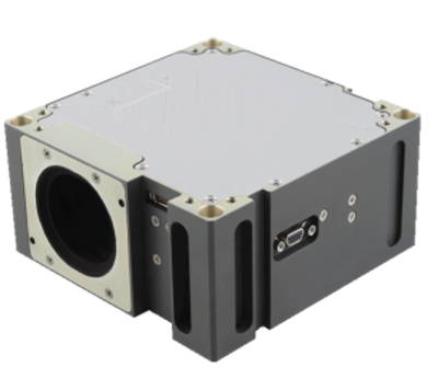
Integrated units combine multiple attitude and navigation components to provide a simple, single-component solution to spacecraft GNC requirements. Typical components include reaction wheels, magnetometers, magnetic torquers, fine and/or coarse Sun sensors, GPS, and star trackers. The systems often include processors and software with attitude determination and control capabilities to support common mission profiles, including Sun tracking, inertial pointing, and Earth target tracking. In addition, providers such as Blue Canyon Technologies (BCT) and CubeSpace provide overall GNC design and simulation with their products to ensure mission objectives can be met within the desired orbit environment and hardware constraints of the integrated unit and spacecraft bus. Using these integrated units can increase overall mission success, as the included ADCS software is also high TRL. BCT’s XACT (Figure 5.1) flew on the NASA-led MarCO and ASTERIA missions, which were both 6U platforms, and has also flown on 3U missions (MinXSS was deployed from NanoRacks in February 2016). Table 5-2 describes integrated systems currently available with TRL values of 7-9.
| Table 5-2: Currently Available Integrated Systems | ||||||
|---|---|---|---|---|---|---|
| Manufacturer | Model | Mass (kg) | Actuators | Sensors | Processor | Pointing Accuracy |
| AAC Clyde Space Sweden | iADCS-200 | 0.470 | 3 reaction wheels 3 magnetic torquers | 1 star tracker, 1 IMU, Optionally high precision magnetometer and sun sensors | Yes | <1° |
| iADCS-400 | 1.7 | 3 reaction wheels 3 magnetorquers | 1 star tracker, 1 IMU, Optionally high precision magnetometer and sun sensors | Yes | <1° | |
| Arcsec Belgium | Arcus ADC | 0.715 | 3 reaction wheels 3 magnetic torquers | 1 star tracker, 3 gyros 6 photodiodes 3 magnetometers | Yes | 0.1° |
| Berlin Space Technologies Germany | IADCS-100 | 0.4 | 3 reaction wheels 3 magnetic torquers | 1 star tracker, 3 gyros, 1 magnetometer, 1 accelerometer | Yes | <<1 deg |
| Blue Canyon Technologies USA | XACT-15 | 0.885 | 3 reaction wheels 3 magnetorquers | 1-2 Star Trackers, 1-4 Sun Sensors, IMU, Magnetometer, GPS | Yes | 0.003/0.007° |
| XACT-50 | 1.230 | 3 reaction wheels 3 magnetorquers | 1-2 Star Trackers, 1-4 Sun Sensors, IMU, Magnetometer, GPS | Yes | 0.003/0.007° | |
| XACT-100 | 1.813 | 3 – 4 reaction wheels 3 magnetorquers | 1-2 Star Trackers, 1-4 Sun Sensors, IMU, Magnetometer, GPS | Yes | 0.003/0.007° | |
| Flexcore | † | 3 – 4 reaction wheels 3 magnetorquers | 1-2 Star Trackers, 1-4 Sun Sensors, IMU, Magnetometer, GPS | Yes | 0.002° | |
| CubeSpace Satellite Systems South Africa | CubeADCS | 0.26* | 3/4(Pyramid) x reaction wheels, 3 x Magnetorquers distributed or integrated with ADCS core (3U/6U only) | Up to 4 x FSS, 2 x EHS, 2 x STR, 2 x MGTM. All distributed | 5Hz | ~70 arcsec (3 sigma) † |
| *Mass may vary if actuators are integrated inside CubeADCS core. †Configuration dependent | ||||||
5.2.2 Reaction Wheels
Miniaturized reaction wheels can provide small spacecraft with three-axis precision pointing capability. Reaction wheels provide torque and momentum storage along the wheel spin axis, causing the spacecraft to counter-rotate about its center of mass due to conservation of angular momentum from the wheel spin direction. For example, the spacecraft deployment process typically results in some tipoff momentum that can be observed as induced angular rates. This tipoff momentum can be stored in the reaction wheels, reducing the angular rate of the spacecraft to near zero. Reaction wheels must be carefully selected based on factors including the moment of inertia of the spacecraft, required momentum storage capacity, and mission slew rate requirements. Once a wheel reaches its maximum speed, it becomes saturated and can no longer provide torque or store momentum along that axis. To prevent this, reaction wheels need to be periodically desaturated using an actuator that provides an external torque, such as thrusters or magnetic torquers (7). By providing an external torque in an opposing direction, the reaction wheel compensates and spins down to keep the spacecraft at its target state (8).
While one or two reaction wheels can be used for a momentum-biased spacecraft, a full three-axis controlled spacecraft requires three wheels mounted orthogonally. As reaction wheel failure is a common failure mode in many missions, it is common to include three additional wheels as a hot backup (8). On smaller spacecraft where SWaP requirements prohibit redundant reaction wheels, a four-wheel configuration is often used to provide fault tolerance (9). The multiple reaction wheels are often assembled in a “skewed” or angled configuration such that there exists cross-coupled torques across two or more reaction wheels. While this reduces the torque performance in any single axis, it allows reduced but redundant torque capability across multiple axes. The result is that should any single reaction wheel fail, one or more reaction wheels are available as a reduced-capability backup option.
Though reaction wheels are typically the primary choice for precision three-axis pointing, other important considerations must be addressed. For example, they can introduce major attitude disturbances through static and dynamic imbalances, which can generate undesired forces, torques, and moments. While placing reaction wheels near the spacecraft center-of-gravity can help minimize the force/torque effects, other disturbances are location-independent and careful design considerations must be made (8). Reaction wheels are typically not magnetically clean, whether they are in the electromagnetic controller for spinning the wheels or ferrous materials being used in the wheel rotor itself, so careful placement within the spacecraft bus is required. Wheels typically should be placed with sufficient separation from magnetometers or other sensitive instrumentation. As magnetic torquers are the primary method of preventing reaction wheel saturation for small spacecraft in Earth orbit, they require accurate measurements of the Earth’s magnetic field to determine torquer commands, making wheel placement especially critical in the spacecraft bus design (11). Another consideration is how the reaction wheel is used in orbit and the required pointing precision. Most reaction wheels have reduced performance around zero-crossings (transition between positive/negative speeds), so some missions choose to bias the momentum (e.g., wheels running at approximately half their maximum speed when at zero spacecraft angular rate) (12). This can provide finer control with less jitter at the expense of reduced overall momentum capacity (effectively half).
Table 5-3 lists a selection of high-heritage miniature reaction wheels. Except for three units, all listed reaction wheels have spaceflight heritage.
| Table 5-3: High Heritage Miniature Reaction Wheels | |||||||
|---|---|---|---|---|---|---|---|
| Manufacturer | Model | Mass (kg) | Peak Power (W) | Peak Torque (Nm) | Momentum Capacity (Nms) | # Wheels | Rad. Tol. (krad) |
| AAC Clyde Space Sweden | RW210 | 0.48 | 0.8 | 0.0001 | 0.006 | 1 | 36 |
| RW400 | 0.375 | 15 | 0.008 | 0.050 | 1 | 36 | |
| Trillian-1 | 1.5 | 24 | 47.1 | 1.2 | 1 | — | |
| Astrofein Germany | RW1 Type A | ≤ 0.025 | < 0.375 + PWDE | 23e-6 | 5.8e-4 | 1 | / |
| RW1 Type B | ≤ 0.012 | < 0.3 + PWDE | 4e-6 | 1.0e-4 | 1 | / | |
| RW25 | ≤ 0.2 | < 2.8 | 0.002 | 0.03 | 1 | / | |
| RW35 | ≤ 0.5 | ≤ 9 | 0.005 | 0.1 | 1 | 20 | |
| RW90 | ≤ 0.9 | ≤ 16.5 | 0.015 | 0.35 | 1 | 20 | |
| RW100 | ≤ 0.8 | ≤ 25 | 0.02 | 0.4 | 1 | 20 | |
| RW150 | ≤ 1.3 | ≤ 42 | 0.03 | 1 | 1 | 20 | |
| RWT150 | ≤ 1.5 | ≤ 120 | 0.1 | 1 | 1 | 20 | |
| RW250 | ≤ 2.75 | ≤ 100 | 0.1 | 4 | 1 | 20 | |
| RWT250 | ≤ 2.75 | ≤ 200 | 0.3 | 4 | 1 | 20 | |
| Berlin Space Technologies Germany | RWA05 | 1.700 | 23.5 | 0.016 | 0.5 | 1 | 30 |
| Blue Canyon Technologies USA | RWp015 | 0.130 | 5.5 | 0.004 | 0.015 | 1 | — |
| RWp050 | 0.240 | 9 | 0.007 | 0.050 | 1 | — | |
| RWp100 | 0.330 | 9 | 0.007 | 0.100 | 1 | — | |
| RWp500 | 0.750 | 25 | 0.025 | 0.500 | 1 | — | |
| RW1 | 0.950 | 100 | 0.07 | 1.000 | 1 | — | |
| RW4 | 3.200 | 204 | 0.250 | 4.000 | 1 | — | |
| RW8 | 4.400 | 204 | 0.250 | 8.000 | 1 | — | |
| RW16 | 7.5 | 204 | 0.25 | 16 | 1 | — | |
| Comat France | RW20 | 0.180 | 1 | 0.002 | 0.02 | 1 | 20* |
| RW40 | 0.230 | 1 | 0.004 | 0.04 | 1 | 20* | |
| RW60 | 0.275 | 1 | 0.006 | 0.06 | 1 | 20* | |
| CubeSpace Satellite Systems South Africa | CubeWheel CW0017 | 0.06 | 0.85 | 0.23 | 0.0017 | 1/3/4 (Pyramid) | 24 |
| CubeWheel CW0057 | 0.115 | 2.7 | 2 | 0.0057 | 1/3/4 (Pyramid) | 24 | |
| CubeWheel CW0162 | 0.144 | 7.2 | 7 | 0.0162 | 1/3/4 (Pyramid) | 24 | |
| CubeWheel CW0500 | 0.310 | 15 | 16 | 0.05 | 1/3/4 (Pyramid) | 24 | |
| CubeWheel CW1200 | 0.450* | 32 | 20 | 0.12 | 1/3/4 (Pyramid) | 24 | |
| CubeWheel CW2500 | 0.750* | 33 | 27 | 0.25 | 1/3/4 (Pyramid) | 24 | |
| CubeWheel CW5000 | 1.084 | 48 | 37 | 0.5 | 1/3/4 (Pyramid) | 24 | |
| CubeWheel CW10K | 2.1* | 50 | 37 | 1 | 1/3/4 (Pyramid) | 24 | |
| CubeWheel CW40K | 2.2* | 85 | 37 | 4 | 1/3/4 (Pyramid) | 24 | |
| GomSpace Denmark | NanoTorque GSW-600 | 0.940 | 0.3 | 0.0015 | 0.019 | 1 | — |
| NanoAvionics Lithuania | RWO | 0.137 | 3.25 | 0.0032 | 0.020 | 1 | 20 |
| 4RWO | 0.665 | 6 | 0.0059 | 0.037 | 4 | 20 | |
| NewSpace Systems South Africa | NRWA-T6 | <5 | 136 | 0.3 | 0.00783 | 1 | 20 |
| NRWA-T065 | 1.55 | 1.7 | 0.02 | 0.00094 | 1 | 10 | |
| NRWA-T2 | 2.8 | 0.4 | 0.09 | 0.00163 | 1 | 10 | |
| Rocket Lab USA | RW-0.03 | 0.185 | 1.8 | 0.002 | 0.040 | 1 | 20 |
| RW-0.003 | 0.048 | — | 0.001 | 0.005 | 1 | 10 | |
| RW-0.01 | 0.122 | 1.05 | 0.001 | 0.018 | 1 | 20 | |
| RW3-0.06 | 0.235 | 23.4 | 0.020 | 0.180 | 1 | 20 | |
| RW4-0.2 | 0.6 | — | 0.1 | 0.2 | 1 | 60 | |
| RW4-0.4 | 0.77 | — | 0.1 | 0.4 | 1 | 60 | |
| RW4-1.0 | 1.38 | 43 | 0.1 | 1 | 1 | 60 | |
| Space Inventor Denmark | WHL-100 | 0.35 | TBD | 20 | 100 | 1 | — |
| WHL-200 | 0.42 | TBD | 25 | 200 | 1 | — | |
| WHL-500 | 0.8 | TBD | 50 | 500 | 1 | — | |
| WHL-1000 | 1.175 | 180 | 100 | 1000 | 1 | — | |
| WHL-12000 | 5.9 | — | 1200 | 12000 | 1 | — | |
| Vectronic Aerospace Germany | VRW-B-02 | 1 | 45 | 0.02 | 0.2 | 1 | 20 |
| VRW-C-05 | 1.2 | 65 | 0.05 | 0.6 | 1 | 20 | |
| VRW-C-1 | 2.3 | 65 | 0.05 | 1.2 | 1 | 20 | |
| VRW-D-1 | 1.9 | 65 | 0.05 | 1.2 | 1 | 20 | |
| VRW-D-16 | 1.8 | 65 | 0.05 | 1.6 | 1 | 20 | |
| VRW-D-2 | 2 | 65 | 0.05 | 2.0 | 1 | 20 | |
| VRW-D-27 | 2.45 | 65 | 0.05 | 2.7 | 1 | 20 | |
| VRW-D-4 | 2.5 | 65/110 | 0.05/0.09 | 4.0 | 1 | 20 | |
| VRW-D-6 | 3 | 65/110 | 0.05/0.09 | 6.0 | 1 | 20 | |
| VRW-D-8 | 3.5 | 110 | 0.09 | 8.0 | 1 | 20 | |
| VEOWARE Belgium | WHL-100 | 0.35 | — | 0.02 | 0.1 | 1 | — |
| WHL-200 | 0.43 | — | 0.025 | 0.2 | 1 | — | |
| WHL-500 | 0.8 | — | 0.5 | 0.5 | 1 | — | |
| WHL-100 | 1.2 | — | 0.1 | 1 | 1 | — | |
| *Printed Circuit Board (PCB) level | |||||||
5.2.3 Magnetic Torquers
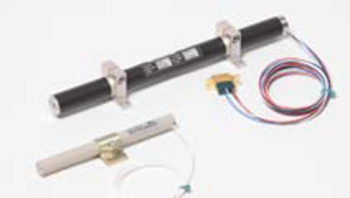
Magnetic torquers provide control torques perpendicular to the local external magnetic field. They are divided into two categories and are usually labeled as air coils or torquer bars/rods. Both operate by applying an electric current through a coiled conductor, generating a magnetic dipole through the center of the coil that loops around itself (8). This generated magnetic dipole interacts with the local external magnetic field, generating a torque perpendicular to the dipole and the field. The strength of the dipole, and thereby the torque, is governed by the area of the coil and the number of turns in the coil. For torquer bars/rods, a ferrous core is added, which greatly amplifies the strength of the magnetic field without an increase in required power consumption. While these bars/rods typically provide volume and power savings, the ferrous material can hold a residual field even when the device is powered off, which can affect other sensitive instrumentation such as magnetometers. With air coils, however, residual magnetic fields dissipate very rapidly when powered off. Air coils typically need a larger coil radius and/or more windings with higher power consumption to provide an equivalent magnetic dipole as compared to torquer bars/rods. Many are custom designed specifically for the mission’s spacecraft bus, such as being integrated into a components PCB inner layer. As such, fewer providers offer them as COTS components. Table 5-4 lists a selection of high-heritage magnetic torquers and Figure 5.3 illustrates some of ZARM Technik’s product offerings.
As control torques can only be provided in the plane perpendicular to the local magnetic field and generated magnetic dipole, magnetic torquers alone cannot typically provide three-axis stabilization. A spacecraft will typically have three magnetic torquers mounted on orthogonal axes, and there is usually no need for redundant torquers because the electro-mechanical design provides internal redundancy (8). Some research shows that coarse three-axis pointing can be achieved, but this requires multiple orbits and sufficient orbit inclination to provide external magnetic field variability. Typically, magnetic torquers are used to remove excess momentum from reaction wheels. As the torque generated by magnetic torquers acts externally to the spacecraft, the reaction wheels apply an internal counter torque to compensate and reduce their stored momentum. Magnetic torquers are also used on spinner missions, where they can slowly spin up the spacecraft by applying an external torque over time.
Use of magnetic torquers beyond low-Earth orbit and in interplanetary applications needs to be carefully investigated since their successful operation is dependent on a significant local external magnetic field. This magnetic field may or may not be available in the location and environment of a given mission, and additional control methods may be required.
| Table 5-4: High Heritage Magnetic Torquers | ||||||
|---|---|---|---|---|---|---|
| Manufacturer | Model | Mass (kg) | Power (W) | Peak Dipole (A m2) | # Axes | Rad Tol. (krad) |
| AAC Clyde SpaceSweden | MTQ800 | 0.395 | 3 | 15 | 1 | — |
| CubeSpace Satellite Systems South Africa | CubeTorquer CR0002 | 0.0165 | 0.49 | 0.2 | 1 | 24 |
| CubeTorquer CR0003 | 0.023 | 0.38 | 0.3 | 1 | 24 | |
| CubeTorquer CR0004 | 0.023 | 0.63 | 0.4 | 1 | 24 | |
| CubeTorquer CR0006 | 0.031 | 0.56 | 0.6 | 1 | 24 | |
| CubeTorquer CR0008 | 0.028 | 0.56 | 0.8 | 1 | 24 | |
| CubeTorquer CR0010 | 0.037 | 0.67 | 1 | 1 | 24 | |
| CubeTorquer CR0012 | 0.045 | 0.68 | 1.2 | 1 | 24 | |
| CubeTorquer CR0020 | 0.054 | 0.77 | 2 | 1 | 24 | |
| GomSpace Denmark | Nano Torque GST-600 | – | – | 0.31–0.34 | 3 | – |
| NanoTorque Z-axis Internal | 0.106 | – | 0.139 | 1 | – | |
| ISISPACE The Netherlands | Magnetorquer Board | 0.196 | 1.2 | 0.20 | 3 | – |
| MEISEI Japan | Magnetic Torque Actuator for Spacecraft | 0.5 | 1 | 12 | 1 | – |
| NanoAvionics Lithuania | MTQ3X | 0.205 | 0.4 | 0.30 | 3 | – |
| MTQ MP42 | 0.215 | 2.5 | 5 | 1 | ||
| NewSpace Systems South Africa | NCTR-M003 | 0.030 | 0.25 | 0.29 | 1 | – |
| NCTR-M012 | 0.053 | 0.8 | 1.19 | 1 | – | |
| NCTR-M016 | 0.053 | 1.2 | 1.6 | 1 | – | |
| Rocket Lab USA | TQ-40 | 0.825 | – | 48.00 | 1 | – |
| TQ-15 | 0.400 | – | 19.00 | 1 | – | |
| Space Inventor Denmark | MT-0,425 | 0.1 | 0.3 | 0.425 | 1 | – |
| MT-1 | 0.23 | 0.27 | 1 | 1 | – | |
| MT-2 | 0.375 | 0.25 | 2 | 1 | – | |
| ZARM Technik Germany** | MT0.2-1 | 0.012-0.014 | 0.135-0.25 | 0.2 | 1 | NA* |
| MT0.5-1 | 0.009 | 0.275 | 0.5 | 1 | NA* | |
| MT0.7-1-01 | 0.035 | 0.5 | 0.7 | 1 | NA* | |
| MT1-1-01 | 0.065 | 0.23 | 1 | 1 | NA* | |
| MT1.5-1-01 | 0.097 | 0.4 | 1.5 | 1 | NA* | |
| MT2-1-02 | 0.1 | 0.5 | 2 | 1 | NA* | |
| MT3-1-D22042701 | 0.15 | 0.7 | 3 | 1 | NA* | |
| MT4-1 | 0.15 | 0.6 | 4 | 1 | NA* | |
| MT5-1 | 0.19-0.3 | 0.73-0.75 | 5 | 1 | NA* | |
| MT5-2 | 0.31 | 0.77 | 5 | 1 | NA* | |
| MT6-2 | 0.25-0.3 | 0.48-1.1 | 6 | 1 | NA* | |
| MT7-2 | 0.4 | 0.9 | 7 | 1 | NA* | |
| MT10-1 | 0.35-0.4 | 0.53-0.8 | 10 | 1 | NA* | |
| MT10-2 | 0.37-0.48 | 0.7-1 | 10 | 1 | NA* | |
| MT15-1 | 0.4-0.55 | 1.0-1.55 | 15 | 1 | NA* | |
| * Only EEE parts are connector and wires. Magnetorquer is not sensitive to ionizing radiation. ** ZARM Technik: Over 200 models available with design to mass/power optimization. | ||||||
5.2.4 Thrusters
Thrusters can generate forces and torques, providing spacecraft with both attitude and translational control capabilities (8). As they are not dependent on external fields or dynamics, they can be used in any orbit. However, they require some type of expendable fuel source, so the thruster lifetime can be limited. While not typically employed on SmallSats for attitude control, recent advances propulsion miniaturization have enabled COTS availability. Thrusters have the advantage of providing large external torques for rapid maneuvers, quick reaction wheel desaturation, and spin stabilization. When used for attitude control, these systems can become more complex to mitigate induced translational dynamics.
When these propulsion systems are used to provide orbital and/or translational control, attitude control remains necessary to control the direction of thrust. Even with a full three degree-of-freedom thruster system, depending on the thruster configuration and the center of gravity of the spacecraft, thrusters can impart undesired torques that must be mitigated using attitude control systems such as reaction wheels or ACS thrusters.
One critical application of state-of-the-art thrusters is on proximity operations missions, an increasing area of focus for advanced mission concepts. Proximity operations require both high-precision translational and attitude control that typically cannot be achieved with other actuators. Further discussion is provided in Section 5.3.1. Translation and pointing accuracy are determined by minimum impulse bit and control authority by thruster force, with significant improvements made recently in this field. An in-depth discussion on thrusters for attitude and translational control is provided in Chapter 4: In-Space Propulsion.
5.2.5 Star Trackers
A star tracker can provide an accurate estimate of the absolute three-axis attitude by comparing a digital image to an onboard star catalog (9). Star trackers identify and track multiple stars and provide three-axis attitude solutions up to several times per second (8). While simple in concept, star trackers are among the most expensive small spacecraft components with a significant variance in capabilities between manufacturers. To operate, the sensor requires a clear field-of-view of a starfield such that an initial lost-in-space solution can be found. This initial acquisition depends on the FOV, magnitude of the stars, and the star tracker’s internal processing capabilities. Factors such as spacecraft angular rate, external light sources, and glare can corrupt and invalidate the solution. Missions dependent on accurate attitude information typically include IMU-propagated Kalman filter to maintain an attitude solution when the star tracker may lose the solution. Mission design and star tracker integration into the spacecraft bus also require careful geometry analysis to ensure that the FOV remains clear for critical mission operations. Missions with propulsion must also worry about contaminating the optics from thruster exhaust plumes.
While all COTS star tracker suppliers can provide a full state attitude solution, it is their accuracy and capabilities in difficult situations that distinguish the components and drastically increase their cost. Most modern star trackers can provide knowledge of the sensor’s boresight to within a few arcseconds, with reduced knowledge about the roll axis (8) when the spacecraft is inertially fixed. The accuracy is typically dependent on the optics’ FOV, the sensor’s resolution, and the processing power dictating the size of the star catalog. However, this accuracy can quickly degrade if the spacecraft has some angular rate. For example, cheaper star trackers might be able to track a solution at up to 0.3 deg/s spacecraft angular rates, whereas more expensive options may track up to 3.0 deg/s. Other factors such as stray light resilience, initial acquisition time, and precision also drive up costs. State-of-the-art developments focus on improving the speed and accuracy of the sensors, as well as decreasing their size and mass. These advancements have allowed new manufacturers to enter the field with lower-cost options, allowing missions to obtain full 3-axis attitude information with a sensor that would otherwise be cost-prohibitive. Table 5-5 lists some models suitable for use on small spacecraft. For example, Arcsec’s Sagitta Star Tracker was launched on the SIMBA CubeSat in 2020.
| Table 5-5: Star Trackers Suitable for Small Spacecraft | |||||||
|---|---|---|---|---|---|---|---|
| Manufacturer | Model | Mass (kg) | Power (W) | FOV | Cross axis Accuracy (1 or 3s) | Twist Accuracy (1 or 3s) | Rad. Tol. (krad) |
| Arcsec Belgium | Sagitta | 0.275 | 1.4 | 25.4° | 6 | 30 | 20 |
| Twinkle | 0.04 | 0.6 | 10.4° | 30 | 180 | – | |
| BAE Systems Inc, Space and Mission Systems USA | CT-2020 | 3.000 | 8 | – | 1.5” | 1” | – |
| Berlin Space Technologies Germany / AAC Clyde Space Sweden | ST200 | 0.040, 0.106* | 0.65 | 22° | 30″ | 200″ | 11 |
| ST400 | 0.250, 0.270* | 0.75 | 15° | 15″ | 150″ | 11 | |
| Blue Canyon Technologies USA | Standard NST | 0.350 | <1.5(5V) or <3.5(28V) | 10° x 12° | Gen 2: 6″ | Gen 2: 40″ | – |
| Full-Extension NST | 0.85 | <1.5(5V) or <3.5(28V) | 10° x 12° | Gen 2: 6 Gen 3: 1 | Gen 2: 40 Gen 3: 10 | ||
| Creare USA | UST | 0.840 | – | – | 7″ | 15″ | – |
| CubeSpace Satellite Systems South Africa | CubeStar | 0.047 | 0.271 | 59.4° | 0.02° | 0.06° | 24 |
| Danish Technical University Denmark | MicroASC | 0.425 | 1.9 | – | 2” | – | – |
| Jena-Optronik Germany | ASTRO CL | 0.305 | <1.0 | 25° full cone | 6″ | 48″ | 50 |
| ASTRO APS | ~2 | <6 (<12 w/ TEC) | 20° full cone | 3″ | 24″ | 100 | |
| ASTRO APS3 | 1.8 | <6 (<8 w/ TEC) | 20° full cone | 2.4″ | 21″ | 100 | |
| Leonardo Italy | Spacestar | 1.600 | 6 | 20° x 20° | 7.7″ | 10.6″ | – |
| NanoAvionics Lithuania | ST-1 | 0.108 | 1.2 | 21° full-cone | 8″ | 50″ | 20 |
| Redwire Space USA | Star Tracker | 0.475 | 2.5 | 14×19 | 10/27″ | 51″ | 75 |
| Rocket Lab USA | ST-16RT2 | 0.185 | 1 | 8° half-cone | 5″ | 55″ | – |
| Sodern France | Auriga-CP | 0.225 | 0.8 | 30° | 10” | 70” | 35 |
| Hydra-M | 1.4 | 0.7 | 22° | 3” | 30″ | 50 | |
| Hydra-TC | 1.6 | 9.5 | 23,6° | 3” | 30” | 50 | |
| Solar MEMS Technologies Spain | STNS | 0.14 | 1 | 12° | 40″ | 70″ | 20 |
| Space Inventor Denmark | ASTRO CL | 0.465 | 1.5 | 25° | 2 | 12 | 100 |
| Space Micro USA | MIST | 0.520 | 3 | 14.5° | 15″ | 105″ | 30 |
| µSTAR-100M | 1.800 | 5 | – | 15″ | 105″ | 100 | |
| µSTAR-200M | 2.100 | 8-10 | – | 15″ | 105″ | 100 | |
| µSTAR-200H | 2.700 | 10 | – | 3″ | 21″ | 100 | |
| µSTAR-400M | 3.300 | 18 | – | 15″ | 105″ | 100 | |
| Terma USA | T1 | 0.637 OH | 0.8 OH*, 2.5 | 20° circular | 3.0″ | 21″ | 55† |
| T3 | 0.45 (DPU) 0.330 | 2 | 20° circular | 3.2″ | 22″ | 35 | |
| Vectronic Aerospace Germany | VST-41MN | 0.7 – 0.9 | 2.5 | 14° x 14° | 27″ | 183″ | 20 |
| VST-68M | 0.470 | 3 | 14° x 14° | 7.5″ | 45″ | 20 | |
| *Mass includes Baffle. †SEE Immune | |||||||
5.2.6 Magnetometers
Magnetometers provide measurements of the local magnetic field, which can be used to provide a real-time estimate of two-axis attitude information (14). This requires that a well-modeled magnetic field model is available to reference the measured magnetic field (8). With a time history of magnetometer data, algorithms exist (such as Kalman filters) that can provide full-state attitude and rate knowledge from magnetometer-only measurements. Using other sources of unit vector measurements (e.g., Sun sensor for Sun vector knowledge) can provide real-time three-axis attitude information by using algorithms such as TRIAD and QUEST. In addition to attitude information, knowledge of the local magnetic field is required to determine the necessary dipole for magnetic torquers to produce a desired external torque on the spacecraft.
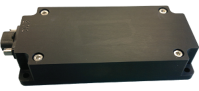
As a magnetometer cannot differentiate between sources of magnetic fields, placement on the spacecraft bus must be carefully considered. Sources such as reaction wheels and magnetic torquer rods can change the local magnetic field, as well as other sources of electromagnetic fields such as power systems, cabling harnesses, and even solar cells (8). Spacecraft with critical magnetic field measurement requirements may choose to place the magnetometer on a boom extending from the spacecraft, as magnetic dipole falls off at the inverse cube of distance. In addition to careful spacecraft placement, experience has shown that magnetometers may require on-orbit recalibration, which requires orbital position and preferably attitude data. Table 5-6 provides a summary of some three-axis magnetometers available for small spacecraft, one of which is illustrated in Figure 5.4.
| Table 5-6: Three-axis Magnetometers for Small Spacecraft | ||||||
|---|---|---|---|---|---|---|
| Manufacturer | Model | Mass (kg) | Power (W) | Resolution (nT) | Orthogonality | Rad Tolerance (krad) |
| AAC Clyde Space Sweden | MM200 | 0.012 | 0.01 | 1.18 | – | 30 |
| MAG-3 | 0.100 | Voltage Dependent | – | 1° | 10 | |
| CubeSpace Satellite Systems South Africa | CubeMag Deployable | 0.016 | 0.23 | 13 | 0.6 | 24 |
| CubeMag Compact | 0.006 | 0.23 | 25 | 0.6 | 24 | |
| Exobotics UK | XO-SENSE-MAG | 0.05 | < 0.01 | 13 | – | 150 |
| GomSpace Denmark | NanoSense M315 | 0.008 | – | – | – | – |
| MEISEI Japan | 3-Axis Magnetometer for Small Satellite | 0.220 | 1.5 | – | 1° | – |
| NewSpace Systems South Africa | NMRM-Bn25o485 | 0.085 | 0.75 | 8 | 1° | 10 |
| Space Inventor Denmark | IMU-P4 | 0.1 | — | 13 nT | — | — |
| ZARM Technik Germany | Analogue High-Rel Fluxgate Magnetometer FGM-A-75 | 0.33 | 0.75 W | ±75000 | 1° | 50 |
| Digital AMR Magnetometer AMR-D-100-EFRS485 | 0.18 | 0.3 W | ±100000 | 1° | – | |
5.2.7 Sun Sensors
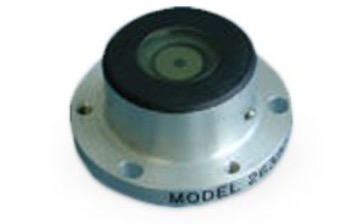
Sun sensors are used to estimate the direction of the Sun in a spacecraft body frame. Sun direction estimates can be used for attitude estimation, though to obtain a three-axis attitude estimate, at least one additional independent source of attitude information is required (e.g., the Earth nadir vector or the direction to a star). Because the Sun is easily identifiable and extremely bright, Sun sensors are often used for fault detection and recovery. However, care must be taken to ensure the Moon or Earth’s albedo does not inadvertently perturb the measurement. Even glint off nearby spacecraft components can corrupt measurements for certain Sun sensors types (8). One method to limit albedo effects is to exclude measurements below a certain brightness threshold (albedo is typically measured as a fraction of solar maximum), but care must be taken with this method as it may limit the effective field-of-view of the sensor (the cutoff threshold corresponds to the solar angle yielding the same cosine loss). Commercial examples of small spacecraft Sun sensors are described in Table 5-7.
There are several types of Sun sensors that operate on different principles.
Cosine detectors are photocells. Their output is the current generated by the cell, which is (roughly) proportional to the cosine of the angle between the sensor boresight and the Sun. Typically, several cosine detectors (pointing in different directions) are used on a spacecraft for full sky coverage. These sensors are the most susceptible to albedo effects. Cosine detectors (e.g., Figure 5.5) are inexpensive, low-mass, simple, and reliable devices, but their accuracy is typically limited to a few degrees, and they require analog-to-digital converters.
Quadrant detectors. Quadrant Sun sensors typically operate by shining sunlight through a square window onto a 2 x 2 array of photodiodes. The current generated by each photodiode is a function of the direction of the Sun relative to the sensor boresight. The measured currents from all four cells are then combined mathematically to produce the angles to the Sun. While more accurate than cosine detectors, they have a similar sensitivity to albedo effects.
Digital Sun Sensor. The Sun illuminates a narrow slit with a number of photodiodes located behind a geometrically coded bit mask. Depending on the angle to the Sun, the photodiodes will be illuminated as per the geometric pattern, resulting in correspondingly different photocurrents, which are then amplified and thresholded against an average value. Given the known slit geometries, this digital bit output can then be converted to a Sun angle.
Sun Camera. Some Sun sensors are built as small cameras that image the Sun. Since the Sun is so bright, the optics include elements to decrease the throughput. A computer identifies the image of the Sun and calculate the centroid. Sun sensors can be made very accurate this way and typically have built-in albedo rejection. Sometimes, multiple apertures are included to increase accuracy.
| Table 5-7: Commercial sun sensors | |||||||||
|---|---|---|---|---|---|---|---|---|---|
| Manufacturer | Model | Sensor Type | Mass (kg) | Peak Power (W) | Analog or Digital | FOV | Accuracy (3s) | # Measurement Angles | Rad. Tol. (krad) |
| AAC Clyde Space Sweden | SS200 | – | 0.003 | 0.04 | Digital | 110° | <1° | – | >36 |
| Berlin Space Technologies Germany | FSSA-110 | Fine Sun Sensor | With 3x sensor: 0.102 | 0.185 | Analog | 114° | 5° | ? | >20 |
| Bradford Space The Netherlands | CoSS | Cosine | 0.024 | 0 | Analog | 160° full cone | 3° | 1 | 40000 |
| CoSS-R | Cosine | 0.015 | 0 | Analog | 180° full cone | 3° | 1 | 120000 | |
| CSS | Cosine | 0.215 | 0 | Analog | 180°x180° | 1.5° | 2 | 70000 | |
| FSS | Quadrant | 0.375 | 0.25 | Analog | 128° x 128° | 0.3° | 2 | 100 | |
| Mini-FSS | Quadrant | 0.050 | 0 | Analog | 128° x 128° | 0.2° | 2 | 20000 | |
| CubeSpace Satellite Systems South Africa | CubeSense | Camera | 0.015 | 0.174 | Digital | 0.2° | 2 | 24 | – |
| GomSpace Denmark | NanoSense FSS | Quadrant | 0.002 | – | Digital | 45°, 60° | ±0.5°, ±2° | 2 | – |
| Lens R&D The Netherlands | BiSon64-ET | Quadrant | 0.023 | 0 | Analog | ±58° per axis | 0.5° | 2 | 9200 |
| BiSon64-ET-B | Quadrant | 0.033 | 0 | Analog | ±58° per axis | 0.5° | 2 | 9200 | |
| MAUS | Quadrant | 0.014 | 0 | Analog | ±57° per axis | 0.5° | 2 | 9200 | |
| Needronix Slovakia | Eagle | Fine Sun Sensor (±55°) | 0.003 | <0.007 | Digital | 110° | < ±0.15° | 2 plus Irradiation and Gyro | >20 |
| Eagle Plus | Fine Sun Sensor (±55°) | 0.005 | <0.015 | Digital | 110° | < ±0.1° | 2 plus Irradiation and Gyro | >20 | |
| Eagle Point | Fine Sun Pointing (±5.5°) | 0.006 | <0.015 | Digital | 11° | < ±0.01° | 2 plus Irradiation and Gyro | >20 | |
| Swan | Coarse Sun Sensor Pyramid | 0.070 | 0 | Analog | 170° (~ 2π Steradian) | < ±1° (Region I.) | 2 | >1000 | |
| NewSpace Systems South Africa | NFSS-411 | – | 0.035 | 0.150 | Digital | 140° | 0.1° | — | 20 |
| NCSS-SA05 | – | 0.005 | 0.05 | Analog | 114° | 0.5° | — | – | |
| Redwire Space USA | Coarse Analog Sun Sensor | Coarse Analog Sun Sensor | 0.045 | 0 | Analog | ±40° | ±1° | 1 | >100 |
| Coarse Sun Sensor (Cosine Type) | Coarse Sun Sensor (Cosine Type) | 0.010 | 0 | Analog | ~ Cosine, Conical Symmetry | ±2° to ±5° | Configuration dependent | >100 | |
| Coarse Sun Sensor Pyramid | Coarse Sun Sensor Pyramid | 0.13 | 0 | Analog | 2π steradian+ | ±1° to ±3° | 2 | >100 | |
| Digital Sun Sensor (±32°) | Digital Sun Sensor (±32°) | Sensor 0.3 kg Electronics ~1 | 1 | Digital | ±32° x ±32° (each sensor) | ±0.125° | 2 | 100 | |
| Digital Sun Sensor (±64°) | Digital Sun Sensor (±64°) | Sensor0.25 Electronics 0.29 – 1.1 | 0.5 | Digital | 128° X 128° (each sensor) Note: 4π steradians achieved with 5 sensors | ±0.25° | 2 | 100 | |
| Fine Pointing Sun Sensor | Fine Pointing Sun Sensor | Sensor .95 Electronics 1.08 | < 3 | Digital | ±4.25° x ±4.25° (Typical) | Better than ±0.01° | 2 | 100 | |
| Fine Spinning Sun Sensor (±64°) | Fine Spinning Sun Sensor (±64°) | Sensor 0.109 Electronics 0.475 – 0.725 | 0.5 | Analog and Digital | ±64° Fan Shaped (each sensor) | ±0.1° | 1 plus Sun Pulse | 100 | |
| Micro Sun Sensor | Micro Sun Sensor | < 0.002 | < 0.02 | Analog | ± 85° Minimum | ±5° | 2 | ~10 | |
| Miniature Spinning Sun Sensor (±87.5°) | Miniature Spinning Sun Sensor (±87.5°) | < 0.25 | 0.5 | Digital | ±87.5° (From normal to spin axis) | ±0.1° | 1 plus Sun Pulse | 100 | |
| Fine Sun Sensor (±50°) | Fine Sun Sensor (±50°) | – | – | Digital | 100 X 100 Each Sensor | ±0.01° TO ±0.05° | 2 | 100, 150, or 300 | |
| Solar MEMS Technologies Spain | nanoSSOC-A60 | Orthogonal | 0.004 | 0.007 | Analog | ±60° per axis | 0.5° | 2 | 100 |
| nanoSSOC-D60 | Orthogonal | 0.007 | 0.076 | Digital | ±60° per axis | 0.5° | 2 | 30 | |
| SSOC-A60 | Orthogonal | 0.025 | 0.01 | Analog | ±60° per axis | 0.5° | 2 | 100 | |
| SSOC-D60 | Orthogonal | 0.035 | 0.315 | Digital | ±60° per axis | 0.5° | 2 | 30 | |
| ACSS | Quadrant & Redundant | 0.035 | 0.072 | Analog | ±60° per axis | 0.5° | 2 | 200 | |
| Space Inventor Denmark | FSS | Quadrant | 0.01 | 0.1 | Digital | 55° half-cone | < 3 deg | 2 | – |
| Space Micro USA | CSS-01, CSS-02 | Cosine | 0.010 | 0 | Analog | 120° full cone | 5° | 1 | 100 |
| MSS-01 | Quadrant | 0.036 | 0 | Analog | 48° full cone | 1° | 2 | 100 | |
5.2.8 Horizon Sensors
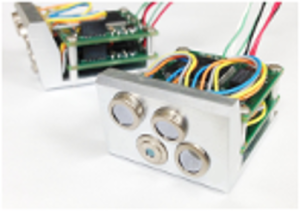
Horizon sensors can be simple infrared horizon-crossing indicators (HCI) or more advanced thermopile sensors that can detect temperature differences between the poles and equator. The sensors are typically either static or scanning, but by characterizing horizon crossings over a series of measurements, the sensors can provide an accurate nadir vector, which can then be used for attitude determination and/or attitude control guidance (8). For terrestrial applications, these sensors are referred to as Earth sensors, but they can be used for other planets. Examples of such technologies are described in Table 5-8 and shown in Figure 5.6.
In addition to the commercially available sensors listed in Table 5-8, there has been recent academic interest in horizon sensors for CubeSats with promising results (4)(15)(16).
| Table 5-8: Commercially Available Horizon Sensors | ||||||||
|---|---|---|---|---|---|---|---|---|
| Manufacturer | Model | Sensor Type | Mass (kg) | Peak Power (W) | Analog or Digital | Accuracy | # Measurement Angles | Rad. Tol. (krad) |
| CubeSpace Satellite Systems South Africa | CubeSense Earth | Infrared camera | 0.018 | 0.28 | Digital | 1° | – | 24 |
| Servo USA | Mini Digital HCI | Pyroelectric | 0.050 | Voltage Dependent | Digital | 0.75° | — | — |
| RH 310 HCI | Pyroelectric | 1.5 | 1 | — | 0.015° | — | 20 | |
| Solar MEMS Technologies Spain | HSNS | Infrared | 0.120 | 0.150 | Digital | 1° | 2 | 30 |
5.2.9 Inertial Sensing
Inertial sensors include gyroscopes for measuring angular change and accelerometers for measuring velocity change. They are packaged in different ways that range from single-axis devices (e.g., a single gyroscope or accelerometer) to packages that include three orthogonal axes of gyroscopes (Inertial Reference Unit (IRU)), to units containing three orthogonal gyros and three orthogonal accelerometers (Inertial Measurement Unit (IMU)). These sensors are frequently used to propagate the vehicle state between measurement updates from non-inertial sensors. For example, star trackers typically provide attitude updates at a few Hertz. If the control system requires accurate knowledge between star tracker updates, an IMU may be used for attitude propagation over that interval.
Gyroscope technologies typically used in modern small spacecraft are fiber optic gyros (FOGs) and MEMS gyros, with FOGs typically offering superior performance at a mass and cost penalty (18). While MEMS are smaller and can provide sufficient performance, they are more susceptible to radiation and single-event upsets, with radiation-hardened models only recently becoming available (8). Other gyroscope types exist (e.g., resonator gyros, ring laser gyros), but these are not common in the SmallSat/CubeSat world due to size, weight, and power (SWaP) and cost.
Gyro behavior is a complex topic (19), and gyro performance is typically characterized by a multitude of parameters. Table 5-9 only includes bias stability and angle random walk for gyros, and bias stability and velocity random walk for accelerometers, as these are often key performance parameters. That said, when selecting inertial sensors, it is important to consider other factors such as dynamic range, output resolution, bias, sample rate, etc. Factors such as turn-on bias and bias drift require onboard estimation of bias so that the sensor can be used in attitude determination and control systems.
| Table 5-9: Gyros Available for Small Spacecraft | |||||||||||||
|---|---|---|---|---|---|---|---|---|---|---|---|---|---|
| Manufacturer | Model | Sensor Type | Technology | Mass (kg) | Power (W) | Gyros | Accelerometers | ||||||
| Bias Stability | ARW | Bias Stability | VRW | ||||||||||
| # Axes | (°/hr) | stat | (°/rt(hr)) | # Axes | (µg) | stat | (m/sec)/rt(hr) | ||||||
| Emcore USA | QRS11 | Gyro | MEMS | ≤0.06 | 0.8 | 1 | 6 | Typical | – | – | – | – | – |
| QRS28 | Gyro | MEMS | ≤0.025 | 0.5 | 2 | – | – | – | – | – | – | – | |
| Honeywell USA | MIMU | IMU | RLG | 4 | 34 | 3 | 0.05 | – | 0.01 | – | 100 | – | – |
| HG1700 | IMU | RLG | 0.9 | 5.000 | 3 | 1.000 | 1s | 0.125 | 3 | 1000 | 1s | 0.65 | |
| HG4934SRS (68904934-BA60) | IRU | MEMS | 0.145 | <5.500 peak | 3 | < 3.0 | 3s | <0.20 max | None, IRU only | None, IRU only | None, IRU only | None, IRU only | |
| L3 USA | CIRUS | Gyros | FOG | 15.400 | 40.000 | 3 | 0.000 | 1s | 0.100 | 0 | – | – | – |
| NewSpace Systems South Africa | NSGY-001 | IRU | Image-based rotation estimate | 0.055 | 0.200 | 3 | – | – | 0 | – | – | – | |
| Northrop Grumman USA | LN-200S | IMU | FOG, SiAc | 0.748 | 12 | 3 | 1.000 | 1s | 0.070 | 3 | 300 | 1s | – |
| NovAtel Canada | OEM-IMU-STIM300 | IMU | MEMS | 0.055 | 1.50 | 3 | 0.500 | — | 0.150 | 3 | 50 | – | 0.060 |
| Safran France | STIM202 | IRU | MEMS | 0.055 | 1.500 | 3 | 0.400 | — | 0.170 | 0 | – | – | – |
| STIM210 | IRU | MEMS | 0.052 | 1.500 | 3 | 0.300 | — | 0.150 | 0 | – | – | – | |
| STIM300 | IMU | MEMS | 0.055 | 2.000 | 3 | 0.300 | — | 0.150 | 3 | 50 | — | 0.07 | |
| STIM318 | IMU | MEMS | 0.057 | 2.500 | 3 | 0.300 | — | 0.150 | 3 | 3 | — | 0.015 | |
| STIM320 | IMU | MEMS | 0.057 | 2.500 | 3 | 0.300 | — | 0.100 | 3 | 3 | — | 0.015 | |
| STIM277H | IRU | MEMS | 0.052 | 1.500 | 3 | 0.300 | — | 0.150 | 0 | – | — | – | |
| STIM377H | IMU | MEMS | 0.055 | 2.000 | 3 | 0.300 | — | 0.150 | 3 | 50 | — | 0.07 | |
| Silicon Sensing Systems UK | CRH03 | Gyro | MEMS | 0.42 | 0.2W | 1 | CRH03-010 – 0.03 CRH03-025 – 0.04 CRH03-100 – 0.04 CRH03-200 – 0.05 CRH03-400 – 0.1 | CRH03-010 – 0.005 CRH03-025 – 0.006 CRH03-100 – 0.006 CRH03-200 – 0.008 CRH03-400 – 0.010 | 0 | – | – | – | |
| CRH03 (OEM) | Gyro | MEMS | 0.18 | 0.2W | 1 | CRH03-010 – 0.03 CRH03-025 – 0.04 CRH03-100 – 0.04 CRH03-200 – 0.05 CRH03-400 – 0.1 | CRH03-010 – 0.005 CRH03-025 – 0.006 CRH03-100 – 0.006 CRH03-200 – 0.008 CRH03-400 – 0.010 | 0 | – | – | – | ||
| RPU30 | Gyro | MEMS | 1.35 | <0.8W | 3 | 0.06 | 0.006 | 0 | – | – | – | ||
| DMU41 | 9 DoF IMU | MEMS | <2 | <1.5W | 3 | 0.1 | 0.015 | 3 | 15 | – | 0.05 | ||
| CAS | Acc | MEMS | 0.004 | – | 0 | – | – | 2 | CAS2X1S – 7.5 CAS2X2S – 7.5 CAS2X3S – 7.5 CAS2X4S – 25 CAS2X5S – 75 | CAS2X1S – TBC CAS2X2S – TBC CAS2X3S – TBC CAS2X4S – TBC CAS2X5S – TBC | |||
| Space Inventor Denmark | IMU-P4 | MEMS | — | 0.15 | 0.2 | — | 0.3 deg/hr | — | 0.15 mm/s2 | 30 mm/s(hr) | |||
| VectorNav USA | VN-100* | IMU + magnetometer +barometer | MEMS | 0.015 | 0.220 | 3 | 10.000 | max | 0.210 | 3 | 40 | max | 0.082 |
| VN-110* | IMU + magnetometer | MEMS | 0.125 | 2.500 | 3 | 1.000 | max | 0.0833 | 3 | 10 | max | 0.024 | |
| *Small form-factor versions of these products available. — Represents unknown data | |||||||||||||
5.2.10 GPS Receivers
For low-Earth orbit spacecraft, GPS receivers are now the primary method for performing orbit determination, replacing ground-based tracking methods. Onboard GPS receivers are now considered a mature technology for small spacecraft; examples are listed in Table 5-10. There are also next-generation chip-size COTS GPS solutions; for example, the NovAtel OEM 719 board has replaced the ubiquitous OEMV1.
By measuring the time of arrival of signals from multiple GPS spacecraft, the GPS receiver can determine its position to a high degree of accuracy (8). A minimum of four spacecraft must be visible to the GPS receiver, of which three provide position data and a fourth provides timing to correct the GPS receiver’s clock bias. With multiple GPS antennas, a spacecraft’s GPS receiver can be used for attitude determination using phase differences in GPS signals, though the accuracy of this method is limited and prone to errors. GPS accuracy is limited by propagation variability through the exosphere and the underlying precision of the civilian-use C/A code (20). GPS units are controlled under the Export Administration Regulations (EAR) and must be licensed to remove COCOM limits (21).
Although the usability of GPS is limited to LEO missions, past experiments have demonstrated the ability to use weak GPS signals at GSO, and potentially at cislunar distances (23)(22). Development and testing in this rapidly growing field may soon make onboard GPS receivers more widely available.
| Table 5-10: GPS Receivers for Small Spacecraft | |||||
|---|---|---|---|---|---|
| Manufacturer | Model | Mass (kg) | Power (W) | Accuracy (m) | Rad. Tol. (krad) |
| AAC Clyde Space Sweden | GNSS-701 | 0.16 | — | < 5 | 10 |
| APL USA | Frontier Radio Lite | 0.4 | 1.4 | 15 | 20 |
| Aerospacelab Belgium | GNSS-VSP | 0.394 | 2.4 | 1.5 (RMS) | – |
| General Dynamics USA | Explorer | 1.2 | 8 | 15 | – |
| Viceroy-4 | 1.1 | 8 | 15 | – | |
| GomSpace Denmark | 0.285 | 3 | < 10 | < 20 | 0.285 |
| NovaTel Canada | OEM 719 | 0.031 | 0.9 | – | – |
| SENyT Argentina | Q Series | 0.14 | 2 | < 3 | – |
| Septentrio Belgium | AsteRx-m3 ProBase | 0.0027 | 1 | 0.0013 | – |
| SkyFox Labs Czech Republic | piNAV-NG | 0.024 | 0.124 | 10 | 30 |
| Space Inventor Denmark | GNSS-3 | 0.1 | 0.2 | 2 (CEP)* | – |
| Mosaic-T | 0.0068 | 0.6 | 1.2, 1.9 | – | |
| AsteRx SBi3 Pro+ | 0.49 | 1.5 | 1.2, 1.9 | – | |
| Spacemanic Czech Republic | Celeste GNSS | 0.025 | 0.25 | 2 (CEP)* | – |
| Surrey Satellite Technology UK | SGR-Ligo | 0.09 | 0.5 | 5 | 5 |
| U‑blox Switzerland | ZED‑F9P-05B | 0.0018 | 0.01 | 1.5, 2.25 | – |
| *Circular Error Probable | |||||
5.2.11 Deep Space Navigation
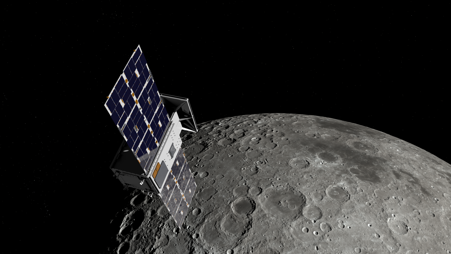
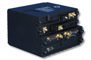
In deep space, navigation is performed using radio transponders in conjunction with the Deep Space Network (DSN). As of 2020, the only deep space transponder with flight heritage suitable for small spacecraft was the JPL-designed, and General Dynamics-manufactured Small Deep Space Transponder (SDST). JPL has also designed IRIS V2, which is a deep space transponder that is better suited to the CubeSat form factor. Table 5-11 details these two radios, and the SDST is shown in Figure 5.7. IRIS V2, derived from the Low Mass Radio Science Transponder (LMRST), has flown on the MarCO CubeSats in 2018, LICIACube, which performed an asteroid flyby in September 2022, the 12U lunar CAPSTONE spacecraft that entered a lunar orbit November 13, 2022, and on six Artemis 1 secondary CubeSat payloads (Lunar Flashlight, LunaH-Map, ArgoMoon, CubeSat for Solar Particles, Biosentinel, and NEA Scout). It is also scheduled to fly on INSPIRE (24).
| Table 5-11: Deep Space Transponders for Small Spacecraft | |||||
|---|---|---|---|---|---|
| Manufacturer | Model | Mass (kg) | Rx Power (W) | Bands | Rad. Tol. (krad) |
| General Dynamics USA | SDST | 3.2 | 12.5 | X, Ka | 50 |
| Space Dynamics Laboratory USA | IRIS V2.1 | 1.1 | 10.3 | X, Ka, S, or UHF | 25 |
| Iris Radio V3 | 0.8 | 10 | Simultaneous Multi-band: X, Ka, S | 25 | |
5.2.12 Atomic Clocks
Atomic clocks have been used on larger spacecraft in low-Earth orbit for several years now; however, integrating them on small spacecraft is relatively new. Table 5-12 provides examples of commercially available atomic clocks and oscillators for SmallSats. The conventional method for spacecraft navigation is a two-way tracking system using ground-based antennas and atomic clocks. The time difference between a signal sent from a ground station and the spacecraft’s response can be used to determine the spacecraft’s location, velocity, and (using multiple signals) its trajectory. This is inefficient, as the spacecraft must wait for navigation commands from the ground station instead of making real-time decisions, and the ground station can only track one spacecraft at a time, because it must wait for the spacecraft to return a signal (25). In deep space navigation, the distances are much greater between the ground station and spacecraft, and the accuracy of the radio signals must be measured within a few nanoseconds.
More small spacecraft designers are developing their own atomic clocks and oscillators that are stable and properly synchronized for use in space. They are designed to fit small spacecraft for missions that are power- and volume-limited or require multiple radios.
| Table 5-12: Atomic Clocks and Oscillators for Small Spacecraft | ||||||
|---|---|---|---|---|---|---|
| Manufacturer | Model | Dimensions (mm) | Mass (kg) | Power (W) | Frequency Range (MHz) | Rad Tolerance (krad) |
| Bliley Technologies USA | Iris Series 1″x1″ OCXO for LEO | 19 x 11 x 19 | 0.016 | 1.5 | 10 -100 | 39 |
| Aether Series TCVCXO for LEO | 21 x 14 x 8 | – | 0.056 | 10 – 150 | 37 | |
| Microchip USA | Chip Scale Atomic Clocks (CSACs) | 41 x 36 x 12 | 0.035 | 0.12 | 10 | 20 |
| Safran Timing Technologies SA France | MO | 44 x 54 x 57 | 0.22 | 3.5 Nom 5.5 Max | 10 | 100 |
| mRO-50 | 51 x 51 x 20 | 0.080 | 0.4 Nom | 10 | 25 Min | |
| miniRAFS | 108 x 53 x 68 | 0.45 | < 12 Max | 60 and 10 | – | |
| LNMO | 50 x 50 x 30 | 0.1 | 1.5 Nom 2.5 Max | 5 – 40 | 100 | |
| *Q‑Tech Corporation USA | Class B+ Products Hybrid Crystal Clock Oscillators | 5×7 | – | – | – | – |
| – Represents unknown data *Company offers several options viable for Smallsats | ||||||
5.2.13 LiDAR
Over the last decade, Light Detection and Ranging (LiDAR) has been an emerging sensor type that matured via terrestrial applications (such as automotive systems) and is used in larger spacecraft capable of proximity operations, such as Orion. This type of sensor has applications for small spacecraft altimetry and relative navigation (e.g., Mars helicopter, rendezvous and docking, and formation flying). Table 5-13 lists examples of LiDAR systems with flight heritage.
| Table 5-13: LiDAR for Small Spacecraft | |||||
|---|---|---|---|---|---|
| Manufacturer | Model | Mass (kg) | Power (W) | Max Range (m) | Rad. Tol.(krad) |
| ASC USA | GSFL-4K (3D) | 3 | 30 | >1 km in altimeter mode | – |
| Garmin USA | Lidar Lite V3 | 0.022 | 0.7 | 40 | – |
| – Represents unknown data | |||||
5.3 Formation Flying, Rendezvous and Proximity Operations
Other GNC advances involve research on SmallSats performing precision formation flying (PFF) and on-orbit rendezvous and proximity operations (RPO). Many research papers have discussed methods to achieve these capabilities, and extravehicular free flyer missions have demonstrated this capability in the past few decades. To enable autonomous PFF and RPO missions, spacecraft require a suite of sensors to feed onboard navigation filters to determine relative positions and attitudes, complex guidance laws to maintain formations within constraints and prevent on-orbit conjunctions, as well as advanced actuation methods to control the relative states of the spacecraft. While some commercial sensors and actuators exist specifically for enabling PFF and RPO missions, current research and missions are leveraging novel hardware and methods to achieve these objectives using existing components.
To enable relative guidance and control, it is important to first estimate the relative position and velocity, as well as attitude, of the spacecraft. Relative navigation can be accomplished using hardware specifically designed for the task, such as LiDAR, or repurposed hardware. For example, the PY4 mission demonstrated on-orbit range measurements between two spacecraft using S-band radio modules, augmented with a GPS receiver on the anchor spacecraft, and a batch Kalman filter to determine the relative position vector of a target spacecraft to an accuracy of approximately 4 meters (28). A mission using vision-based systems was Seeker, a 3U CubeSat that was deployed in September 2019 and designed to demonstrate capabilities basic proximity operations capabilities with a path to inspection of crewed vehicles. Seeker used a COTS laser rangefinder combined with a COTS industrial camera that fed a convolutional neural network to estimate bearing to a non-cooperative client. While Seeker did not complete all of its planned maneuvers, many core technologies were successfully demonstrated (30). The CubeSat Proximity Operations Demonstration (CPOD) mission used an optics module with four imagers for relative ranging and target attitude determination but required priori knowledge and markers on the tracked spacecraft (31). Launched in 2023, NASA’s Starling mission used its commercial star trackers to feed an orbit estimation algorithm known as the Starling Formation-flying Optical eXperiment (StarFOX). StarFOX provided angles-only relative navigation of an object, demonstrating on orbit relative position knowledge with only 0.5% error relative to range using one or multiple observers (32). In 2025, R5 Spacecraft 7 used a COTS industrial-grade LiDAR to perform proximity operations with a Falcon 9 upper stage. These missions illustrate the complexity of the navigation problem, especially as much of it must be done autonomously without ground-based intervention to achieve the objectives of PFF and RPO missions.
Once the navigation system has converged, guidance laws are used to determine trajectories to achieve PFF and RPO objectives, as well as avoid conjunctions with nearby objects. While this field is primarily research-based and dependent on algorithms instead of hardware, there is some development in packaged software suites to enable PFF and RPO missions. The Autonomous Navigation, Guidance, and Control Software (autoNGC) suite is being developed by NASA Goddard Space Flight Center to enable autonomous operations when ground communications are limited or unavailable, a critical need for cis-lunar and deep space missions (33). Lockheed Martin, in collaboration with government and industry partners, is developing the 12U LINUSS platform that will eventually offer spacecraft upgrade and servicing capabilities, a service heavily dependent on PFF and RPO technologies (34). The mission tested Lockheed Martin’s Horizon Command & Control and Compass Mission Planning Software, which seeks to provide a software solution for various mission operations including PFF (35). It is expected that this field will grow with the continued increased interest in PFF and RPO missions and that demand for software suites with proven flight heritage will become more common.
While there have been multiple successful demonstrations of on-orbit relative navigation for missions conducting PFF and RPO objectives, many of these missions have experienced control system and actuator challenges. The Seeker mission experienced multiple failures with the thruster system likely related to a FPGA controller failure, resulting in the inability to thrust in multiple axes, causing the mission to not meet its minimum objective (30). CPOD attempted the characterization of low-power proximity operations technologies, however it was only able to demonstrate limited RPO and unable to complete the planned docking maneuvers before its mission ended June 2023. The CPOD mission experienced partial solar panel failures resulting in lower power margins that limited mission operations, and experienced a propulsion system anomaly that was most likely related to a plenum leak. Although, the mission was able to demonstrate both far- and near-field rendezvous and ingress maneuvers, achieving most of the mission objectives. The spacecraft ran out of fuel before completing some of these objectives, preventing execution of the docking procedure which was intended to use a magnetic actuator to dock the two spacecraft. The Lockheed Martin LINUSS mission also experienced a plenum leak and required continuous ground interventions by the development team to overcome the continual challenges experienced (34). The Starling swarm, which ended its initial mission in May 2024, experienced a leak in the propellant system and initially a sticky refill valve, though both anomalies were able to be resolved through ground operations (37). The mission was ultimately able to resume its in-train formation using thrusters to lower each swarm member’s altitude and let differential drag establish required separations, allowing the mission to continue conducting various experiments. Other missions had success using non-propulsive control techniques like drag separation for formation maintenance. The PY4 mission successfully used drag separation for both in-track and cross-track maneuvers by controlling each individual member’s attitude to create the requisite drag differential (38). While such missions are less prone to failure by not relying on a propulsion system, they are typically limited to far-field rendezvous and cannot achieve PFF or near-field RPO objectives like docking.
The complexity of PFF and RPO missions for SmallSats continues to challenge the hardware, software, and operational design; however, these challenges will continue to be addressed as more industry, government, and university entities become involved. The recent successes of SmallSat swarms employing PFF indicate they are key contributors to the advancement of space situational awareness (SSA), space traffic management (STM), and in-space servicing and manufacturing (ISAM). In addition to distributed spacecraft autonomy (DSA) technology maturation, rendezvous, proximity operations, and docking (RPOD) is another key capability required for future space operations. These operations include inspection, refueling, repair, PFF, sample collection, or debris remediation.
A key technology to implement SSA, STM, and ISAM operations is the development of reliable docking and attachment mechanisms. For SmallSats in particular, the ability to dock, attach, or capture another object, whether a mothership, a cooperative servicing spacecraft, an asteroid, or orbital debris, is essential to perform on-orbit operations. While docking mechanisms exist on larger spacecraft, that technology is impractical for SmallSats due to SWaP-C concerns. Therefore, recent years have seen a surge in research and development focused on lightweight, low‑complexity, and scalable attachment technologies for SmallSats. Additionally, docking and attachment research spans multiple disciplines such as mechanical engineering, robotics and control, materials science, and others. Commercial effort in applying docking mechanisms to assist deorbit maneuvers is described in the Deorbit Systems chapter, and robotic manipulation is discussed in the Structures, Materials, and Mechanisms chapter.
Ongoing efforts across NASA, other government agencies, industry, and academia are maturing RPOD technology. A commercial collaboration between Starfish Space and Impulse Space on the “Remora” mission that launched in December 2025 achieved fully autonomous RPO in LEO with just a single camera system and closed-loop GNC software, enabling autonomous rendezvous between two Impulse Mira LEO Express vehicles (40). University of North Dakota’s Rendezvous & Operations for Autonomous Docking and Servicing (UND ROADS) is a low-cost flight demonstration of two 3U CubeSats to achieve RPO and docking with centimeter-level accuracy via RF ranging and carrier-phase GNSS, featuring magnetic docking and predictive GNC algorithms (41). The two UND ROADS CubeSats were launched June 2025 and are still operational (42).
5.4 On the Horizon
In general, technological progress in guidance, navigation, and control is advancing quickly in automotive applications but is lagging slightly in the aerospace industry. Given the high maturity of existing GNC components, future developments in traditional GNC systems are focused on incremental improvements, such as decreases in mass and power, and increases in longevity and/or accuracy. This is especially true for GNC components designed for deep space missions that have only recently been considered for small spacecraft.
Other areas of focus that enhance GNC capabilities include autonomous formation flying for SmallSat constellations such as RPOD and position, navigation, and timing (PNT) technologies. Recent advances in PNT have been driven by rapid advances in inertial sensors, atomic clocks, and emerging magnetic navigation methods tailored for near‑Earth environments. Modern inertial measurement units are leveraging breakthroughs in micro‑ and nano‑fabrication, quantum sensing, and low‑drift architectures to achieve high precision independent of GNSS (43)(44). In parallel, atomic clock development—particularly compact optical and chip‑scale systems—continues to improve timing stability and resilience, enabling more accurate synchronization and robust PNT solutions for both terrestrial and space applications (45)(46). Complementing these technologies, magnetic navigation is becoming a viable GNSS alternative or augmentation layer, using Earth’s geomagnetic signatures and real‑time field models to support navigation in GNSS‑degraded or denied regions. Together, these maturing capabilities are pushing PNT resilience and autonomy to new levels for near‑Earth missions and operational environments. Several projects funded via NASA’s Small Spacecraft Distributed Systems (SSDS, formerly Small Spacecraft Technology) program through the University SmallSat Technology Partnerships (USTP) initiative are advancing GNC systems. Listed below in Table 5-14 are projects that focus on GNC advancements, and further information can be found at the USTP website:
https://www.nasa.gov/smallspacecraft/university-smallsat-technology-partnership-initiative
| Table 5-14: USTP Initiative GNC Projects | |||
|---|---|---|---|
| Project | University | Current Status | Reference |
| DESPINA: X-Ray spectrometer optimized for deep space PNT using pulsar and other astrophysical X-ray sources | University of Minnesota | Still in development | (47) |
| ODIN: OPNAV instrument for deep space navigation | Georgia Institute of Technology | Still in development | (47) |
| High-TRL optical frequency combs (OFC) that enable planar on-chip navigation-grade oscillators with significantly better noise performance | California Institute of Technology | Still in development | (47) |
| On-Orbit Demonstration of Surface Feature-Based Navigation and Timing | University of Texas, Austin | Still in development | USTP Technology Expo presentation |
| Autonomous Nanosatellite Swarming (ANS) using Radio Frequency and Optical Navigation | Stanford University | Onboard Starling mission (Launched in 2023) | USTP Technology Expo presentation |
| Distributed multi-GNSS Timing and Localization (DiGiTaL) | Stanford University | Leveraged technology for ANS in Starling mission | USTP Technology Expo presentation |
| Mems Reaction Control and Maneuvering for Picosat beyond LEO | Purdue University | Awarded a suborbital flight test through NASA’s Flight Opportunities program | (29) |
| A Small Satellite Lunar Communications and Navigation System | University of Boulder, Colorado | Still in development | USTP Technology Expo presentation |
| A high-precision continuous-time PNT compact module for the LunaNet small spacecraft | University of California, Los Angeles | Still in development | USTP Technology Expo presentation |
5.5 Summary
Conventional small spacecraft GNC technology is a mature area, with many high TRL components previously flown in Earth orbit and offered by several vendors. These GNC techniques are generally semi- or non-autonomous as on-board observations are collected with the assistance of ground-based support. As interest in deep space exploration with small spacecraft grows, semi- to-fully-autonomous navigation methods must advance. It is likely that future deep space navigation will rely solely on fully autonomous GNC methods that require no ground-based intervention to collect and provide navigation data. This is a desirable capability as the spacecraft’s dependence on Earth-based tracking resources (such as DSN) is reduced and the demand for navigation accuracy increases at large distances from Earth. The success of the Starling mission in performing PFF reliably without external commands has paved the way for future DSN-independent solutions.
Current methods advancing deep space navigation involve both ground- and space-based tracking in conjunction with optical navigation techniques. To support this maturity, the small spacecraft industry has seen a rapid progression in PNT technologies, including inertial sensors, optical accelerometers, atomic clocks, and magnetic navigation for near-Earth environments. Advancements in RPOD technologies hold exciting implications for the future and will likely lead to growth in the SmallSat industry.
The rising popularity of SmallSats in general, and CubeSats in particular, means there is high demand for components, and engineers are often faced with high costs. The challenges that inhibited SmallSat engineers from achieving desired GNC/ADCS solutions a decade ago are less significant. There exists a multitude of best practices for assembling inexpensive and reliable attitude determination and navigation systems.
For feedback solicitation, please email: arc-sst-soa@mail.nasa.gov. Please include a valid business email so someone may contact you further.
References
- L.C.G Shepherd. and A.F.S.C Shepherd. “Space Surveillance Network.” Shared Space Situational Awareness Conference. Colorado Springs. 2006.
- D. Vallado, P. Crawford, R. Hujsak and T.S. Kelso. “Revisiting Spacetrack Report #3,” AIAA 2006-6753. AIAA/AAS Astrodynamics Specialist Conference and Exhibit. August 2006.
- Thornton, C L and Border, J S: “Radiometric Tracking Techniques for Deep-Space Navigation.” s.l: John Wiley & Sons, 2003.
- K. Kapás, T. Bozóki, G. Dálya et al. “Attitude determination for nano-satellites – I. Spherical projections for large field of view infrasensors.” Exp Astron 51, 515–527, 2021.
- JPL. “MarCO,” [Online] Available at: https://www.jpl.nasa.gov/missions/mars-cube-one-marco/
- J.R. Wertz. “Spacecraft attitude determination and control.” Springer Science & Business Media. Vol. 73. 2012.
- R. Kulczycki and P. Wisniewski. “Slew Maneuver Control for Spacecraft Equipped with Star Camera and Reaction Wheels.” 2005. Vol. 13, no. 3, pp. 349–356.
- J. L. Crassidis. “Spacecraft attitude determination.” Encyclopedia of systems and control. 2021, Cham: Springer International Publishing. 2097-2104.
- B.B. Spratling and D. Mortari. ““A survey on star identification algorithms.” 2009.
- Jin, J, Ko, S and Ryoo, C K: “Fault Tolerant Control for Satellites with Four Reaction Wheels.” 2008. Vol. 16, no. 10, pp. 1250–1258.
- M.G. Finley, R.M. Broadfoot, S. Shekhar, and D.M. Miles. “Identification and removal of reaction wheel interference from in-situ magnetic field data using multichannel singular spectrum analysis.” 2023. Journal of Geophysical Research: Space Physics, 128, e2022JA031020. https://doi.org/10.1029/2022JA031020
- U. P. Sampaio, A. St-Amour, J. Lafontaine. “Zero-Speed Crossing Avoidance with Three Active Reaction Wheels using Set-Point Angular Momentum Management,.” 2016. IFAC-PapersOnLine, Volume 49, Issue 17. Pages 135-140, ISSN 2405-8963, https://doi.org/10.1016/j.ifacol.2016.09.024
- C.C. Liebe, “Star Trackers for Attitude Determination,” IEEE Aerospace and Electronic Systems Magazine, vol. 10, no. 6, pp. 10-16, June 1995, doi: 10.1109/62.387971
- M.L. Psiaki, F. Martel, F and P.K. Pal. “Three-Axis Attitude Determination Via Kalman Filtering of Magnetometer Data.” Vol. 13, no. 3, pp. 506–514. 1990.
- J.H. Wessels. “Infrared Horizon Sensor for CubeSat Implementation.” Master’s Thesis, Stellenbosch University. March 2018.
- A. Pelemeshko et al. “High-Precision CubeSat Sun Sensor Coupled with Infrared Earth Horizon Detector.” 2020. IOP Conf. Ser.: Mater. Sci. Eng. Vol. 734. pp. 0121-8.
- M. M. Kobayashi et al. “The Iris Deep-Space Transponder for the SLS EM-1 Secondary Payloads.” IEEE Aerospace and Electronic Systems Magazine, vol. 34, no. 9, pp. 34-44, 1 Sept. 2019.
- D. Greenheck et al. “Design and Testing of a Low-Cost MEMS IMU Cluster for SmallSat Applications.” 28th Annual AIAA/USU Conference on Small Satellites, 2014.
- S. Merhav. “Aerospace Sensor Systems and Applications.” Springer New York, 1998.
- O. Montenbruck et al. “Precision Spacecraft Navigation Using a Low-Cost GPS Receiver.” 2014. Vol. 16, no. 4, pp. 519–529.
- “Foreign Availability Determination Procedures and Criteria.” 2015. Office of the Federal Register. Title 15 Part 768.7.
- A. Hadhazy. “Cosmic GPS.” Aerospace America. [Online] May 2020. Available at: https://aerospaceamerica.aiaa.org/features/cosmic-gps/
- J. Foust: “GPS in Space.” MIT Technology Review. [Online] January 2002. https://www.technologyreview.com/2002/01/01/275613/gps-in-space/
- F.H. Aguirre. “X-Band Electronics for The INSPIRE CubeSat Deep Space Radio.” 2015. IEEE Aerospace Conference.
- D. Baird. “NASA Tests Atomic Clock for Deep Space Navigation.” [Online] 2018. Available at: https://www.jpl.nasa.gov/news/news.php?feature=7053
- J.W Kolar et al. “High-Speed Magnetically Levitated Reaction Wheels for Small Satellites.” Anacapri, Capri: 23rd International Symposium on Power Electronics, Electrical Drives, Automation and Motion (SPEEDAM 2016), 2016.
- A.G. Cofer. “Film Evaporation Mems Thruster Array for Micropropulsion.” Open Access Dissertations. 1106. 2014. Available at: https://core.ac.uk/download/pdf/220145833.pdf
- M. Holliday, R. Ticknor, R. Hunter, J. Stupl, P. Fisch, I. Sow, J. Willis, and Z. Manchester. “The PY4 Mission: A Low-Cost Demonstration of CubeSat Formation-Flying Technologies.” 2024. Weekend Session VIII: Advanced Technologies – Research & Academia 2, 38th Annual AIAA/USU Small Satellite Conference, Logan UT.
- Jill Davis, Henry Pernicka. “Proximity operations about and identification of non-cooperative resident space objects using stereo imaging.” 2019. Acta Astronautica, Volume 155, Pages 418-425, ISSN 0094-5765, https://doi.org/10.1016/j.actaastro.2018.10.033.
- S. M. Pedrotty, “Seeker Overview and Mission 1 Review– A New Development Approach for In-Space Inspectors.” 2021. [Online] Available at: https://www.nasa.gov/smallsat-institute/seeker-overview-and-mission-1-review–a-new-development-approach-for-in-space-inspectors
- J. Bowen, M. Villa, and A. Williams. “CubeSat based Rendezvous, Proximity Operations, and Docking in the CPOD Mission.” 2015. Weekend Session VIII: Advanced Technologies – Research & Academia 2, 29th Annual AIAA/USU Small Satellite Conference, Logan UT.
- J. Kruger, S. D’Amico, and S.S. Hwang. “Starling Formation-Flying Optical Experiment: Initial Operations and Flight Results.” 2024. Weekday Session 11: Advanced Technologies 2, 38th Annual AIAA/USU Small Satellite Conference, Logan UT.
- S. Hur-Diaz, B. Azimi, M. Romeo, A. Lionis, N. Stacey, R. Pritchett, G. Crum, and S. Semper. “Autonomous Navigation, Guidance, and Control Software in a Low SWaP Box.” 2024. Weekday Poster Session 5, 29th Annual AIAA/USU Small Satellite Conference, Logan UT.
- D. Barnhart, D. M. Shoemaker, E. T. King, T. Logue, and M. J. Lavis. “LM LINUSS™ – Lockheed Martin In-Space Upgrade Servicing System.” 2023. Weekday Session 9: Formation Flying and RPO, 37th Annual AIAA/USU Small Satellite Conference, Logan UT.
- Lockheed Martin. Horizon Command & Control (C2) and Compass Mission Planning Software. [Online] Available at: https://www.lockheedmartin.com/en-us/products/satellite-software.html
- I. A. Spiegal, B. Zhou, R. Goodloe, B. Fox, J. DiMatteo. “CubeSat Proximity Operations Demonstration (CPOD) Mission Results.” 2023. Weekday Session 9: Formation Flying and RPO, 37th Annual AIAA/USU Small Satellite Conference, Logan UT.
- T. Stevenson. “Flight Results and Lessons Learned From the Starling Propulsion System.” 2024. Weekday Session 7: Propulsion, 38th Annual AIAA/USU Small Satellite Conference, Logan UT.
- G. Falcone, J. B. Willis, Z. Manchester. “Propulsion-Free Cross-Track Control of a LEO Small-Satellite Constellation with Differential Drag.” 2023. Systems and Control, Electrical Engineering and Systems Science, Cornell University. Available at: https://arxiv.org/abs/2306.13844
- D. Dickinson. “NICER and SEXTANT demonstrate XNAV pulsar navigation system that may be used on Artemis.” 2020. [Online] Available at: https://skyandtelescope.org/astronomy-news/nasa-to-use-pulsar-navigation-for-deep-space-missions/
- Impulse Space. “Starfish Space Completes Autonomous Rendezvous and Proximity Mission in LEO with Impulse Space,” December 15, 2025, [Online] Available at: https://www.impulsespace.com/updates/starfish-space-completes-autonomous-rendezvous-and-proximity-mission-in-leo-with-impulse-space
- University of North Dakota, “ROADS Mission,” John D. Odegard School of Aerospace Sciences, [Online] Available at: https://aero.und.edu/space/operations-group/roads-mission.html
- B. Dubensky, “UND in Orbit,” February 11, 2026, [Online] Available at: https://knoxradio.com/2026/02/11/und-in-orbit/
- “Quantum PNT Breaks Out as DIU and DARPA Make GPS-Proof Nav Real,” The Relay, October 8, 2025, [Online] Available at: https://therelaymag.com/quantum-pnt-breaks-out-as-diu-and-darpa-make-gps-proof-nav-real
- M. Muradoglu and M.T. Johnsson et al. “Quantum-assured magnetic navigation achieves positioning accuracy better than a strategic-grade INS in airborne and ground-based field trials”, 2025, 2504.08167, https://arxiv.org/abs/2504.08167.
- Z. Luo and T. C. Briles et al. “A scalable infrastructure for strontium optical clocks with integrated photonics,”2026, 2604.03229, https://arxiv.org/abs/2604.03229.
- Tang, Z., Li, C., Zhang, X. et al. 1-MHz linewidth VCSEL enabled by monolithically integrated passive cavity for high-stability chip-scale atomic clocks. Light Sci Appl 15, 94 (2026). https://doi.org/10.1038/s41377-026-02192-x
- National Aeronautics and Space Administration, “NASA Selects Universities to Support Small Spacecraft Technologies,” December 8, 2023, https://www.nasa.gov/directorates/stmd/small-spacecraft-technology-program/nasa-selects-universities-to-support-small-spacecraft-technologies/