


Chapter Contents
- Chapter Glossary
- 11.1 Introduction
- 11.2 Ground Systems Architecture
- 11.3 Frequency Considerations
- 11.4 Ground Segment Services
- 11.5 Ground Stations Components
- 11.6 Mission and Science Operations Centers
- 11.7 End-to-End Communications and Compatibility Testing
- 11.8 Cyber Security
- 11.9 State-of-the-Art – Ground Data and Supporting Systems
- 11.10 On the Horizon
- 11.11 Summary
- References
Chapter Glossary
| (API) | Application Programming Interface | |
| (AWS) | Amazon Web Services | |
| (C2) | Command & Control | |
| (CCSDS) | Consultative Committee for Space Data Systems | |
| (CFDP) | CCSDS File Delivery Protocol | |
| (DSN) | Deep Space Network | |
| (DTE) | Direct-to-Earth | |
| (DVB-S2) | Digital Video Broadcast Satellite Second Generation | |
| (EGSE) | Electrical Ground Support Equipment | |
| (EIRP) | Effective Isotropic Radiated Power | |
| (ESA) | European Space Agency | |
| (ESOC) | European Space Operations Centre | |
| (FCC) | Federal Communications Commission | |
| (GEO) | Geosynchronous Equatorial Orbit | |
| (GNSS) | Global Navigation Satellite System | |
| (GPS) | Global Positioning System | |
| (GSaaS) | Ground Segment as a Service | |
| (GUI) | Graphic User Interface | |
| (HEO) | Highly Elliptical Orbit | |
| (HF) | High Frequency | |
| (HPAs) | High-Power Amplifiers | |
| (IARU) | International Amateur Radio Union | |
| (ITU) | International Telecommunications Union | |
| (JPL) | Jet Propulsion Laboratory | |
| (KSAT) | Kongsberg Satellite Services AS | |
| (KSC) | Kennedy Space Center | |
| (LEO) | Low Earth Orbit | |
| (LNA) | Low-Noise Amplifier | |
| (MEO) | Medium Earth Orbits | |
| (MOC) | Mission Operations Center | |
| (MSPA) | Multiple Spacecraft Per Aperture | |
| (NEN) | Near Earth Network | |
| (NSN) | Near Space Network | |
| (NTIA) | National Telecommunications and Information Administration | |
| (OGS) | Optical ground stations | |
| (PNT) | Position Navigation and Timing | |
| (PPM) | Pulse Position Modulation | |
| (RF) | Radio Frequency | |
| (SDR) | Software Defined Radio | |
| (SLE) | Space Link Extension | |
| (SNSPD) | Superconducting Nanowire Single Photon Detector | |
| (SOC) | Science Operations Center | |
| (SWaP) | Size, Weight, and Power | |
| (TDRS) | Tracking and Data Relay Satellites | |
| (TDRSS) | Tracking and Data Relay Satellite System | |
| (TLE) | Two-Line Element set | |
| (TT&C) | Telemetry, Tracking and Control | |
| (UHF) | Ultra-High Frequency | |
| (USRP) | Universal Software Radio Peripheral | |
| (VHF) | Very high frequency | |
| (VMs) | Virtual Machines | |
| (XTCE) | XML Telemetric and Command Exchange | |
11.1 Introduction
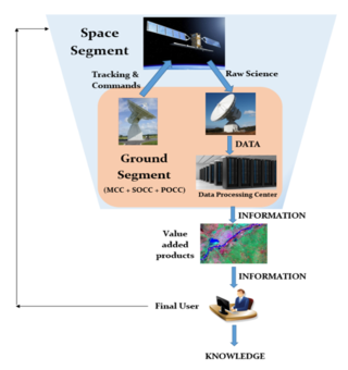
The ground segment is a critical part of the end-to-end science data return, and includes all the ground-based elements used to collect and disseminate information from the satellite to the end user (Figure 11.1). The primary elements of a ground system are summarized in Table 11-1.
Significant changes are occurring across government and commercial ground stations and services, along with evolving integration between these sectors. Since its inception in 1958, NASA has relied on internally developed systems to receive data from Earth-observing satellites and communicate with astronauts in orbit. Over time, commercial providers developed the capabilities to reliably and securely communicate with objects in low-Earth orbit (LEO), services that NASA is increasingly procuring as a near-Earth mission customer.
NASA combined the Near Earth Network (NEN) and the Space Network (SN) into the Near Space Network (NSN) in October of 2020. To support commercialization initiatives, NASA plans to increase reliance on industry-provided communications services for near-Earth missions by 2030 (1). As of 2026, commercial providers do not support missions at Sun-Earth Lagrange Points or in Deep Space; therefore, the Deep Space Network (DSN) and large NSN assets (≥18 m) continue to play a critical and needful role in returning science data from these regions for heliophysics, astrophysics and planetary science missions.
| Table 11-1: Primary Elements of a Ground System | |
|---|---|
| Element | Function |
| Ground Stations | Telemetry, tracking, and command interface with the spacecraft |
| Ground Networks | Connection between multiple ground elements |
| Control Centers | Management of the spacecraft operations |
| Remote Terminals | User interface to retrieve transmitted information for additional processing |
The NSN provides Direct-to-Earth (DTE) services via a global system of commercial and NASA- owned ground stations that provide line of sight communications and tracking services to missions ranging from low-Earth orbit and extending to Sun-Earth Lagrange Points 1 & 2. These services are augmented by Space Relay services via relay satellites in geosynchronous orbit.
Ground segment design depends on several factors including, but not limited to:
- Data volume to satisfy mission requirements
- Location of ground assets relative to mission orbit parameters
- Budget limitations
- Distribution of the team
- Controlling organization (federal vs. non-federal users)
- Regulatory requirements
- Latency requirements
The ground system is responsible for collecting and distributing the mission’s most valuable asset: data. Selecting an appropriate ground system is critical to mission success.
All small satellites rely on some form of a ground segment to communicate with the spacecraft, ranging from hand-held radios using amateur frequencies to large dish antennas operating on licensed federal or non-federal bands. The commercial marketplace for Telemetry, Tracking and Commanding (TT&C) services continues to expand and has matured to enable commercialization of DTE radio frequency communications. NASA is fostering a growing commercial market by leveraging industry capabilities to improve the efficiency and robustness of ground networks. In addition, NASA plans to enhance its communications capabilities to provide near-continuous communications support to Artemis lunar missions through relay and navigation services in lunar space.
11.2 Ground System Architecture
A typical small satellite mission ground system architecture includes the following elements:
- Ground Station Terminal: Transmitter and receiver or transceiver at the ground station to transmit and receive information, including related hardware such as antennas. These may be in Radio Frequency (RF) or optical wavelengths.
- Mission Operations Center (MOC):
- Commands the spacecraft
- Monitors spacecraft performance
- Requests and retrieves data as necessary
- Science Operations Center (SOC):
- Generates and disseminates science data products
- Determines science operations to be relayed to the MOC
- Ground Station Data Storage and Network:
- Provides real-time connectivity to the MOC for commands and telemetry
- Temporarily stores data for retrieval by the MOC and/or SOC
- Mission Operations Center (MOC):
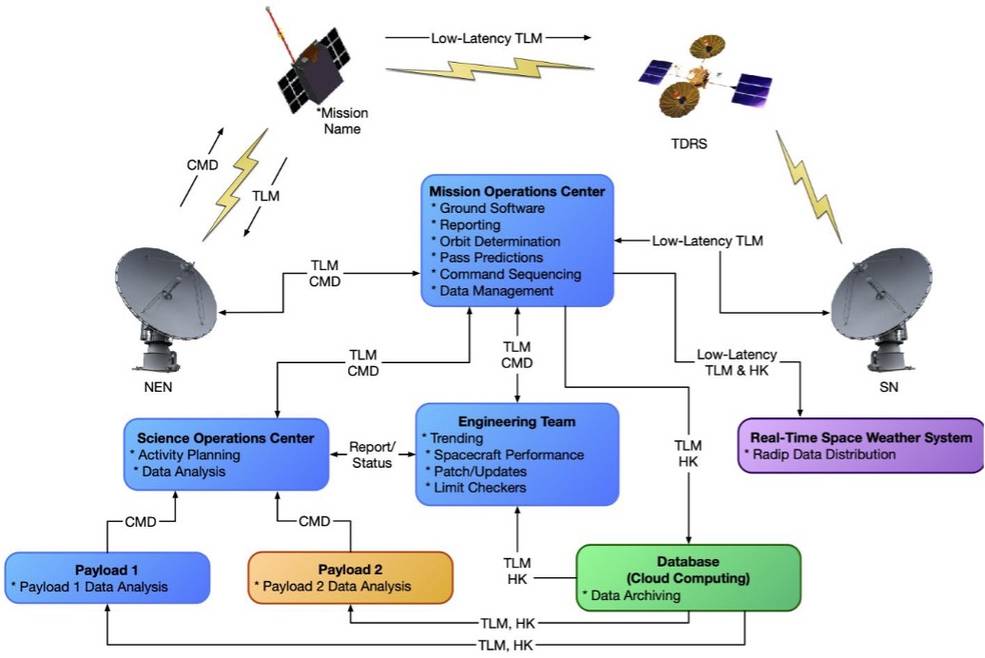
Figure 11.2 illustrates a generic small satellite ground architecture that uses NASA’s NSN for nominal ground passes and the NASA SN for low-latency communications.
In this architecture, the MOC is responsible for all communication to and from the spacecraft, while the SOC and engineering teams interface directly through the MOC to process commands. This is especially important during commissioning and troubleshooting, when engineering teams require direct access to the flight system. This architecture also provides a separate database of telemetry and housekeeping data that is generated from the MOC and accessible to stakeholders.
11.2.1 Types of Communication Infrastructures
Communications services may be either DTE or augmented by space relay. DTE ground stations provide direct point-to-point access with antennas at ground stations which are strategically located and equipped with telemetry, command, and tracking services. DTE antennas for NASA small satellites are high gain parabolic dish antennas used to support S, X, and Ka bands, while some universities still use parabolic or UHF Yagi antennas. DTE ground stations could also incorporate phased array antenna systems or equipment for optical communications. The DTE services are especially effective for missions needing frequent, short-duration contacts with high data throughput. They are also capable of handling longer latency durations due to orbital dynamics and station visibility.
Space relay services involve an intermediate satellite that communicates with a ground station on the Earth’s surface. Relay communication satellites for LEO spacecraft can be in Geosynchronous Equatorial Orbit (GEO), about 36,000 km from Earth, or in LEO. Relays are essential for providing communication and tracking when direct-to-ground communications are not feasible due to physical asset visibility constraints. It is common for a LEO spacecraft to only be in a DTE ground station’s line of sight for a portion of the orbit. The addition of space-based relay assets can provide missions with full-time coverage and continuous access to communication and tracking services. They are most useful for missions that need continuous coverage, low latencies, and coverage of launch, critical events, or emergencies.
Communication with DTE ground stations can achieve much higher data rates than what is possible for space-based relays. When considering a GEO relay satellite, it can be ten times the distance from the low-Earth orbit spacecraft than the DTE ground station. With communication propagation losses being a function of the reciprocal of the distance squared, the same communications system can achieve orders of magnitude higher data rates with the DTE ground station. Achieving comparative data rates for a relay system would require a significant increase in power. The current LEO relays have hardware limitations that permit data rates of 9.6 kbps or less, which is low relative to SmallSats being able to achieve 3 Mbps or more with DTE ground stations.
11.3 Frequency Considerations
The spacecraft transceiver and ground station need to be on a coordinated frequency to communicate. Selecting transmit and receive frequencies are a critical part of the spacecraft communications system design process. Frequencies are divided into different bands as shown in Table 11-2. See a list of supported frequencies per ground station in their specific sections.
Typical bands considered for small satellites and therefore ground stations are Ultra High Frequency (UHF), S, X, and Ka. UHF was the band of choice for early small satellites, but in recent years, there has been a shift to S, X, and Ka. A ground station needs to maintain antennas and receivers such that the ground receive matches the space segment’s transmit frequency and vice versa. Since Transmit (Tx) and Receive (Rx) have different key drivers and requirements, many ground stations are dual or tri-band.
| Table 11-2: Frequency Bands | |
|---|---|
| Band | Frequency |
| HF | 3 to 30 MHz |
| VHF | 30 to 300 MHz |
| UHF | 300 to 1000 MHz |
| L | 1 to 2 GHz |
| S | 2 to 4 GHz |
| C | 4 to 8 GHz |
| X | 8 to 12 GHz |
| Ku | 12 to 18 GHz |
| Ka | 27 to 40 GHz |
| V | 40 to 75 GHz |
| W | 75 to 110 GHz |
| mm | 110 to 300 GHz |
Ground Station Receive (Spacecraft Return, Telemetry)
Ground station receive frequencies are mostly S and X band from a LEO/ GEO orbit, and X and Ka band from deep space. Ka band has been implemented for transmit and is NASA’s desired band for future small satellite missions. This shift has been driven by higher data return demands and frequency control. The higher frequencies permit more data to be transmitted over a given period but require more stringent pointing. UHF is appealing to some universities, due to the lower cost of hardware for both the spacecraft and ground station, good link margins, and more omni-directional pattern capability with the spacecraft but yields lower data rates and has a higher probability for interference. Higher frequencies provide wider bandwidths, and the matching antennas have narrower beamwidths or are arrayed for a higher gain, thus more stringent pointing is required.
Ground Station Forward (Spacecraft Commanding)
The key driver for successfully commanding a satellite from the ground is the ability to establish and maintain a communication link. The most critical period occurs immediately after spacecraft separation from the launch vehicle, when the satellite may not yet have full control over its attitude; therefore, a wide beamwidth for the spacecraft receiving antenna(s) in the selected frequency is essential. For this reason, ground stations are designed with higher transmit power and Low-Noise Amplifiers (LNAs) to compensate for the low-gain, ideally omnidirectional single-patch receive antennas typically used in lower frequency bands.
11.3.1 Frequency Selection: Link Budget
Calculating the RF link budget is the first step when designing a telecommunications solution. It is a calculation of the end-to-end performance of the communications link with the constraint of maintaining a required link margin. Maintaining a 3 dB link margin is adequate for data return from a satellite in low-Earth orbit at a slant range of 1,500 km. Usually commanding to a Near-Earth orbit has plenty of margin because of the high power and aperture size of the ground station, and the lower required data rate on the account of the commands’ low volume. When considering deep space communication, a 3 dB link margin is desired, but for distant spacecraft, such as New Horizons at 7 billion kilometers from Earth, 1 dB or less margin may be all that is practically feasible. The budget calculation adds and subtracts all the power gains and losses that a communication signal will experience within the system. Factors such as uplink amplifier gain and noise, transmit antenna gain, slant angles and corresponding free space loss, satellite transceiver noise levels and power gains, receive antenna and amplifier gains and noise, cable losses, and atmospheric attenuation are considered. There is a duality to frequency effects: free space loss over the same range is less for lower frequencies; however, the wavelength is much smaller for higher frequencies, thus a same size ground aperture provides a much higher gain over temperature (G/T). On the spacecraft end, a multi-element high-gain Ka-band antenna array for example fits in the palm of a hand. For high volume data return, which is where communications bottlenecks occur, higher frequencies are desirable – all the way up to optical wavelengths at 1550 nm (see Section 11.10.1, Free Space Optical Communications).
11.3.2 Frequency Licensing
RF communication frequencies are intentionally protected. Within each frequency band there are government and non-government designations amongst the frequencies. Some frequencies are government use only, others are non-government only, and some are shared. Government bodies that regulate the frequency usage in the United States are the Federal Communications Commission (FCC) and the National Telecommunications and Information Administration (NTIA). Other countries may have their own national governing bodies, and all national bodies around the world must coordinate with the International Telecommunications Union (ITU), which is the governing body at the international level. The FCC is responsible for issuing communications licenses to non-government users and the NTIA handles government users. Licenses are required for both the satellite and ground station to transmit on a designated frequency or frequencies. It is becoming more common for small satellites to use multiple bands. For example, some missions have used UHF for uplink and S- band for downlink, while others have used S-band for uplink and X-band for downlink. Some of the non-government frequencies are dedicated for amateur usage.
Early university small satellites relied heavily on the use of amateur frequency bands. In recent years, there has been movement by the International Amateur Radio Union (IARU) and the FCC to significantly limit the use of amateur frequencies for small satellites. Those interested in using these frequencies are expected to first communicate their intention with the IARU and obtain a coordination letter prior to applying with the FCC. It is recommended that missions with a new communication system design apply with the FCC or NTIA once an operations concept and a spacecraft design are defined, to verify a proper communications approach and associated hardware has been selected. Missions using a legacy communications approach can typically wait until they have been given a launch manifest. The licensing process can take several months and needs to be completed prior to launch. Some of the processing time is associated with the FCC and NTIA having to also coordinate with the ITU. Both the FCC and ITU are working to implement more streamlined small satellite licensing options. Such improvements will be necessary as constellations of small satellites become more prevalent.
11.4 Ground Segment Services
Ground segment services may include the four categories below. The NSN is a full-service ground station network and offers all four major service categories. Not all commercial services offer all services.
- Mission Integration – this includes development of service agreements, interfaces, documentation, support of reviews, etc.
- Mission Planning and Scheduling – this includes performing link and loading analyses, supporting service requests, and generating and implementing operational schedules.
- User Mission Data Transfer – this primarily includes spacecraft forward command and return telemetry data.
- Position, Navigation and Timing (PNT) – this includes navigation.
Position information is critical for commanding the spacecraft. Commanding may be scripted by the mission and is actuated through ground services. Challenges are usually associated with the initial satellite-to-ground station link closure. Typically, two-line elements (TLE) or state vectors are established and shared by the launch provider after deployment. This information can be used to create an initial orbit solution for ground station antenna pointing. Low-Earth orbit missions can use North American Aerospace Defense Command (NORAD) TLE data (see https://www.space-track.org) for satellite location. However, it could take up to a week or more for NORAD to add the new object to their tracking list. This process could be delayed further if multiple spacecraft are ejected in close proximity, and it may not be clear which NORAD element set corresponds to which spacecraft. It is not uncommon to spend weeks attempting contact with different NORAD-tracked objects until the correct one is found. The position prediction accuracy based on the NORAD TLE also diverges over time and a new TLE will be needed to maintain data link. This is typically not an issue since the TLE is updated regularly, but on-board Global Positioning System (GPS) data (if equipped) can help determine the orbital parameters for the ground station to define latest orbital parameters.
Another method is to locate the satellite as it rises from the horizon. Ground station operators can point a directional antenna 5-10 degrees above the horizon to detect the satellite and synchronize with the radio. Most antenna tracking software will commence automatic tracking after the initial acquisition is successful. A half-duplex or full-duplex system could make a difference as well. Program track instead of auto-track is used for half-duplex. With a full-duplex system, the ground antenna attempts to acquire the downlink first. Predicts (NORAD or state vectors) are still used to initially acquire the spacecraft. If the predicts are off, the antenna can initiate a mechanical scan to increase the search area. Once the downlink is acquired, the ground antenna can auto-track and automatically point at the satellite for the duration of the pass. Additional passes are scheduled during spacecraft and payload commissioning. Table 11-3 describes NSN’s transport and tracking capabilities.
| Table 11-3: NSN Interfaces and Capabilities | ||
|---|---|---|
| Interface/ Capability1 | Direct to Earth | Space Relay |
| Terrestrial Link Data Transport Capabilities | ||
| Data Storage 1 | Station Storage: 5-30 days Cloud-based: Mission-driven | 7 days |
| Network Data Rate 1 | Mission-driven (up to 1.2 Gbps) | |
| SLE Protocols | F-CLTU, EF-CLTU (Forward) RAF, RCF, ROCF (Return) | |
| SLE Versions Supported 2 | CCSDS 910.4, CCSDS 911.1, CCSDS 911.2, CCSDS 911.5, CCSDS 912.1, CCSDS 912.11, CCSDS 912.3, CCSDS 913.1 | |
| Offline-Data Transfer | CFDP, SFTP | |
| Security | Trusted Networks (Access Controls, Firewalls, Authentications, etc.) | |
| Spacecraft Navigation Tracking Capabilities | ||
| Radiometric Tracking Services 1 | Tone Ranging 1-way or 2-way Doppler Antenna Angle Data | Spread Spectrum Ranging 1-way or 2-way Doppler Antenna Angle Data |
| Radiometric Measurement Accuracy 1 | Range: S-band: < 5 meters, 1σ Doppler (Range-Rate): S-band 1-way: ≤ 30 mm/s, 1σ S-band 2-way: ≤ 15 mm/s, 1σ X-band 1-way: ≤ 7 mm/s, 1σ Ka-band 1-way: ≤ 2 mm/s, 1σ Antenna Angles: S: 0.03°, X: 0.05° Ka: 0.01° (auto), 0.05° (program) | Range: ≤ 2.73 meters, 1σ Doppler (Range-Rate): 1-way ≤ 1.55 mm/s, 1σ 2-way ≤ 3.1 mm/s, 1σ Antenna Angles: ≤ 0.1° |
| Radar Tracking Service Bands | C-band (5.4-5.9 GHz) Single Object X-Band (10.499 GHz) Multi Object | N/A |
| Radar Tracking Loop Gain (dB) | C-Band: 212-245 (227 Typical) X-Band: 246 (nominal) | |
| Other 1 | Ground Antenna Slew Rate: | Time Transfer Measurement: |
| Azimuth and Elevation: ≥ 10°/sec (10°/sec2) * Train: ≥ 5°/sec (5°/sec2) * WS1 18-m system ≥ 2°/sec (1°/sec2) | User Spacecraft Clock Calibration System: ≤ ±5 μs Return Channel Time Delay: ±25% of a bit period | |
| 1 Services and performance (Data Rates, EIRP, G/T, etc.) are not uniform across assets. 2 Additional capabilities above those listed could be supported as well. 3 NASA may consider adding technologies not currently on its roadmap. 4 2nd and 3rd Generation TDRS only. | ||
Another critical time in the life of a spacecraft is commissioning; either commissioning of the spacecraft bus, or commissioning of science instruments, including in-space calibration. During commissioning phases, additional time and support personnel are typically scheduled (1).
11.4.1 Ground Networks – NASA and Partners
The ground stations, MOC, SOC, and the supporting infrastructure connecting them together, make up a ground network. Ground station antenna dish diameters, LNAs, frequency feeds, station gain over temperature (G/T) requirements are carefully selected for each network and are optimized for targeted ranges. NASA’s NSN ground network provides services to satellites up to 2 million km range from Earth; NASA owns and JPL maintains the DSN for missions beyond two million km, including planetary.
At NASA’s Goddard Space Flight Center, the Exploration and Space Communications (ESC) projects division oversees the operations, maintenance and advancement of the Space Communications and Navigation (SCaN) program office’s NSN. Operating at a high-level of reliability and proficiency, the NSN provides communications and navigation services for missions within two million kilometers of our planet, bringing down an average of almost 30 Terabytes of critical data daily. Through space relays and ground-based assets, NSN provides data delivery and satellite tracking services, empowering new discoveries about the universe and our home planet. JPL is responsible for managing and maintaining the DSN.
NASA Near Space Network
“The newly established NSN is more than just an aggregation of the NEN’s and SN’s space-based technologies, ground stations and antennas; it’s the network through which NASA and other space users will now arrange for support services for their near-Earth missions. Critically, those support services may be provisioned through government or commercial network assets in a way that is seamless to users—a cornerstone in SCaN’s effort to incorporate increasing levels of commercial service while ensuring mission needs are met.”
The NSN provides direct-to-earth telemetry, commanding, ground-based tracking, and data and communications services to a wide range of customers. The network consists of NASA, commercial, and partner S-band, X-band, and Ka-band ground stations supporting spacecraft in LEO, GEO, Highly Elliptical Orbit (HEO), Lunar orbit, and Lagrange point L1/L2 orbit up to one million miles from Earth. The NSN supports multiple robotic and launch vehicle missions with NASA-owned stations and through cooperative agreements with interagency, international, and commercial services. Table 11-4 shows the radio frequencies that the NSN supports via the NTIA.
| Table 11-4: NSN Supported Radio Frequencies and Bandwidths | ||
|---|---|---|
| Band | Function | Frequency Band (MHz) |
| S Uplink | Earth to Space | 2,025 – 2,110 |
| X Uplink | Earth to Space | 7,190 – 7,235 (Two NEN sites to 7,200) |
| S Downlink | Space to Earth | 2,200 – 2,300 |
| X Downlink | Space to Earth, Earth Exploration | 8,025 – 8,400 |
| X Downlink | Space to Earth, Space Research | 8,450 – 8,500 |
| Ka Downlink | Space to Earth | 25,500 – 27,000 |
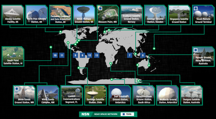
A comprehensive list of Forward and Return capabilities per frequency are in Table 11-5. Systems are compliant with most CCSDS recommendations. The NSN consists of geographically dispersed ground stations operated by NASA and its commercial partners (Figure 11.3).
Government
- NASA’s Alaska Satellite Facility, Fairbanks — Supports: S/X Band — Assets: 11.3m, 11m, 9.1m
- NASA’s Kennedy Uplink Station — Supports: S-band – Assets: 6.1m
- NASA’s Ponce de Leon Station — Supports: S-band – Assets: 6.1m
- NASA’s Wallops Ground Station (GS), Virginia — VHF, S/X Band — Assets: 11m/5m
- NASA’s White Sands GS, New Mexico — Supports: VHF, S/Ka Band — Assets: 18.3m
- NASA’s White Sand Complex, New Mexico — Supports VHF, S/Ka Band — Assets: 11m
- NASA’s McMurdo Ground Station, Antarctica — Supports: S/X Band — Assets: 10m
- Fairbanks Command and Data Acquisition Station (NOAA partnership), Gilmore Creek, Alaska
Commercial
- KSAT Singapore — Supports: S/X Band — Assets: 9.1m
- KSAT Svalbard, Norway — Supports: S/X Band — Assets: 11.3m/11.3m/13m
- KSAT TrollSat, Antarctica — Supports: S/X Band — Assets: 7.3m/7.3m
- KSAT Punta Arenas – Supports: S/X Band — Assets: 11.5m
- KSAT Inuvik — Supports: S/X Band — Assets: 13m
- SANSA Hartebeesthoek, South Africa — Supports: S/X Band — Assets: 12m/10m
- SSCKiruna, Sweden — Supports: S/X Band — Assets: 13m/13m
- SSC Santiago, Chile — Supports: S Band — Assets: 9m/12m/13m
- SSC Space US North Pole, Alaska — Supports: S/X Band — Assets: 5m/7.3m/11m/13m
- SSC Space US Dongara, Australia — Supports: S/X Band — Assets: 13m
- SSC Space US South Point, Hawaii — Supports: S/X Band — Assets: 13m/13m
| Table 11-5: NSN Direct to Earth Command and Telemetry Capabilities per Frequency | ||
|---|---|---|
| Interface/ Capability1 | Direct to Earth | Space Relay |
| Forward (Command) Communications | ||
| Frequency Bands (Near-Earth Use) | S-band: 2025-2110 MHz X-band: 7190-7235 MHz | S-band: 2025-2110 MHz Ku-band: 13.775 GHz Ka-band: 22.55-23.55 GHz 4 |
| Maximum Bandwidth | S-band: 5 MHz X-band: 10 MHz | S-band: 6 MHz Ku-band: 50 MHz Ka-band: 50 MHz 4 |
| Forward Max Data Rate 1,2 (prior to encoding) | S-band: 5 Mbps X-band: 5 Mbps | S-band MA: 300 Kbps S-band SA: 4.2 Mbps Ku-band: 50 Mbps Ka-band SA: 50 Mbps 4 |
| Antenna System EIRP (dBW) 1 | S-band: 51-81 (56 Typical) X-band: 85-86 | S-band MA: 42 4 S-band SA: 48.5 4 Ku-band SA: 48.5 4 Ka-band SA: 63 4 |
| Modulation 2,3 | PM, FM, PCM, PCM/PM, PCM/PSK/PM, BPSK, QPSK, OQPSK, UQPSK | Spread spectrum: BPSK or UQPSK Non-spread: BPSK, QPSK, OQPSK, PCM/PM, or PCM/PSK/PM |
| Encoding 2,3 | Uncoded, or LDPC ½ or 7/8 | Uncoded, Rate ½ Conv., Reed- Solomon, Concatenated (½ Conv. + RS), LDPC ½ or 7/8 |
| Polarization | Circular (LHC, RHC) | Circular (LHC, RHC) (LHC only for MA services) |
| Return (Telemetry) Communications | ||
| Frequency Bands (Near-Earth Use) | S-band: 2200-2290 MHz X-band: 8025-8400 MHz X-band (SRS): 8450-8500 MHz Ka-band: 25.5 – 27 GHz 4 | S-band: 2200-2290 MHz Ku-band: 15.0034 GHz Ka-band: 25.25 – 27.5 GHz 4 |
| Maximum Bandwidth | S-band: 5 MHz X-band: 375 MHz X-band (SRS): 10 MHz Ka-band: 1500 MHz | S-band (MAR & SAR): 6 MHz Ku/Ka-band: 225 MHz 4 Ka-band (Wide): 650 MHz 4 |
| Return Max Data Rate 1,2 (prior to encoding) | Rates will vary – examples: S-band: 2.2 Mbps (PACE) X-band: 220 Mbps (ICESat-2) X-band (SRS): 13.1 Mbps (IRIS) Ka-band: 3.5 Gbps (NISAR) | S-band MA: 1 Mbps S-band SA: 14.1 Mbps Ku/Ka-band: 600 Mbps 4 Ka-band (Wide): 1200 Mbps 4 |
| Antenna System G/T (dBW) 1 | S-band: 19.1-29.6 (21 Typical) X-band: 30.5-37.8 (32 Typical) Ka-band: 38-45 (41.3 Typical) | S-band MA: 3.2 (for LEO) S-band SA: 9.5 (for LEO) Ku-band: 24.4 (for LEO) Ka-band: 26.5 (for LEO) 4 |
| Demodulation 2,3 | PM, FM, PCM, PCM/PM, PCM/PSK/PM, BPSK, QPSK, OQPSK, AQPSK, SQPN, 8PSK | Spread spectrum: BPSK or UQPSK Non-spread: BPSK, QPSK, OQPSK, PCM/PM, or PCM/PSK/PM |
| Decoding 2,3 | Uncoded, Rate ½ Conv. and/or Reed-Solomon, LDPC ½ or 7/8, or Turbo Rate ½ | Uncoded, Rate ½ Conv., Reed- Solomon, Concatenated (½ Conv. + RS), LDPC ½ or 7/8, Rate 7/8 TPC |
| Polarization | Circular (LHC, RHC) | Circular (LHC, RHC) (LHC only for MA services) |
| 1 Services and performance (Data Rates, EIRP, G/T, etc.) are not uniform across assets. 2 Additional capabilities above those listed could be supported as well. 3 NASA may consider adding technologies not currently on its roadmap. 4 2nd and 3rd Generation TDRS only. | ||
While NASA’s NSN is often reserved for NASA-funded missions, other ground network options exist for non-government-funded satellite operators. One common option, especially amongst amateur operators, is to take advantage of the UHF and VHF amateur network around the world.
The NSN is exploring how to provide higher data rates for CubeSat missions with techniques such as Digital Video Broadcast Satellite Second Generation (DVB-S2). Higher data rates either increase science return or reduce the number of minutes per day of required ground station contacts. Higher data rates also enable mother-daughter small satellite constellations, where the mother spacecraft handles the communication with Earth for multiple daughter spacecraft. Functions such as Multiple Satellite per Aperture (MSPA) are planned to be implemented on the Lunar Exploration Ground Sites (LEGS) mission.
The NSN facilitates Commercial Services (CS) and negotiated a bulk-buy discount for all NASA missions. This allows for contacts on the NSN Contractor/University Operated and CS apertures to be at no-cost for NASA missions. The NSN does schedule CS in accordance with NASA mission-defined priority. The Networks Integration Management Office (NIMO) at NASA GSFC is the liaison for customers that wish to use NSN services. NIMO has a variety of services and capabilities available and can coordinate support from providers throughout NASA, other US agencies, US commercial entities, and foreign governments. Some of the services that NIMO can provide include:
- Requirements Development
- Communications Design Support & Guidance
- Optical Communications Analysis
- Network Feasibility Analysis
- Spectrum Management
- RF Compatibility Testing
- Launch Support
Network Feasibility Analysis includes determining NSN station loading as a function of the mission’s priority and determining the availability of planned stations for the contacts requested. Prior to the mission deployment, the NSN commits to providing the requested stations and contact time as outlined in the network feasibility analysis.
For new customer mission service requests please fill out the NSN Service Inquiry Form at: http://go.nasa.gov/NSNServiceInquiry.
If interested in more information on using the Near Space Network (NSN), please also refer to https://esc.gsfc.nasa.gov/projects/NSN.
NASA Deep Space Network
The DSN is optimized to conduct telecommunication and tracking operations with space missions in GEO. This includes missions at lunar distances, the Sun-Earth LaGrange points, and in highly elliptical Earth orbits, as well as missions to other planets and beyond. The DSN has supported, or is currently supporting, missions to the Sun as well as every planet in the Solar System (including dwarf planet Pluto). Two missions (Voyager I and Voyager II) have reached interstellar space and still communicate with the DSN. The DSN offers services to a wide variety of mission customers, as shown in Table 11-6.
| Table 11-6: DSN Customers, Mission Characteristics, Frequencies, and Services | |
|---|---|
| Customers | Mission Phases |
| • NASA • Other Government Agencies • International Partners | • Launch and Early Orbit Phase (LEOP) • Cruise • Orbital • In-Situ |
| Mission Trajectories | Frequency Bands – Includes Near-Earth and Deep Space Bands, Uplink and Downlink, Command, Telemetry, and Tracking Services |
| • Geostationary or GEO • HEO • Lunar • LaGrange • Heliocentric • Planetary | • S-Band (2 GHz) • X-Band (7, 8 GHz) • Ka-Band (26, 32 GHz) |
DSN services include:
- Command Services
- Telemetry Services
- Tracking Services
- Calibration and Modeling Services
- Standard Interfaces
- Radio Science, Radio Astronomy and Very Long Baseline Interferometry Services
- Radar Science Services
- Service Management
Custom and tailored DSN services can also be arranged for missions and customers. DSN- provided data services are accessed via well-defined, standard data and control interfaces:
- The CCSDS
- The Space Frequency Coordination Group (SFCG)
- The ITU
- The International Organization for Standardization (ISO)
- De facto standards widely applied within industry
- Common interfaces specified by the DSN
The use of data service interface standards enable interoperability with similar services from other providers.
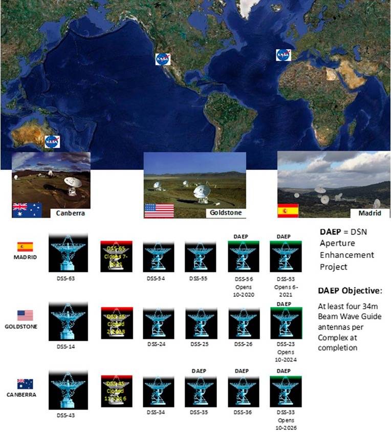
Figure 11.4 shows the DSN antennas and their locations. Each DSN ground station in California (United States), Madrid (Spain), and Canberra (Australia) currently as of 2021 was operating four 34 m Beam Wave Guide antennas and one 70 m antenna. By the late 2020s, this is planned to increase to include one 70 m plus four 34 m antennas at each DSN site.
The DSN supports RF testing using the following facilities:
- Development and Test Facility (DTF-21), located near NASA Jet Propulsion Laboratory (JPL)
- Compatibility Test Trailer (CTT-22), able to come to the spacecraft site
For more information on DSN, please see:
- https://www.nasa.gov/directorates/space-operations/space-communications-and-navigation-scan-program/scan-services-and-scheduling
- https://deepspace.jpl.nasa.gov/about/commitments-office
- https://deepspace.jpl.nasa.gov
Swedish Space Corporation
Swedish Space Corporation (SSC) is a global provider of ground station services, including support to launch and early operations, on-orbit TT&C and data downlink, and even lunar services (see https://sscspace.com/). The SSC Infinity Network is specifically designed for constellations of small satellites in low-Earth orbits. The global network provides TT&C and data download and delivery services to SmallSat operators, and customer interfaces consist of web-based portals for pass scheduling on 5-meter and smaller antennas. SSC Infinity also uses standard configurations and standardized ground system hardware, limiting the number of mission configurations to help keep costs lower for satellite operators.
Using ground services will generally require some degree of pre-coordination (or “onboarding”) between the operator and provider, which is usually done before launch. This will vary between providers but may include contracting mechanisms; frequency licensing and coordination between the operator and the provider; compatibility testing; and the sharing of mission and vehicle-specific information to ensure the ground stations are properly configured for the operator to use. Once the onboarding process is complete, satellite operators can schedule passes between their satellite(s) and desired ground station(s) in advance (the time window varies for each provider). The schedules for each ground station are deconflicted based on scheduling priority, and all frequency and modulation adjustments for the satellite are completed in advance of the pass by the service provider.
KSATLITE
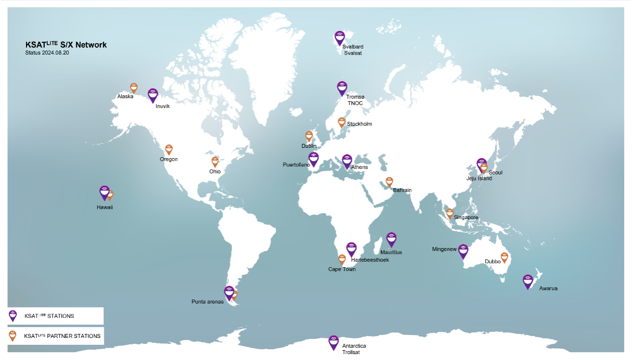
The baseline of Kongsberg Satellite Services AS (KSAT)’s 3.7-meter KSATLITE antennas provide X-band and S-band for downlink and S-band for uplink. KSAT operates over 100 KSATLITE antennas at 15+ ground station sites across the globe, supporting over 1.5 million passes in 2023 alone. In addition, KSATLITE offers a global Ka-band network capable of supporting missions with higher data rates. KSATLITE is an extension of the existing KSAT ground station antenna network with lower costs, increased flexibility, and improved availability and pass selection. The KSAT network has uniquely located polar stations in the Arctic and Antarctic regions, providing 100% availability on passes for spacecraft in polar orbit. The network also includes mid-latitude ground stations, providing access for diverse orbits and mission profiles.
Additionally, KSAT has a network of large aperture antennas that are purpose built for supporting missions in cis-lunar space and beyond. In 2023 KSAT invested in a network of three 20m LEGS-class antennas that will be placed around the globe to provide full coverage of the Moon, which will be fully operational by Q1 of 2027. See Figure 11.5 for 2024 KSATLITE ground network map.
11.4.2 Ground Segment as a Service (GSaaS)
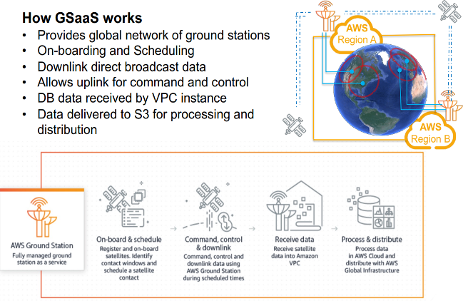
Ground Station as a Service (GSaaS) is a managed service which enables customers to communicate, downlink, and process data from their satellites/spacecrafts on as a pay-as-you go basis without needing them to build their own satellite ground stations. These services are usually scalable and use edge cloud services as an intermediate for customers data (3)(4).
AWS Ground Station
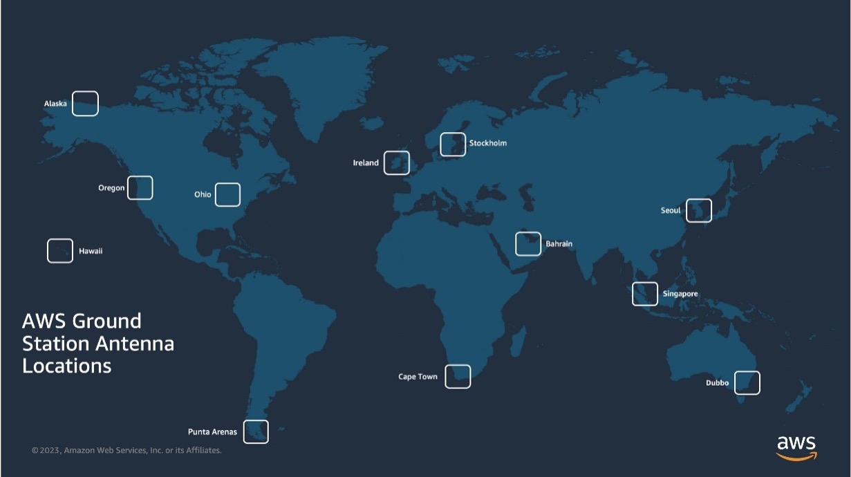
AWS Ground Station is a managed service (Figure 11.6.) that lets customers build ground segment architectures in the cloud to control their satellites, process satellite data, and scale satellite operations without having to worry about building or managing their own antenna infrastructure. Customers can stream satellite data from any of the AWS antennas to the Amazon Elastic Compute Cloud (EC2) for real-time processing or to directly store data in the Amazon Simple Storage Service (S3). Additionally, customers can easily integrate their space workloads with other AWS services in near real-time using Amazon’s low-latency, high-bandwidth global network. For example, customers who downlink terabytes of data daily can easily access AWS services such as Amazon SageMaker to quickly derive useful information. Other AWS services include Amazon VPC, Amazon Rekognition, and Amazon Kinesis Data Streams. These services allow operators to reduce data processing and analysis times for use cases like weather prediction or natural disaster imagery from hours to minutes or seconds. This also enables operators to quickly create business rules and workflows to organize, structure, and route the satellite data before it can be analyzed and incorporated into key applications such as imaging analysis and weather forecasting. A map of the AWS Ground Station antenna regions is shown in Figure 11.7.
AWS Ground Station offers 5.4-meter apertures at each of the antenna regions. AWS Ground Station provides satellite antennas direct access to AWS services for faster, simpler, and more cost-effective storage and processing of downloaded data. Frequencies and link parameters are as follows:
- S-band uplink: 2025-2120 MHz
- S-band downlink: 2200-2300 MHz with G/T of 16 dB/K
- X-band downlink: 7750-8400 MHz with G/T of 30.5 dB/K
AWS Ground Station antennas are interconnected via Amazon’s low-latency, highly reliable, scalable, and secure global network backbone. As of September 2024, the AWS Cloud spans 108 Availability Zones within 34 geographic regions around the world, with announced plans for 18 more Availability Zones and 6 more AWS Regions in Mexico, New Zealand, the Kingdom of Saudi Arabia, Thailand, Taiwan, and the AWS European Sovereign Cloud.
Customers have access to multiple billing structures including pay-as-you-go (PAYG) option, where customers pay only for what they use on a per minute basis; Dedicated Mission Support (DMS) option, where customers would receive schedule prioritization on one antenna for their constellation; or Dedicated Antenna Solution (DAS) option, where AWS collaborates with customers to design a custom solution tailored to specific mission requirements, including support for specific spectrum bands, antenna apertures, and/or locations. The PAYG, DMS, and DAS solutions can also be combined for additional capacity needs.
Scheduling: AWS Ground Station provides an easy-to-use graphical console that allows operators to reserve contacts and antenna time for their satellite communications. They can review, cancel, and reschedule contact reservations up to 15 minutes prior to scheduled antenna times. Access can be scheduled to AWS Ground Station antennas on a per-minute basis, so operators only pay for the scheduled time. They can access any antenna in the ground station network, and there are no long-term commitments. https://aws.amazon.com/ground-station.
Leaf Space
Leaf Space is a ground-segment-as-a-service provider, operating a globally distributed ground station network to support satellites of any size in LEO, MEO and GEO environments. Leaf Space’s “Leaf Line” network (see Figure 11.8) enables TT&C and payload data transmissions to and from the satellite operators’ mission control software and delivery endpoint of choice. Leaf does so via a simple API interface, a proprietary autonomous scheduling software, and global network coverage, supporting satellites in every LEO orbit – mid, high, equatorial-inclination. Leaf Line antennas are fully owned or fully managed, ensuring maximum availability, flexibility, and independence of operations. Leaf Line is powered and orchestrated by a secure cloud architecture designed to support multiple satellite missions and operators at the same time. The network’s secure architecture allows seamless use of any antenna without requiring any further resource overheads or worrying about varying performance over different ground stations. Leaf Space works closely with its customers to execute both routine operations and complex tasks such as LEOP or custom CONOPS.
Leaf Line consists of 3.7m and 3.9m diameter antennas and supports operations in S-band uplink (2025-2110 MHz, EIRP: 50 dBW), S-band downlink (2200-2290 MHz, G/T: 12.8 dB/K), X-band downlink (8025-8500 MHz, G/T: 25.4 dB/K), and Ka-band downlink (25.5-27 GHz, G/T: 30.0 dB/K). Leaf Space is constantly improving its network architecture in terms of sites, capacity, antenna performances and pass scheduling flexibility, in order to cater to a wide variety of customers. With an eye towards the future of the sector, Leaf Space is working to integrate larger-aperture antennas for GEO missions, optical ground systems as well as cislunar-oriented solutions to its existing network.
In addition to providing access to the Leaf Line network, Leaf Space procures, deploys, and operates dedicated and/or custom ground stations for its customers (a service offering called “Leaf Key”), enabling operators with non-standard frequencies, access, or data requirements to leverage Leaf Space’s cloud architecture and ground segment experience without compromising on antenna time. For more information, please contact sales@leaf.space or visit https://leaf.space.
Laser Light Communications
Laser Light Communications operates a Global Network platform, delivering a first-of-a-kind 21st century data service that will transform the way high volume communications traffic is carried. Using a hybrid infrastructure spanning terrestrial, subsea, and space domains, an end-to-end software defined architecture provides up to 400 Gbps of all-optical connectivity and provisioning within minutes (see https://www.laserlightcomms.com/).
Network On Demand
- Pay-as-you-go: only pay for the duration you use the service with no upfront or fixed costs.
- Cost Effective: automation and end-to-end control yields significant operating cost savings.
- Secure: highly targeted, dynamic, laser links are extremely difficult to intercept and can be encrypted.
- High Capacity/ Performance: data delivery at up to 400 Gbps in the most direct route from origination to destination, automatically bypassing points of congestion.
Data Transport as a Service
- Pay-as-you-go: only pay for volume you use when you use it with no upfront or fixed costs.
- Cost Effective: automation and end-to-end control yield significant operating costs savings.
- Secure: highly targeted, dynamic, laser links are extremely difficult to intercept and can be encrypted.
- High Capacity/Performance: data delivery at optical speeds — up to 400 Gbps directly from the point of origination to the point of destination, automatically bypassing points of congestion along the way.
Atlas Global Network
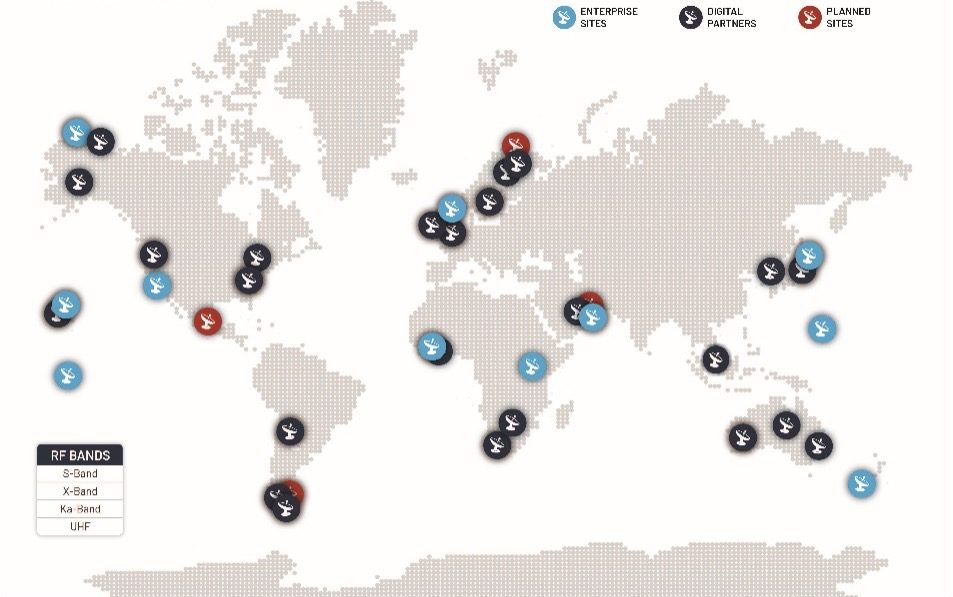
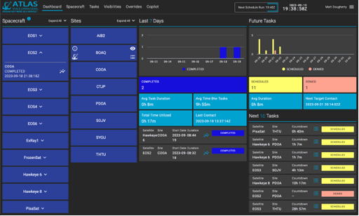
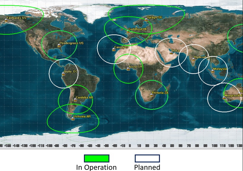
ATLAS Space Operations, Inc. provides satellite RF communication services to the government and commercial sectors through geographical dispersion and cloud services, offering GSaaS on a global network of 34 ground stations and 51 antennas, see Figure 11.9. (https://atlasspace.com/).
All ATLAS ground stations are built upon the Freedom™ Software Platform (Figure 11.10 below) within a cloud-based distributed operations center which facilitates dynamic demand and scalable growth. Through geographical dispersion of its ground stations and cloud services, ATLAS provides a resilient capability that delivers dependable low latency data. ATLAS bases its mission success model on its global network of operational and traditional RF parabolic ground stations that are integrated with network management and scheduling software. These platforms work together as a mission architecture to meet customer requirements for routine satellite-to-ground communications.
ATLAS’ Global Antenna Network is fully integrated with the Freedom Software, providing users with a robust, low latency, and secure communications solution, including: automated network operations, set-and-forget scheduling, mixed modem capability, real-time metrics, and single secure VPN access. Once integrated into the ATLAS Network, a single secure VPN enables access and load balancing of network resources. Freedom Core Services advance operations beyond legacy constructs and enable users the freedom and flexibility to reliably schedule satellite passes with minimal human interaction via machine-to-machine capabilities. Entire data processing and forwarding workflows can be automated within the cloud to ensure spacecraft data is ready for use as soon as it arrives at the Mission Operations Center.
ATLAS supports deploying clusters and serverless instances onto AWS. ATLAS hardware parameters are highlighted below (ATLAS Enterprise Sites and Digital Partner Sites). In addition to S-band and X-band capabilities, ATLAS can provide VHF, UHF services in Japan and Guam. The existing and planned ATLAS antenna systems support RF connectivity for LEO, MEO, GEO, and L1 orbits. ATLAS is actively pursuing technology development for deep space capabilities. ATLAS’ global federated network is also displayed below. A summary of government and commercial ground stations and antennas in Table 11-7 and shown in Figure 11.10 is ATLAS’ Global Federated Network of ground stations.
Freedom Space Technologies, headquartered in Colorado Springs, CO, was established as a non-traditional small business and wholly-owned subsidiary of ATLAS Space Operations. Their purpose is to address and support the Department of Defense (DoD) and Intelligence Community (IC) mission requirements.
| Table 11-7: ATLAS Federated Antenna Network | ||||||||
|---|---|---|---|---|---|---|---|---|
| Location | Lat | Long | Antenna Size (m) | Rx Freq (MHz) | G/T Long (dB/K) | Tx Freq (MHz) | EIRP (dBW) | Polariza-tion |
| Utqiagvik (Barrow), AK, USA | 71.27 | -156.81 | 3.7 | S: 2200-2300 X: 7900-8400 | 12.8 25.4 | S: 2025-2120 | 60.0 | R/LHCP |
| Dundee, Scotland | 56.40 | -3.18 | 3.7 | S: 2200-2400 R/LHCP X: 7800-8400 | 13.6 26.5 | S: 2025-2120 | 48.0 | R/LHCP |
| Chitose, Japan | 42.77 | 141.62 | 3.4 | S: 2200-2300 X: 7900-8500 | 11.5 26.4 | S: 2025-2120 | 52.0 | R/LHCP |
| Mojave, CA, USA | 35.05 | -118.15 | 3.0 | S: 2200-2300 X: 7900-8500 | 11.3 25.9 | S: 2025-2110 | 54.4 | R/LHCP |
| Dubai, United Arab Emirates | 24.94 | 55.35 | 3.7 | S: 2200-2300 X: 7900-8400 | 12.8 25.4 | S: 2025-2120 | 50.0 | R/LHCP |
| Paumalu, Hawaii, USA | 21.67 | -158.03 | 7.3 | S: 2200-2300 X: 7900-8500 | 20.7 31.0 | S: 2025-2120 | 65.0 | R/LHCP |
| Harmon, Guam | 13.51 | 144.82 | 3.7 | S: 2200-2300 X: 7900-8400 | 13.6 25.1 | S: 2025-2110 | 52.4 | R/LHCP |
| Sunyani, Ghana | 7.34 | -2.34 | 3.0 | S: 2200-2300 | 12.4 | S: 2025-2110 | 50.1 | RHCP |
| Mwulire, Rwanda | -1.96 | 30.39 | 9.3 | S: 2200-2300 X: 7900-8500 | 21.5 36.0 | S: 2025-2120 | 60.0 | R/LHCP |
| Tahiti, French Polynesia | -17.63 | -149.60 | 3.7 | S: 2200-2300 X: 7900-8400 | 13.9 27.4 | S: 2025-2110 | 47.5 | R/LHCP |
| Awarua, New Zealand | -46.52 | 168.38 | 3.7 | S: 2200-2300 X: 8025-8500 | 13.7 27.0 | S: 2025-2120 | 49.0 | R/LHCP |
| Sodankylä, Finland* | 67.36 | 26.63 | 7.3 | S: 2200-2300 X: 7900-8500 | 19.8 32.1 | S: 2025- 2110 | 54.8 | R/LHCP |
| Öjebyn, Sweden | 65.33 | 21.42 | 7.3 | S: 2200-2290 X: 8025-8400 Ka: 25500-27000 | 18.0 32.0 35.7 | S: 2025- 2110 | 55.2 | R/LHCP |
| North Pole, Alaska, USA | 64.79 | -147.53 | 7.3 | S: 2200-2300 X: 8000-8500 Ka: 25500-27000 | 19.0 32.0 35.7 | S: 2025- 2120 | 53.0 | R/LHCP |
| Stockholm, Sweden* | – | – | 5.4 | S: 2200-2300 X: 7750-8400 | 16.0 30.5 | S: 2025- 2120 | 50.0 | R/LHCP |
| Dublin, Ireland* | – | – | 5.4 | S: 2200-2300 X: 7750-8400 | 16.0 30.5 | S: 2025- 2120 | 50.0 | R/LHCP |
| Guildford, United Kingdom | 51.24 | -0.61 | 5.4 | S: 2200-2290 X: 8025-8400 | 17.0 30.0 | S: 2025- 2110 | 53.2 | R/LHCP |
| Portland, Oregon, USA* | – | – | 5.4 | S: 2200-2300 X: 7750-8400 | 16.0 30.5 | S: 2025- 2120 | 50.0 | R/LHCP |
| Obihiro, Japan | 42.59 | 143.45 | 7.3 | S: 2200-2290 X: 8025-8400 Ka: 25500-27000 | 17.9 31.5 35.0 | S: 2025- 2110 | 55.2 | R/LHCP |
| Columbus, Ohio, USA* | – | – | 5.4 | S: 2200-2300 X: 7750-8400 | 16.0 30.5 | S: 2025- 2120 | 50.0 | R/LHCP |
| Seoul, South Korea* | – | – | 5.4 | S: 2200-2300 X: 7750-8400 | 16.0 30.5 | S: 2025- 2120 | 50.0 | R/LHCP |
| Pendergrass, Georgia, USA | 34.17 | -83.67 | 5.4 | S: 2200-2290 X: 8025-8400 | 17.0 30.0 | S: 2025- 2110 | 53.2 | R/LHCP |
| Deadhorse, Alaska, USA* | – | – | 5.4 | S: 2200-2300 X: 7750-8400 | 16.0 30.5 | S: 2025- 2120 | 50.0 | R/LHCP |
| Zallaq, Bahrain* | – | – | 5.4 | S: 2200-2300 X: 7750-8400 | 16.0 30.5 | S: 2025- 2120 | 50.0 | R/LHCP |
| Kapolei, Hawaii, USA* | – | – | 5.4 | S: 2200-2300 X: 7750-8400 | 16.0 30.5 | S: 2025- 2120 | 50.0 | R/LHCP |
| Accra, Ghana | 5.74 | -0.30 | 7.3 | S: 2200-2290 X: 8025-8400 Ka: 25500-27000 | 18.0 32.0 35.7 | S: 2025- 2110 | 65.0 | R/LHCP |
| Singapore* | – | – | 5.4 | S: 2200-2300 X: 7750-8400 | 16.0 30.5 | S: 2025- 2120 | 50.0 | R/LHCP |
| Alice Springs, Australia* | -23.75 | 133.88 | 7.3 | S: 2200-2290 X: 8025-8400 Ka: 25500-27000 | 18.0 32.0 35.7 | S: 2025- 2110 | 65.0 | R/LHCP |
| Pretoria, South Africa | -25.88 | 27.70 | 7.3 | S: 2200-2290 X: 8025-8400 Ka: 25500-27000 | 18.0 32.0 35.7 | S: 2025- 2110 | 55.2 | R/LHCP |
| Mingenew, Australia* | -29.01 | 115.34 | 5.0 | S: 2200-2300 X: 8025-8500 | 14.0 29.5 | S: 2025-2120 | 55.0 | R/LHCP |
| Cordoba, Argentina | -31.52 | -64.46 | 5.4 | S: 2200-2290 X: 8025-8400 | 17.0 30.0 | S: 2025- 2110 | 53.2 | R/LHCP |
| Cape Town, South Africa* | – | – | 5.4 | S: 2200-2300 X: 7750-8400 | 16.0 30.5 | S: 2025- 2120 | 50.0 | R/LHCP |
| Dubbo, Australia* | – | – | 5.4 | S: 2200-2300 X: 7750-8400 | 16.0 30.5 | S: 2025- 2120 | 50.0 | R/LHCP |
| Punta Arenas, Chile* | – | – | 5.4 | S: 2200-2300 X: 7750-8400 | 16.0 30.5 | S: 2025- 2120 | 50.0 | R/LHCP |
| Ushuaia, Argentina | -54.51 | -67.11 | 7.3 | S: 2200-2290 X: 8025-8400 Ka: 25500-27000 | 17.9 32.0 33.0 | S: 2025- 2110 | 56.0 | R/LHCP |
Viasat
Viasat has delivered hundreds of ground antennas to NASA, other civilian space agencies, governments, and satellite industry partners throughout the world since the 1960s and has recently become a ground service provider. This move leverages decades of hardware engineering, with the global Real-Time Earth (RTE) network of ground terminals, complemented by a satellite relay network philosophy in GEO for low latency (near-real time) applications. A map of ground assets is shown in Figure 11.10. Viasat operates 7.3 m and 5.4 m antennas in 3 frequency bands (Table 11-8) and plans to include 13m class antennas in the near future. The RTE ground segment service enables communications for next-generation and legacy LEO satellites using S, X, and Ka-bands. RTE offers downlinks from low megabits per second to multiple gigabits per second powered by cutting edge software-defined radios at each site. The service includes high-speed connectivity for backhaul, real-time data streaming, and real-time monitoring of overhead passes. Following a contract award on the NASA NSN Service contract and successful completion of the capability validation task order, Viasat RTE is now available to current and future NASA missions.
Viasat’s HaloNet provides a turnkey launch and orbital communications solution with multi-band GEO-relay and Direct-to-Earth satellite links. It supports mission requirements including launch telemetry, TT&C, low- and high-data rate transmission, contingency operations, and science alerts. The system manages hardware, system integration, end-to-end transport, and service support, and communications are enabled through Viasat’s space relay constellation and small terminals that connect directly to Viasat’s GEO spacecraft. Data are delivered to the Mission Operations Center (MOC) via Viasat’s secure, redundant global IP network. HaloNet ensures resilience through multiple transport paths and multi-waveform terminals. Services include continuous or on-demand L-band TT&C for Low Earth Orbit (LEO) spacecraft, high-throughput Ka-band links, and DTE solutions. Viasat’s spectrum resources and orbital positions provide reliable and secure communications for launch and spacecraft operations. Visit https://www.viasat.com/ for more information.
| Table 11-8: Viasat Ground Stations | ||||||
|---|---|---|---|---|---|---|
| Location | Antenna | L-band Uplink | S-band Uplink | S-band Downlink | X-band Downlink | Ka-band Downlink |
| Pendergrass, GA, USA (PGG) | 5.4 m X-Y Full motion 5 o/sec max speed | N/A | 2025-2110 MHz EIRP: 53.2 dBW Selectable RHCP or LHCP | 2200-2290 MHz G/T: 17 dB/K Simultaneous RHCP and LHCP | 8025-8400 MHz G/T: 30 dB/K Simultaneous RHCP and LHCP | N/A |
| Guildford, UK (GDD) | 5.4 m X-Y Full motion 5 o/sec max speed | N/A | 2025-2110 MHz EIRP: 53.2 dBW Selectable RHCP or LHCP | 2200-2290 MHz G/T: 17 dB/K Simultaneous RHCP and LHCP | 8025-8400 MHz G/T: 30 dB/K Simultaneous RHCP and LHCP | N/A |
| Alice Springs, AU (ASP01, ASP02) | 7.3 m X-Y Full motion 6 o/sec max speed quantity 2 | 1755-1850 MHz EIRP: 63.4 dBW | 2025-2110 MHz EIRP: 65.0 dBW Selectable RHCP or LHCP | 2200-2290 MHz G/T: 18 dB/K Simultaneous RHCP and LHCP | 8025-8400 MHz G/T: 32 dB/K Simultaneous RHCP and LHCP | 25500-27000 MHz G/T: 34.5 dB/K Simultaneous RHPC and LHCP |
| Accra, Ghana (ACC) | 7.3 m X-Y Full motion 6 o/sec max speed | 1755-1850 MHz EIRP: 63.4 dBW | 2025-2110 MHz EIRP: 65.0 dBW Selectable RHCP or LHCP | 2200-2290 MHz G/T: 18 dB/K Simultaneous RHCP and LHCP | 8025-8400 MHz G/T: 32 dB/K Simultaneous RHCP and LHCP | 25500-27000 MHz G/T: 34.5 dB/K Simultaneous RHCP and LHCP |
| Cordoba, AR (COR) | 5.4 m X-Y Full motion 5 o/sec max speed | N/A | 2025-2110 MHz EIRP: 53.2 dBW Selectable RHCP or LHCP | 2200-2290 MHz G/T: 17 dB/K Simultaneous RHCP and LHCP | 8025-8400 MHz G/T: 30 dB/K Simultaneous RHCP and LHCP | N/A |
| Öjebyn, Sweden (OJY) | 7.3 m X-Y Full motion 6 o/sec max speed | N/A | 2025-2110 MHz EIRP: 55.2 dBW Selectable RHCP or LHCP | 2200-2290 MHz G/T: 18 dB/K Simultaneous RHCP and LHCP | 8025-8400 MHz G/T: 32 dB/K Simultaneous RHCP and LHCP | 25500-27000 MHz G/T: 34.5 dB/K Simultaneous RHCP and LHCP |
| Pretoria, South Africa (PRY) | 7.3 m X-Y Full motion 6 o/sec max speed | N/A | 2025-2110 MHz EIRP: 55.2 dBW Selectable RHCP or LHCP | 2200-2290 MHz G/T: 18 dB/K Simultaneous RHCP and LHCP | 8025-8400 MHz G/T: 32 dB/K Simultaneous RHCP and LHCP | 25500-27000 MHz G/T: 34.5 dB/K Simultaneous RHCP and LHCP |
| Obihiro, Japan (OBO) | 7.3 m X-Y Full motion 6 o/sec max speed | N/A | 2025-2110 MHz EIRP: 55.2 dBW Selectable RHCP or LHCP | 2200-2290 MHz G/T: 18 dB/K Simultaneous RHCP and LHCP | 8025-8400 MHz G/T: 32 dB/K Simultaneous RHCP and LHCP | 25500-27000 MHz G/T: 34.5 dB/K Simultaneous RHCP and LHCP |
| North Pole Alaska USA 7.3 m (NTP01) | 7.3 m El-Az-Train El & Az: 15 o/s max speed Train 6 o/s max | N/A | 2025 – 2120 MHz EIRP: 53 dBW Selectable RHCP or LHCP | 2200–2300 MHz G/T: 19 dB/K Simultaneous RHCP and LHCP | 8000–8500 MHz G/T: 32 dB/K Simultaneous RHCP or LHCP | N/A |
| North Pole Alaska USA (9.1 m (NTP02) | 9.1 m El-Az-Train | N/A | 2042–2052 MHz EIRP 38 dBW Selectable RHCP or LHCP | N/A | 8000–8500 MHz G/T: 34 dB/K RHCP | N/A |
| Tierra del Fuego, Argentina (USH) | 7.3 m El-Az-Train El & Az: 15 o/s max speed Train 6 o/s max | N/A | 2025-2110 MHz EIRP: 55.2 dBW Selectable RHCP or LHCP | 2200-2290 MHz G/T: 17.9 dB/K Simultaneous RHCP and LHCP | 8025-8400 MHz G/T: 32 dB/K Simultaneous RHCP and LHCP | 25500-27000 MHz G/T: 34.7 dB/K Simultaneous RHCP and LHCP (Upgrade required) |
| Dubai, UAE | 9.1 m El-Az-Train | 2025-2110 MHz EIRP 38 dBW Selectable RHCP or LHCP | 2200-2290 MHz G/T: 20 dB/K Simultaneous RHCP and LHCP | 8025-8400 MHz G/T: 34 dB/K Simultaneous RHCP and LHCP | N/A | |
| *Denotes antenna redundancy | ||||||
11.4.3 Space Relay Network – NASA
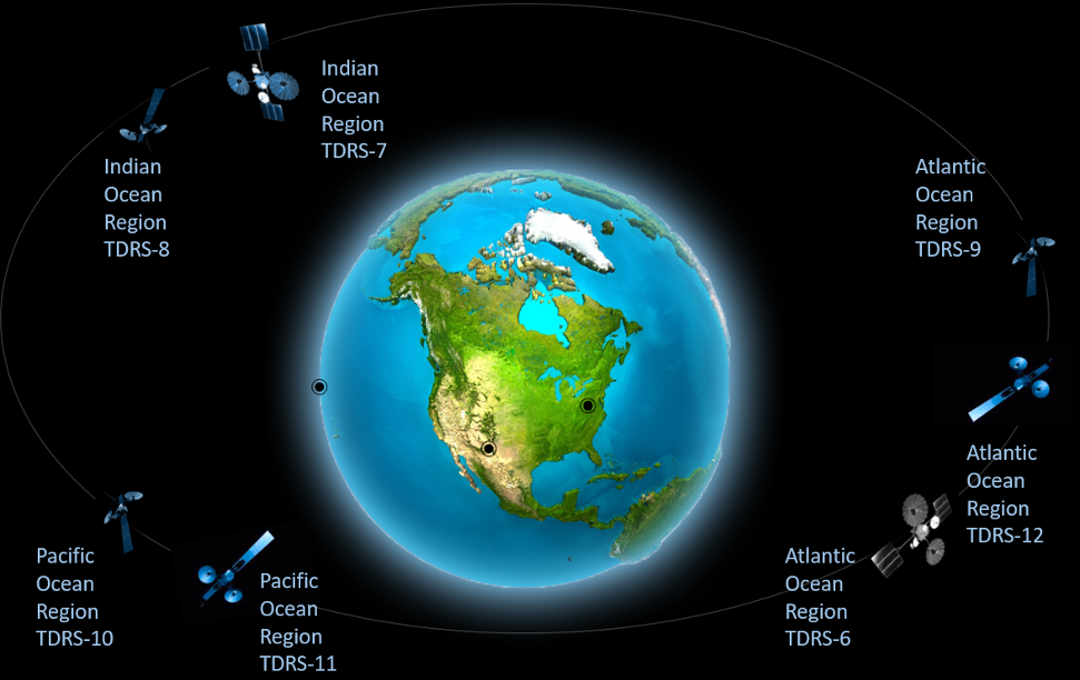
Unlike a traditional ground network that communicate directly from a “client” satellite to a ground station on the ground, space relay networks use intermediary communication satellites to relay data from the “client” satellite down to a ground station. Although some no longer consider it state-of-the-art, NASA’s Tracking and Data Relay Satellite System (TDRSS), shown in Figure 11.12, remains one of the most well-known space relay networks. TDRSS relays data from the International Space Station (ISS) and the Hubble Space Telescope to NASA ground stations around the world.
Space relay networks can be beneficial for small satellites in low-Earth orbit because those SmallSats are only in view of a ground station for a portion of their orbit. However, depending on the orbit of the relay satellites, a low-Earth orbit SmallSat may remain in view of a relay satellite for most of its orbit. This makes relay networks particularly beneficial for a SmallSat, especially immediately after deployment when ground stations are still attempting to acquire the satellite. The relay network can transmit satellite telemetry, tracking, and control data to the ground, enabling faster satellite identification. This capability is particularly valuable when satellites are deployed with multiple spacecraft during a rideshare mission. This data can also contain satellite health information to provide mission teams with insight while awaiting ground station acquisition or troubleshooting information prior to commissioning. Another benefit is the ability to obtain real-time event notifications without prior scheduling. Scientists are interested in using this technology to alert the scientific community when certain phenomenon are observed. Space relay networks often require specialized hardware or software that must be integrated into a satellite prior to launch. In general, a satellite operator will purchase a modem compatible with the relay network and integrate it into their spacecraft to access the network. It is common for network providers to license proprietary chipsets to developers who build modem hardware and act as service brokers. Because of this added hardware requirement, the decision to leverage a space relay network must be made prior to launch.
11.4.4 Low Latency, Low rate (Short burst) Space Relay Providers
Space relay solutions are less common than traditional direct-to-Earth systems, but several options exist for small satellites (see Table 11-9). To access a space relay network, a satellite operator purchases a modem from the relay provider and integrates it onto their satellite to access relay services. In general, space relays are best suited for obtaining satellite TT&C data (health and safety of the vehicle) rather than supporting large data downlinks.
| Table 11-9: Service Providers for Space Relay Networks | |||
|---|---|---|---|
| Product | Manufacturer | TRL | Specifications |
| Iridium Global Network | Iridium | 9 | LEO relay requiring 9600 series transceivers onboard the satellite |
| Fast Pixel Network | Analytical Space | 6 | Establish a data transport network in LEO |
The Iridium network is one example that satellite operators can use for delivering low-latency messages. Iridium uses a combination of Frequency Division Multiple Access (FDMA) and Time Division Multiple Access (TDMA) for its communication waveforms. L-band (1616–1626.5 MHz) is used for uplink and downlink between the user spacecraft and the Iridium constellation. Inter-satellite communication links between Iridium satellites are accomplished through Ka-band (23.18–23.28 GHz). Operators install an Iridium transceiver (9600-series) onboard their spacecraft to communicate with the Iridium network. Messages are relayed through Iridium’s Short Burst Data Service, which is hosted on Iridium’s cloud platform for easy user operation. For each transceiver unit, a data plan must be selected and purchased, much like cellular phone data plans, and the plan details are linked to the unit’s ID, which is referred to as International Mobile Equipment Identity (IMEI). The key feature of this system is the option for “IMEI-to-IMEI” transmission. When an Iridium IMEI is activated, up to five output destinations may be specified. Most vendors allow for a combination of email addresses, fixed IP addresses, or another device with an IMEI.
Iridium has announced the commercial availability of its Certus 100 “midband” service, providing 88 kbps connectivity via small antennas and battery-powered devices for basic data communications and Internet of Things (IoT) applications (5).
Analytical Space is another company to monitor for future services. Their recent contract will place a LEO relay in orbit to aggregate data from GEO satellites. Through the Fast Pixel Network, Analytical Space Inc. plans to establish a data transport network in low-Earth orbit to ingests data from geospatial intelligence satellites, transfer data between nodes via high-speed optical intersatellite links, and deliver it to military, intelligence and commercial customers (6). High-speed MEO and GEO commercial relays are not currently operational, but several are planned. These are listed in the State-of-the-Art Ground Data and Supporting Systems section (11.9).
11.5 Ground Stations Components
The hardware for ground stations consists of the tracking antenna, its feed, and the modem that converts the RF waveform into digital packets and vice versa.
11.5.1 Ground Station Operation
A DTE ground station is comprised of a system of hardware and software that work together to convert an RF signal from a satellite into digital data. The first key element of the system is the antenna. It is selected based on the frequency and gain required to communicate with the satellite. NASA uses parabolic reflector antennas for RF ground communications, while some universities use dish or Yagi antennas.
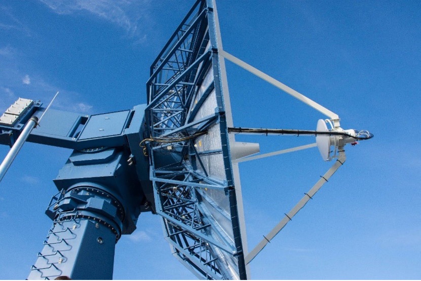
The dish antenna uses a parabolic reflector to collect signals from the spacecraft and focus them onto a feed antenna. The feed antenna is typically a horn antenna with a circular aperture. The size of a dish is at least several wavelengths in diameter at the frequency of operation and can be increased for higher gains. The distance between the feed antenna and the parabolic reflector can also be several wavelengths. For example, a Ka-band 34 m deep-space antenna with a feed distance of 15 m would be approximately 3,000 wavelengths for the dish diameter and 1,500 wavelengths for the feed distance, relative to a 1 cm Ka-band wavelength. The gain of a dish reflector (Figure 11.12) is frequency-dependent and directly proportional to the square of its diameter. Dish antennas are available in sizes ranging from 1 meter to 70 meters in diameter.
The antenna collects RF waves, and the antenna feed converts the electromagnetic waves into conducted RF electrical signals. The feed consists of a resonant pickup tuned to the transmit or receive frequency, a low-gain low-noise amplifier, a sharp filter, and a second LNA with higher gain than the first amplifier. These elements condition the signal. The signal then travels through a coaxial cable to a nearby location where a radio demodulates the RF signal into digital data. In the uplink direction, the radio modulates data bits onto an RF carrier, which is amplified to 10 W or more. The amplified RF signal is transmitted through the antenna feed, and the antenna radiates and focuses the electromagnetic waves towards the satellite.
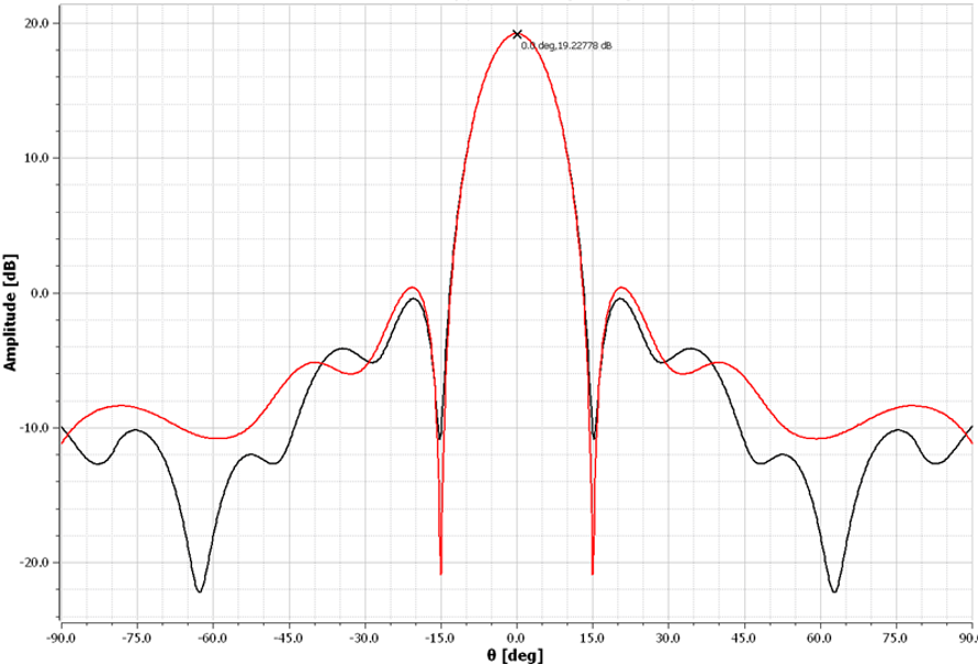
It is desirable to have high antenna gain; however, as the gain increases, the beamwidth decreases. There is a practical trade-off in which the beamwidth may become so narrow that tracking is difficult, or the antenna becomes so large that it is difficult to procure or manage. A typical antenna radiation pattern is shown in Figure 11.13. There is a main lobe where most of the transmitted energy is concentrated. The remaining energy is distributed in the sidelobes on either side of the main lobe. The reduced sidelobes are intentional to minimize reception of ground noise from terrestrial emitters and to limit interference to other systems during transmission. The blue arrows in the Figure indicate the full-width half-max gain point at about ±6°, corresponding to an allowable antenna pointing error of less than 6° and an effective gain of approximately 16 dBi for link budget calculations. If higher gain is required, the antenna size will increase and the beamwidth will correspondingly decrease.
Directional antennas point toward the satellite as it moves over the ground station. Pointing adjustments are required in both the vertical (elevation) and horizontal (azimuth) directions. These movements are accomplished using motors and gear systems. Tracking software is used to predict the satellite’s future position. The satellite position and time are processed through additional software that converts this information into commands for the antenna motor controller. Time is critical factor, and GPS time is used by the computer generating the satellite position estimate. A dedicated GPS receiver is connected to the computer for this purpose.
The cost of a DTE ground station is directly correlated with the aperture size, which drives the requirements for the ground station foundation, pedestal, motors, and gear systems. Yagi antennas are generally less expensive. They sustain lower wind loads and therefore can use smaller foundations for support. In contrast, dish antenna reflectors sustain comparatively high wind loading and therefore require stronger concrete foundations and larger motor and gearbox assemblies than Yagi antennas.
11.5.2 Component Hardware for Ground Systems (GS)
This section provides examples of GS components and supporting equipment. Table 11-10 lists representative products in each category. The antenna feed consists of the RF pickup, LNA, and mechanical filters located directly on the antenna. A radome is an RF-transparent enclosure that protects the antenna from environmental conditions.
| Table 11-10: Ground System Components | ||
|---|---|---|
| Product | Manufacturer | Type of Product |
| Tracking Antenna | Viasat, Safran | Antennas for small satellites in and S, X and Ka-band frequencies |
| Antenna Feed | See End-to-End Hardware Section 11.7.2 | RF pickup, mechanical filters, LNA |
| Radio, Software Defined | NI Ettus Research | USRP X410, up to 7.2 GHz with RFSOC advanced FPGA and meeting wide bandwidth requirements. USRP X310: DC-6 GHz with up to 160 MHz of baseband bandwidth, multiple high-speed interfaces |
| Data Receiver | Safran Data Systems | Cortex CRT (low data rate) and HDR (high data rate (previously by Zodiac) |
| Modem, for TT&C and Payload Reception | Safran Data Systems | Satcore, plug-and-play modem for TT&C and Payload Reception |
| Digital Processing | Kratos | SpectralNet: Digital IF product that converts analog signals at RF frequencies up to S-band into digital IF packets. |
| Radome | Infinite Technologies | Antenna radomes |
| Ground Station Dongle | GAUSS | A USB low-power board to simulate ground station in laboratory conditions. The USB dongle integrates both a low-power UHF transceiver and a TNC, thus miniaturizing common ground station rack systems |
| Integrated Testing Systems (EGSE) & Ground Station TT&C Modems | Celestia Satellite Test & Simulation | Hardware and software elements all operating within a single reference platform and environment |
| Tracking Antenna | SatRev S.A. | Antennas for small satellites in and UHF and S-band frequencies |
| Modem, for TT&C and Payload Reception | SatRev S.A. | UHF for TT&C and Payload Reception |
| Radome | SatRev S.A. | Antenna radomes |
Cortex HDR
Several NSN, SSC, and NOAA stations use the Cortex HDR High Data Rate Receiver, which performs demodulation, decoding, and frame synchronization on the X-band data stream. Each virtual channel in the AOS frame received by the station’s X-band receiving system is written into separate files. Files are separated into one-minute intervals for a single VCID, enabling faster turnaround time and smaller transmission units in case of transfer issues. File-based data is stored in a buffer (e.g., for 7 days) for retransmissions and failure recovery when necessary. At the end of a pass, ground stations such as NSN sites perform an automatic secure file transfer protocol (SFTP)/secure copy protocol (SCP) push to the customer. If the customer wants to “replay” a dataset, they may use the self-service SFTP/SCP interface to pull their data to their site. Alternatively, the customer may choose to manually retrieve files instead of using automatic file transfer.
USRP X310 and X410 Open-Source Software Defined Radio for SatCom Applications
The NI Ettus Research brand includes the Universal Software Radio Peripheral (USRP) family of products. The USRP is one of the most widely used open platforms for small satellite communications, with options ranging from high-performance to low-cost to highly deployable configurations. One of the most widely used hardware units for satellite communication applications is the USRP X310 with the UBX RF daughterboard. The USRP X310 is a high-performance software-defined radio capable of transmitting and receiving modulated signals. With up to 160 MHz of instantaneous bandwidth and a frequency tuning range up to 6 GHz, the X310 with UBX provides the raw hardware performance required for many ground station satellite communication applications. The USRP family supports a wide range of software toolchains, from LabVIEW to GNU Radio, with many existing IP modules for modulation and demodulation. The USRP X310 is intended for laboratory environments; however, it can be configured for rugged, weatherproof applications. Many small satellite researchers use the USRP as ground station equipment due to its adaptability with open-source software and its embedded FPGA preprocessing capability. The USRP X310 offers two channels, 10 GigE, and PCIe intergace, whereas the NI Ettus USRP X410 is equipped with dual 100 GbE interfaces capable of significantly higher data throughput (13).
Kratos OpenSpace SpectralNet
OpenSpace SpectralNet eliminates the distance constraints in RF transport by digitizing RF signals into standard VITA-49 or DIFI IP packets for transmission over IP networks while preserving frequency and timing characteristics, and then reconstructing the RF signals at their destination. By eliminating distance constraints between antennas and signal processing equipment, this technology enables operators to deploy new ground architectures with several advantages, including mitigating rain fade effects for Ku/Ka satellites, reducing costs through centralizing operations, simplifying disaster recovery and system maintenance, optimizing antenna placement, and enabling migration from hardware-based ground systems to virtual ground systems. SpectralNet performs these functions while protecting the operator’s existing investment in current equipment. In addition to removing distance constraints, digitizing RF signals into DIFI packets provides a pathway to virtualizing network functions such as modems and receivers that run on general-purpose computing platforms. For more information, see https://www.kratosspace.com/.
Integrated Testing Systems and Ground Station TT&C Modems
Celestia Satellite Test and Simulation (Celestia STS) provides ground-based solutions in satellite simulation, testing, communication, and data processing. Equipment is available in standard configurations or can be customized to meet specific mission requirements. These systems are typically deployed in AIT (Assembly, Integration, and Test) cleanroom environments or ground stations. Celestia EGSE solutions have been used in more than 80% of European Space Agency (ESA) missions.
Celestia STS develops ground-based satellite testing and communication systems and adapts its products to meet specific mission requirements. The company has extensive experience in ground segment engineering and is positioned to support evolving industry needs. Increasing demand for high-speed, secure data transmission is driving the adoption of optical communications for satellite-to-ground and inter-satellite links (7).
Infinite Technologies Radomes
A well-designed radome serves as a protective cover for an antenna while minimizing adverse effects on its electrical performance. Figure 11.14 illustrates an example of a radome supplied by Infinite Technologies. Radomes create a controlled environment for the antenna system, shielding sensitive equipment from environmental stresses such as wind, snow, ice, and salt spray. By protecting the antenna from these elements, a radome can extend its operational life and reduce maintenance costs.

Incorporating a radome early in the system design phase is important. Doing so allows the use of lighter and more cost-effective components, such as drive motors and foundations, because the radome eliminates wind loads on the antenna. Additionally, the controlled environment within the radome increases system availability, enabling the antenna to operate efficiently under harsh environmental conditions with minimal signal degradation. Maintenance personnel also benefit from the radome, as it provides protection from weather during antenna maintenance activities.
For a radome to be effective, it must be tailored to the specific requirements of the system it protects. A carefully selected and well-designed radome can enhance system performance and reliability by:
- Enabling operation in severe weather conditions by shielding the antenna from wind, rain, snow, hail, sand, salt spray, insects, animals, UV exposure, windblown debris, and extreme temperature fluctuations.
- Creating a controlled environment that minimizes downtime, extends component and system life, and supports more economical choices in antenna pedestals, foundations, and drive systems.
- Providing security and protection for the antenna system against observation, vandalism, and other threats.
11.5.3 Ground Software
Ground software visualizes and calculates the satellite location in orbit and controls the tracking antenna. Command and control software manages command scripts sent to the satellite and can display and analyze telemetry. Many software options are open-source and free. Other software may be purchased from companies with a long history in ground segment solutions that have previously provided hardware products to perform these tasks (Table 11-11).
| Table 11-11: Software for Ground Systems | |||
|---|---|---|---|
| Product | Manufacturer | TRL | Type of Product |
| softFEP | ARKA AMERGINT | 9 | Software commands and telemetry data processor handling formatting and interface conversion. Full support for NSA Type 1 crypto, AES encryption/decryption and CCSDS data links. |
| OpenSpace quantumFEP | Kratos | 9 | Software that performs data formatting and interface conversion for commands and telemetry, with full support for NSA Type 1 and AES encryption/decryption devices. |
| Gpredict | Alexandru Csete | 9 | Open-source software that tracks satellites and provides orbit prediction in real-time. Radio and antenna rotator control for autonomous tracking. |
| GNU Radio | GNU Project | 9 | Free software development toolkit that provides signal processing blocks to implement software- defined radios and signal processing systems. |
| HWCNTRL | DeWitt & Associates | 9 | Ground station control program with an automation software package. |
| Expedite | Remos Space Systems, AB | 9 | CPU-based software modem for telemetry, telecommand, and payload data over UHF–L-band links, featuring integrated mission scheduling and transmission sequence control. |
softFEP
ARKA AMERGINT softFEP applications are deployed virtually on cloud architectures or hosted on dedicated servers. The applications perform control center data formatting and interface conversion for commands and telemetry, with support for NSA Type 1 and AES encryption/decryption devices. SoftFEP applications are built on a proven library of more than 1,000 software components. This allows each softFEP application to be tailored to the specific requirements of the ground system. Processing chains configured via Python scripts move satellite downlink data from ground receipt for processing and route uplink data to the radiating site. Deployment of softFEP on multiple virtual machines (VMs) or within the cloud is inherent in the product architecture. Virtualized softFEP deployments support a wide range of ground system architectures while leveraging cloud-computing benefits. When applications are deployed in VMs, they can be hosted locally or run remotely in the cloud and interoperate across network connections. Customers have deployed softFEP applications as independent network gateways, black front-end processors, red front-end processors, and data recorders, flowing data between the VMs as a satellite contact is processed. Visit https://arka.org/ for more information.
quantumFEP
Kratos developed OpenSpace quantumFEP (qFEP) is a virtual front-end processor for TT&C. The system is designed to match the requirements, schedules, and budgets of quick-turn programs. qFEP connects C2 systems to RF signal processing equipment, handling command and telemetry stream formatting, encryption/decryption, CCSDS processing, and network interfaces to either quantumRadio (qRADIO) or third-party ground antenna networks. Supported deployment options include generic compute servers, virtual machine environments, bare-metal installations, or orchestration through Kratos OpenSpace Platform, and qFEP’s small memory footprint allows for more efficient use of system resources. In addition, the product achieves hardware independence by eliminating custom drivers, firmware, and hardware cards. Figure 11.15 illustrates the qFEP system architecture. For more information, see https://www.kratosspace.com/.
Key features of quantumFEP are:
- Pure software implementation for signal processing functions
- Support for CCSDS TC, TM, and AOS frame protocols, as well as Cadet, AX.25 and Reed=Solomon Encoding
- Suitable for a wide range of satellite programs
- Compatibility tested with widely used ground-station modems
- Built-in test functions reduce integration and test (I&T) effort and cost
- Configurable as mission requirements change or as new missions come online
- Commercial AES encryption/decryption standard feature with built-in AES key manager
- Standard TCP/IP, GEMS, REST, and VITA-49 interfaces support seamless integration
- Access and control from anywhere through the web, with no client software to install or maintain
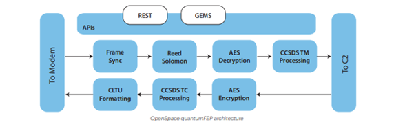
Gpredict
Gpredict is a real-time satellite tracking and orbit prediction application. It can track a large number of satellites and display their positions and other data in lists, tables, maps, and polar plots (radar view), as shown in Figure 11.16. It can also predict future passes and provide detailed information about each pass. Gpredict differs from other satellite tracking programs in that it allows satellites to be grouped into visualization modules. Each of these modules can be configured independently, allowing unlimited flexibility in the look and feel of the modules. It also allows satellite tracking relative to multiple observer locations simultaneously. http://gpredict.oz9aec.net/
The following are key features of the software:
- Fast, accurate real-time satellite tracking using the NORAD SGP4/SDP4 algorithms
- No software limit on the number of satellites or ground stations
- Appealing visual presentation of the satellite data using maps, tables, and polar plots (radar views)
- Allows satellites to be grouped into modules, each with its own visual layout and independently confirgurable; multiple modules can be used simultaneously
- Radio and antenna rotator control for autonomous tracking
- Efficient, detailed prediction of future satellite passes, with user-configurable parameters to support both general and specialized predictions
- Context-sensitive pop-up menus allow future passes to be quickly predicted by selecting any satellite
- Extensive configuration options that allow advanced users to customize both the functionality and look and feel of the program
- Automatic updates of Keplerian Elements from the web via HTTP or FTP, or from local files
- With a robust design and multi-platform implementation, Gpredict can be integrated into modern computer desktop environments, including Linux, BSD, Windows, and MacOS X
- As free software licensed under the GNU General Public License, it can be freely used, studied, modified, and redistributed
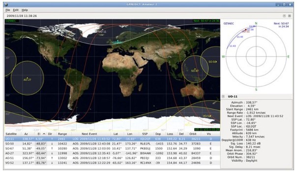
GNU Radio
GNU Radio is a free and open-source software development toolkit for developing radio systems in software rather than entirely in hardware. It can be used with readily available, low-cost external RF hardware and runs on most modern computers to create software-defined radios. It can also be used without hardware in a simulation environment.
GNU Radio performs signal processing and can be used to develop applications that receive data from digital streams or to transmit data into digital streams, which are then sent using hardware. GNU Radio includes filters, channel codes, synchronization elements, equalizers, demodulators, vocoders, decoders, and other elements (referred to as blocks) typically found in radio systems. It also provides a method for connecting these blocks and managing how data is passed between them. Blocks can be implemented in C++ or Python.
As GNU Radio is software-based, it handles only digital data. It operates on digitally sampled waveforms that can correspond to RF signals with digital or analog modulation. Typically, complex baseband samples are the input data type for receivers and the output data type for transmitters. Analog hardware is then used to shift the signal to the desired center frequency. Aside from this requirement, any data type can be passed between blocks, including bits, bytes, vectors, bursts, or more complex data types. GNU Radio supports heterogeneous computing, where some blocks run on an FPGA or GPU. These acceleration techniques are particularly important for processing large bandwidths or data rates, especially in embedded platforms where size and power consumption are usually constrained. Execution scheduling and data movement in heterogeneous environments are active areas of development and research in the GNU Radio runtime. GNU Radio can be used on embedded systems, such as ARM SoCs running Linux, as well as on more powerful desktop or server systems. GNU Radio is frequently used as part of ground stations, both for standard protocols such as CCSDS and for custom modems. Some commercial ground-station-as-a-service solutions that support GNU Radio modems include Azure Orbital Ground Station and AWS Ground Station. Another example is the open-source, community-driven SatNOGS network. GNU Radio is also useful for prototyping and laboratory testing. Additionally, some small satellites run GNU Radio on-board, typically as part of a flexible SDR payload. Figure 11.17 shows an example of a GNU Radio block diagram. For more information, visit wiki.gnuradio.org/index.php/Main_Page.
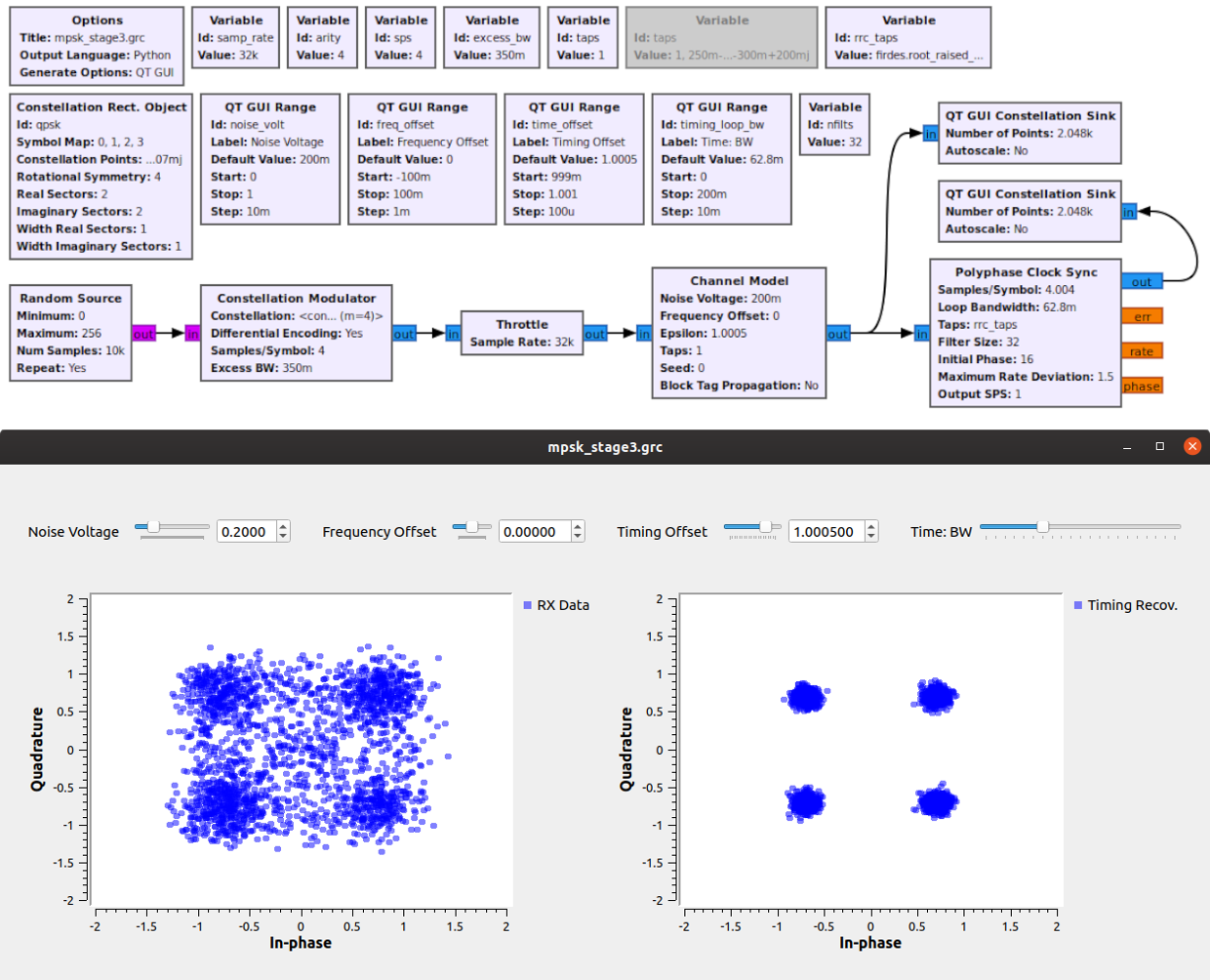
HWCNTRL
HWCNTRL is a satellite ground station control program installed on more than 30 sites worldwide. This automation software package supports multiple antennas and instruments simultaneously. Satellite passes are generated upon user request based on the ephemeris set, and users can select specific passes to add to the schedule. Scheduled events can be single-use or recurring on a daily or weekly basis. A control/status screen is available for each instrument in the system, and users can view and modify instrument settings through these screens. For more information, visit https://www.dewitt-assoc.com/groundStation.html.
Expedite
The Expedite software modem by Remos Space Systems performs real-time demodulation, decoding, encoding, and frame synchronization in compliance with CCSDS standards, and supports data exchange through TCP/IP, REST, WebSocket, and FTP interfaces. As the central control unit, Expedite directly manages the sequencer, which coordinates signal routing, timing, and safety interlocks. The sequencer controls high-power amplifiers (HPAs), low-noise amplifiers (LNAs), and RF switches to support both half- and full-duplex communication modes, ensuring safe and synchronized operation during transmit and receive transitions. Expedite is compatible with widely used small satellite transponders including GomSpace AX100 and X2150, Clyde Space, EnduroSat, and ISIS, and is used across government, commercial, and academic ground stations worldwide. For more information on Remos Space Systems, please reach out to info@remosspace.com.
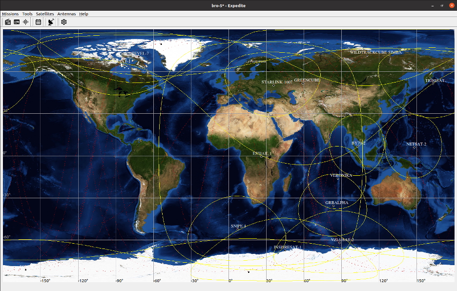
11.6 Mission and Science Operations Centers
The Mission Operations Center (MOC) is where satellite commanding is generated, ground station control is managed, and telemetry is archived. It is typically a physical location where the resources required to operate the satellite is located. It is often located in a secure room with controlled access to protect the satellite operating equipment and prevent unauthorized control. The room typically contains several terminals, allowing multiple subsystem experts to review telemetry or run analysis programs concurrently. An example of a MOC with multiple terminals is shown in Figure 11.19.
The size of the MOC is determined by mission complexity. More personnel are present during critical events or when resolving anomalies. For a SmallSat mission, complexity is typically lower, and the MOC is correspondingly smaller. In addition to the terminals and telemetry analysis software, other resources are used to manage the satellite. These may include physical models of the satellite used to study anomalous telemetry. In the case of CubeSats, a functioning spacecraft engineering model may be used to test commands and reproduce anomalies.
All tasking requests for future satellite operations are managed by the mission operations team. The team generates command plans, simulates satellite response to verify those plans, and, if confidence in the simulations is insufficient, executes the commands on engineering model hardware prior to approval for upload. The MOC team also manages downloads. They determine the availability of ground resources. If the MOC does not own its own ground stations, a contact request is submitted to the ground station provider. The MOC submits data required for satellite commanding, including commands and payload parameter settings, a schedule of events for the flight computer, and ephemeris and pointing tables for the attitude control system, along with a mission timeline. After contact, data are returned to the MOC by the ground station.
Prior to launch, rehearsals are conducted with all personnel at their stations, using simulated telemetry with inserted anomalies to test the team. This ensures readiness with the appropriate analysis software and integration test data to quickly diagnose issues and propose corrective actions. At the time of launch, the MOC is fully staffed, as this is a critical event. Telemetry must be interpreted and acted upon quickly.
The Science Operations Center (SOC) is the focal point for all mission science data. The science team uses it to store and analyze data. From this analysis, the science team generates satellite tasking requests that are sent to the mission operations team. External requests for additional data collection are first evaluated by the science team to assess feasibility before tasking requests are submitted to the operations team.
The SOC is typically separate from the MOC. The payload developer typically maintains a separate operations center at their facility with access to supporting resources. Before cloud-based storage, the SOC was a physical location where data servers resided to archive mission science data. Prior to secure network solutions, dedicated computers within the SOC ran programs specifically designed to analyze science data. If the mission was secure and the data classified, the physical SOC was protected with restricted access. Missions that do not produce classified data can take advantage of a virtual SOC, where science data and analysis tools reside in the cloud. A virtual SOC allows scientists to access data remotely without requiring a physical location. As cyber security techniques improve, more secure missions may adopt virtual SOC architectures, with only highly classified missions maintaining secure physical SOCs.
11.6.1 Software for Mission Operations
Mission operations rely on software across all elements of the ground segment. Figure 11.20a outlines software functions for each element. Satellite flight software manages state-of-health telemetry, payload data, and interfaces with ground segment software. Figure 11.20b provides an example of command and telemetry data flow for a mission using DTE and relay services. Transmission can begin autonomously by programming the satellite to recognize when it is over a ground station or within view of a relay satellite. Transmission can also be triggered by a command from a ground station or relay satellite. When a communications link is established, the radio enters a higher-power transmit mode and sends the data. The flight software manages data flow into and out of the radio, ensuring buffers do not overflow. It formats housekeeping and science data into packetized formats compatible with ground station requirements. Ground networks use established data protocol standards. For example, NASA’s NSN incorporates standards proposed by the CCSDS. The flight software unpacks received packets to retrieve uploaded commands and data.
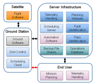
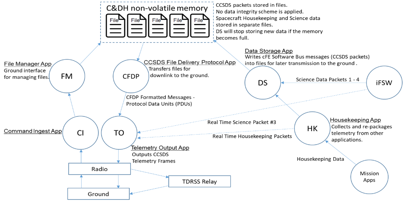
Software supporting the ground segment exists onboard the satellite, at the physical ground stations, and within the MOC (including server infrastructure and end-user applications). Ground stations use software for antenna control, command generation, signal formatting and encoding, pass scheduling, and MOC interfacing. One software computes pointing direction using Two-Line Element (TLE) data, a mount model, and GPS time. It generates time-based motor control commands. The motor controller executes these commands to track the satellite during a pass. During the pass, another software suite monitors the link, processes and encodes commands, handles signal formatting or encryption, and demodulates and decodes received transmissions. This software also manages the network connection with the MOC, including TLE updates, data uploads, and data retrieval requests. After contact, received data are transferred back to the MOC. The ground station may also generate its own telemetry for contact. This data is used to trend system performance. Performance trending provides insight into degradation for both the satellite and the ground station. Ground stations may also use scheduling software when supporting multiple missions. This software uses orbit simulation and current TLE data to determine expected contact times. It identifies conflicts between contact opportunities and assists with schedule optimization. A schedule is generated for a given period and is programmed into the ground station control system for execution. This process can be automated, but an operator typically monitors the system.
Mission planning software in the MOC is required for missions involving complex satellite behavior, such as target pointing during science data collection. The software includes models of satellite dynamics and component capabilities. Events are planned as sequences of actions executed in a defined order with estimated timing. The software simulates satellite response, and actions and timing are iteratively adjusted to optimize performance and avoid fault conditions. The output includes all commands and databases required by the satellite. This output is submitted to ground station ingest software for upload prior to the planned event.
The SOC uses software to handle the receipt, unpacking, reconstruction and post-processing of mission science data. Using an ISS payload as an example, science data are downlinked via TDRSS to NASA Marshall Space Flight Center (MSFC), where they are separated into science streams and routed to the appropriate payload SOCs. At the SOC, a computer outside the company firewall continually operates to receive data from MSFC. On this computer, NASA-provided TReK software manages data transfer by interfacing with MSFC systems. The science team retrieves the data and transfers it securely through the corporate firewall into the SOC. The science team develops parsing software to unpack data stored in CCSDS format. Additional software reconstructs the original payload data products (e.g., images). Further processing software generates post-processed data products that are archived and distributed to users. Common programming languages for these applications include Interactive Data Language (IDL) and Python.
11.7 End-to-End Communications and Compatibility Testing
A SmallSat undergoes various tests throughout its development cycle to verify proper functionality. For the communication subsystem, end-to-end communication and compatibility testing with the selected ground network is the most critical test. Compatibility testing verifies that the ground station can properly communicate with the satellite on the uplink and downlink RF channels. Ideally, compatibility would be validated by testing the flight spacecraft with the actual ground station that will be supporting the mission. This may not be practical for larger or high-cost satellites, due to logistics associated with shipping and risk of damage. Two alternatives to shipping the satellite are typically used. One option is to include sending a replicate set of ground station hardware to the satellite facility for testing. A second option is to test with only the flight radio or an ETU radio (also common to include the flight computer) at the ground station or at a test lab configured with the ground station hardware. Drawbacks to these alternatives include not testing the exact command path or determining whether ground sensitivity is sufficient.
For CubeSats, it is commonly feasible to bring the CubeSat to the ground station for testing. If that is not feasible, then at a minimum, the radio and flight processor (or Engineering Development Units (EDUs) should be used. Testing at the ground station allows for the entire equipment chain to be part of the test, including the low-noise amplifier (LNA) and transmit/receive switch, if used. It is desirable to initially test in a closed-loop configuration, where the satellite is connected to the ground system at the antenna port via a cable (with appropriate attenuators in line). If the satellite is fully integrated, disconnecting the flight antenna may not be feasible. In this case, a small monopole antenna located indoors near the CubeSat can be connected to the ground system. The monopole antenna connection to the ground system may vary depending on the ground antenna configuration but should include as much of the ground system electronics as practical.
Some missions include an outdoor open-loop test with the CubeSat and ground antenna. This method allows for the entire ground system, including the ground antenna, to be included in the test. However, the ground antenna typically cannot point directly at the CubeSat due to mechanical limitations or to limit the received signal so ground system RF components are not overdriven. Off-pointing and reflections from the ground and local structures can also make it difficult to achieve a valid test.
End-to-end network testing primarily validates the ground station to MOC interface. This test verifies that the MOC can properly receive downlink data from the ground station and that the ground station can receive and process uplink command data. Initial end-to-end testing will validate network connectivity, showing that network connections can be established and firewall rules at the ground station and MOC are in place. Once network connectivity is established, the MOC can transmit commands to the ground station for capture. The ground station can then transmit simulated or recorded data to the MOC for validation.
It is preferable to conduct initial end-to-end network testing prior to compatibility testing. In cases where the satellite can be brought to the ground station, a full end-to-end test can be performed. Command transmissions from the MOC, through the network and ground system to the satellite can be validated. A complete end-to-end telemetry dataflow from the satellite to the control center can also be validated.
11.7.1 End-to-End Hardware for Ground Systems
A complete ground system can be provided as a kit with all the necessary components bundled together and set up to work seamlessly. These end-to-end solutions include the antenna, its controller, and the RF feed with all the necessary filtering and low-noise amplification for the particular frequency of interest. They use a software-defined radio or a dedicated transceiver to convert between digital packets and RF waveforms. Software is included to process the satellite position and direct the antenna to track it. Additional software is used to archive and display the information within the digital packets. Three vendors, GAUSS, Innovative Solutions In Space (ISISPACE) and GomSpace, listed in Table 11-12 provide solutions for the low-cost CubeSat and small satellite market. One vendor, Surrey Satellite Technology Limited, offers a higher-end system, installation services, and personnel support. The final vendor listed, Kratos, offers a different end-to-end solution that begins with a digitized RF waveform. The Kratos Quantum software then demodulates, filters, unpacks, parses, displays, and archives the data.
| Table 11-12: End-to-End Hardware for Ground Systems | ||
|---|---|---|
| Product | Manufacturer | Type of Product |
| Complete Ground Solution | GAUSS | Small satellite provider offering a complete ground solution. UHV, VHF, and S-band |
| Complete Ground Solution | ISISPACE | Small satellite provider offering a complete ground solution. UHV, VHF, and S-band |
| Complete Ground Solution | GomSpace | Small satellite provider offering a complete ground solution. UHV, VHF, and S-band |
| Surrey Ground Segment | Surrey Satellite Technology Ltd. | Major contractor offering a complete ground solution. S-band uplink/downlink and X-Band downlink capability |
| Quantum | Kratos | Major contractor with a complete ground solution |
| Expedite Turnkey Ground Station | Remos Space Systems, AB | Integrated ground station solution combining software-defined modem, automation sequencer, and multi-band antenna system for end-to-end satellite telemetry, telecommand, and payload data operations across UHF, VHF, S-, and L-band links. |
| Complete Ground Solution | SatRev S.A. | Small satellite provider offering a complete ground solution. UHV, VHF, and S-band |
GAUSS Ground Station Kit
The GAUSS ground station is a turnkey solution. It can be configured with UHF, VHF and S-band on the same pointing system. An example of the associated hardware is shown in Figure 11.21.
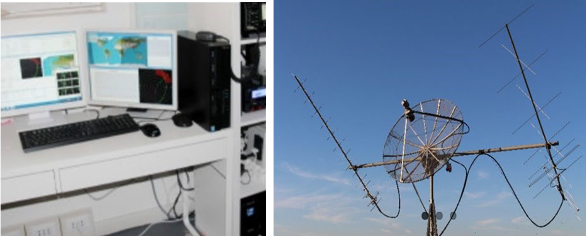
Hardware features of the systems offered include:
- High gain Yagi-Uda VHF and UHF antennas (>16 dBi for UHF)
- Low-noise amplifiers and band-pass filters for VHF and UHF bands
- Low-loss RF coaxial cables
- 1.5-meter parabolic dish for higher frequencies downlink (up to 6 GHz, default feed is for S-band)
- VHF: uplink and downlink up to 100 W using radio and Terminal Node Controller (TNC), software-defined radio (SDR) optional
- UHF: uplink and downlink up to 70 W, using radio and TNC, SDR optional
- TX using ICOM-9100 hardware, RX recording and decoding via SDR
- Several RF and electrical fuses for lightning protection
- S-Band: downlink using SDR for recording and post-processing of I/Q RF data
- Az/El rotor for high-torque maneuvering
- Hardware components power switch on/off to minimize power consumption
- Full HD camera for instant antenna monitoring and picture logging
The features of the software that accompanies the system include:
- Automatic TLE download from publicly available repositories
- SGP4 propagator as suggested by USAF NORAD’s Space-Track
- Rotor control (compatibility with several rotor controllers, e.g. Yaesu, RF Hamdesign)
- Assisted rotor pointing calibration and verification using Sun position
- Fully compatible with ICOM-9100 satellite radio and GAUSS USB ground dongle
- Separated Doppler shift corrections for uplink and downlink frequencies
- DUPLEX TX/RX mode
- Instant weather check and logging to operate the ground station safely
- Lightning detection for safe antenna operation
- Instant logging of all subsystems operation
- Ground map with live Earth clouds
- Compatible with several TNCs (Kantronics, Symek, Paccomm, Kenwood)
- Email report to ground station operators
- Instant email alerts for non-nominal conditions of the satellite or GS hardware components
- Session programming for weeks of unattended ground station operations
- GUI command recording for easy session programming
- One button programming to include a whole set of commands in the session
- Manual override during pass for last-minute command addition
- Control and handling of multiple satellites using configurable priorities
- Satellite TLM decoding, graphing, and archiving into a database accessible by web
- Integrated satellite payload data handling and decoding (e.g., for image file processing)
- TCP/IP connections for remote ground station and TNC operations
For more information, visit www.gaussteam.com/services/ground-station/.
Innovative Solutions In-Space Ground Station Kit
The ISISPACE small satellite ground station is a low-cost, turnkey solution that is designed to communicate with satellites in low-Earth orbit that operate in either amateur frequency bands or commercial bands. The frequency bands covered are S-band, UHF, and VHF. The ground station consists of an antenna and a 19-inch rack which houses the transceiver, rotor control and computer which make the system very compact. Examples of these components are shown in Figure 11.22. The transceiver makes use of an SDR that provides flexibility to swiftly reconfigure modulation/coding/data-rate in real time. Most commonly used modulation schemes and coding methods are already implemented, and any customization requests can also be handled. For more information, visit www.isispace.nl.
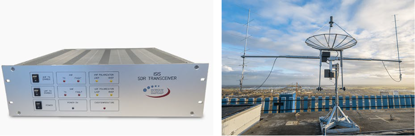
GomSpace Ground Station Solutions
GomSpace offers two products (A) NanoGround, and (B) Hands-off Operations Platform (HOOP) that can be used as ground segment building blocks for a wide variety of missions.
- NanoGround provides a communication gateway for spacecraft using GomSpace AX2150 and NanoCom Link S/SX S-band and X-band radios. NanoGround provides a TMTC link over S-band as well as IP networking over S and X-bands and is designed to be easily integrated with commercial ground station service providers. As of September 2024, NanoGround offers built-in integration for KSAT’s ground station network. AWS Ground Station and LeafSpace ground station network support will be available in the near term. Other ground station networks are being considered and can be discussed based on client need. https://gomspace.com/product/nanoground/
- HOOP is GomSpace’s Mission Control software solution, providing autonomous “hands-off” satellite operations for single spacecraft and constellations. HOOP can either be operated by GomSpace’s Mission Operations Team for client missions or it can be purchased by clients on a subscription basis to manage their own missions. HOOP comes pre-built with integration for GomSpace NanoGround, providing an out-of-the-box solution to operate missions flying GomSpace satellites. HOOP’s capabilities will be expanded in the near term with an upcoming release to support CCSDS communication protocols. This expanded capability will allow HOOP’s application domain to include third-party satellites. HOOP has been in operation since 2020 and currently manages LEO missions. As of September 2024, five additional HOOP missions are in development and planned for near-term execution. https://gomspace.com/hoop.aspx
Surrey Satellite Technology Ltd. Ground Station Kit
Surrey can provide complete turnkey ground segment solutions for a range of space platforms, including all the hardware and software necessary to operate, maintain, process and archive data. Services provided by Surrey include:
- S- and X-band ground stations with full motion antenna systems from 2.4 meters to 7.3 meter in diameter, with radome options available for harsh climates
- SSTL Pilot Satellite Control Software
- Mission planning systems
- Radiometric and geometric image processing
- Data storage solutions
- Site surveys, ground segment installation and training
- Technical and maintenance support packages
In addition, Surrey can work with customers to integrate their ground segment solutions with existing ground infrastructure or with third-party ground station networks. For more information on Surrey Satellite Technology, visit https://www.sstl.co.uk/contact-us.
Kratos Ground Station Solutions
Kratos virtual ground solutions begin with the OpenSpace SpectralNet digitizer converting analog signals at RF frequencies up to S-band into digital IF VITA-49 or DIFI IP packets. Kratos Quantum virtualized network functions (VNFs) such as quantumReceiver (qRX) or quantumRadio (qRadio) then process the digitized RF waveform. Kratos virtualized network functions run on general-purpose compute and can be dynamically instantiated for different mission directives like mission data downlink and TT&C at the click of a button. Figure 11.23 provides a visualization for the system concept.
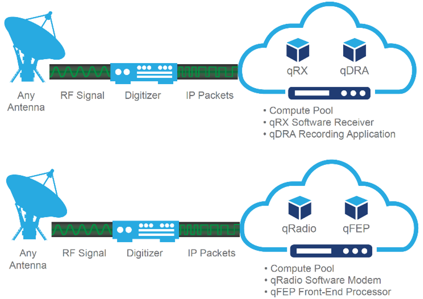
All components are available separately to support an existing C2 solution or third-party ground network with existing signal processing and antenna resources. The quantum products include:
- quantumCommand (qCMD), COTS software application for command and control (C2) of small spacecraft;
- quantumFEP (qFEP), connects C2 systems to RF signal processing equipment: handling command and telemetry stream formatting, encryption/decryption devices, CCSDS processing, and network interfaces to either qRADIO or third-party ground antenna networks;
- quantumRadio (qRadio), the software modem for RF signal processing on-premise or in the cloud;
- quantumDRA (qDRA), a data recording and archiving application supporting CCSDS/non-CCSDS header and channel data routing with IP-based interfaces;
- quantumRX (qRX), a fully virtualized wideband software receiver, specifically tuned to streaming Earth observations in near-real time with 500 MHz bandwidth using Digital IF digitizers;
- quantumTX (qTX), a fully virtualized wideband software transmitter, specifically tuned for Earth observation and remote sensing satellites with over 1 Gbps throughput for uplinks.
In 2021, Kratos introduced a virtual, software-defined architecture solution called the OpenSpace Platform. As an enterprise level end-to-end system, it provides satellite operators and service providers the flexibility to scale on-demand as their operations grow in size and capability. By leveraging Digital IF over IP with time-deterministic latency and software defined networks, the platform allows virtualized functions such as modems, channelizers, recorders and combiners to be orchestrated on generic servers in a ground station or public or private cloud environment. The virtual architecture lends itself to upgrades and/or updates automatically, ensuring ongoing reliability and security. In addition, the ability to test software releases in real time allows ground equipment functions to be included in continuous integration and continuous delivery cycles. Software-defined architectures are more agile, programmable, and automated, enabling the ground system to work in tandem with dynamic satellite payloads. By shifting from RF signals and analog equipment to a virtualized, IP-based infrastructure, orchestration can occur dynamically. Figure 11.24 illustrates the OpenSpace architecture concept. For more information on Kratos’ solutions, visit https://www.kratosdefense.com/contact.
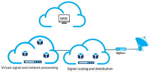
Remos Space Systems
The Expedite Turnkey Ground Station by Remos Space Systems is an integrated ground segment solution for UHF, VHF, S-, and L-band satellite communications. It combines the Expedite software modem (in Section 11.5.3), a sequencer, and a multi-band antenna system to provide a complete platform for telemetry, telecommand (TM/TC), and payload data operations. The system is intended for small satellite missions, academic institutions, and government programs requiring a compact and deployable ground station. Figure 11.25 below illustrates the Expedite turnkey solution.
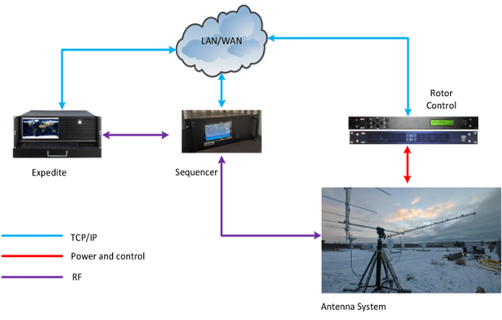
The turnkey configuration allows rapid installation and operation with minimal infrastructure. It includes mission scheduling, automated antenna tracking, and remote control capabilities. The system can function as a standalone unit or integrate within GSaaS networks. Typical applications include commercial and research satellite operations, academic training programs, and demonstration missions for emerging space nations. For more information on Remos Space Systems, please reach out to info@remosspace.com.
11.8 Cyber Security
Security for a space system must address all mission elements—the flight platform, payloads, ground segment, and supporting services—because attackers can target any portion of the system-of-systems. The most accessible path for a remote adversary is typically the end-to-end command path, whether by injecting signals over the RF uplink/downlink, subverting transport networks (space or ground), or compromising command authority (e.g., operations centers). External dependencies (e.g., GNSS/PNT services, ground stations, external data providers) can also be manipulated to create mission impact. Jamming and denial of service against command/telemetry flows, as well as exploitation of vulnerabilities in any subsystem or component, can lead to system-level effects. These risks require early, risk-based, cybersecurity informed engineering carried from pre-Phase A through mission termination, consistent with U.S. policy and NASA requirements.
11.8.1 Minimum Protections for Command Authority
NASA missions shall protect command authority using authenticated encryption from the point of command generation to the spacecraft. At a minimum, cryptographic modules shall meet FIPS 140-3, Level 1 (or successor) and use FIPS validated algorithms and authenticated modes (e.g., AES-GCM) consistent with NASA-STD-1006A Space System Protection Requirements (SSPR 1). Where backup command links are used, authentication shall be enforced at minimum on those backups (SSPR 2). Projects shall treat command link CPI as CUI and protect it per NASA policy (SSPR 3).
Implementation note (non normative): CCSDS guidance documents provide protocol level security options for protecting telecommand and telemetry (e.g., integrity, authentication, confidentiality) and should be applied commensurate with mission risk. See CCSDS 350.0 G 3 The Application of Security to CCSDS Protocols and CCSDS 350.7 G 2 Security Guide for Mission Planners.
11.8.2 Resilience to External Dependencies (GNSS/PNT and Ground Infrastructure)
Space systems shall be resilient to the complete loss or temporary interference of external PNT sources (e.g., GNSS) consistent with SSPR 4. Recommended practices include multi-constellation GNSS, autonomous fallback navigation modes, and filtering and anomaly rejection in flight/ground software (e.g., Kalman filtering; rejection of out-of-family position/velocity/time changes; ignoring GNSS in known jamming zones; automatic receiver reset/recovery). Ground segments should capture GNSS quality metrics (e.g., C/N₀, DSA, PRNs tracked/available) and jamming/spoofing indicators in telemetry and operations logs to support detection and triage activities.
11.8.3 Defense in Depth (On Board and Ground)
Because external protections can be bypassed, projects should adopt defense-in-depth measures across flight and ground segments, including:
- Secure boot and runtime integrity checks; cryptographic verification of onboard software/firmware; compartmentalization/segmentation of critical functions to limit lateral movement.
- Onboard intrusion detection/response proportional to platform SWaP and risk.
- Ground operations security controls: unique user logons, least privilege access, segmentation/isolation of critical networks, strict command database protections (no hardware/backdoor/firecode commands that bypass authentication/encryption), and validation gates for critical commanding (time-based checks, user approvals, execution delays, pre-execution re-validation, comprehensive logging).
Reference practice: Align system security engineering with NIST SP 800-160 design principles (Appendix F) and integrate them in the systems engineering lifecycle, ensuring threats are addressed through architecture, design, implementation, verification, and operations.
11.8.4 Supply Chain Risk Management (SCRM)
Projects shall implement supply chain assurance commensurate with risk, covering hardware, software, and services. Recommended additions include:
- SBOMs for all flight/ground software and third-party components; continuous vulnerability monitoring.
- Verification of cryptographic module validation (FIPS 140-3) or documented equivalence for space-qualified implementations; secure firmware update processes with authenticity checks.
- Vendor sourcing/manufacturing transparency and repeatable, deterministic processes; added scrutiny of tiers and integrators.
11.8.5 Continuous Monitoring, Detection, and Incident Response
Ground systems should deploy real-time anomaly detection for command, telemetry, and network traffic with SIEM integration and mission-specific playbooks. Projects, spectrum managers, and operations centers shall report unexplained or suspicious interference (RF or cyber) per NASA-STD-1006A (SSPR 5/6) to the Agency focal point (MRPP) and other designated organizations, enabling enterprise-wide triage and response (9).
11.8.6 Policy and Standards Context
U.S. policy calls for risk-based, cybersecurity informed engineering and capabilities to retain positive control of space vehicles. Projects should leverage widely adopted best practices and norms (e.g., NIST CSF, CCSDS security guidance) and integrate security early in mission planning (10)(11)(12)(13)(14).
11.9 State-of-the-Art – Ground Data and Supporting Systems
11.9.1 Technologies
Multiple Spacecraft Per Aperture
The Annual Small Satellite Conference on the grounds of Utah State University is the premier event amongst small satellite stakeholders, and its themes reflect the trends of the times. As scientists are increasingly interested in characterizing fields (going beyond single-point measurements) requiring swarms of satellites, as well as the emergence of Distributed Satellite Missions (multiple satellites working in concert towards one common goal), MSPA is a critical enabler. While it is not a new concept, few ground stations have invested in such upgrade. The DSN has the capability to track multiple spacecraft per antenna (MSPA) (up to four) if they are all within the scheduled antenna’s beamwidth. The 34 m antennas at each complex can be combined into an array, with or without the co-located 70 m antenna. The combined G/T depends on several factors but is approximately increased by the sum of the antenna areas from the arrayed apertures minus approximately 0.3 dB of combining loss. For instance, arraying four 34-meter antennas results in an increase of 5.72 dB.
Automation and Modeling
The MOC of the future will include a “lights out” or fully automated option. This requires software on the ground station side to run the antenna automatically. Automation software will receive a list of times that the antenna should track the satellite and manage that list. It will send TLEs and data to the antenna with no one present, receive downlinked telemetry, and archive the data. Software automatically parses the telemetry, compares key watch items to defined limits, and alerts the team via email or phone text message. FreeFlyer by AI solutions combine astrodynamics/ spacecraft propagation, coverage and contact analysis (including swarms), attitude and maneuver modeling, and orbit determination (20).
Large Ground Antennas: to the Moon and Beyond
For years there has been a gap between NSN’s largest 18m and DSN’s 34/70m antennas, and such large antennas were not available from commercial ground providers. This gap has now been filled.
In 2022 Viasat introduced new 19/24m aperture antennas (Figure 11.26) at their Antenna Systems campus in Duluth, GA supporting several ongoing programs. The size and architecture of these larger apertures support current programs while offering the flexibility and scalability to support future and forward planning missions (18).
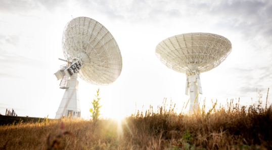
NASA Lunar Exploration Ground Sites
SCaN has announced Lunar Exploration Ground Sites (LEGS) to provide direct-to-earth communication and navigation services for missions operating from 36,000 kilometers (km) in the GEO to cis Lunar and other orbits out to 2 million km. To fully support distant orbits there will be three LEGS sites evenly spaced around the Earth. The Ground sites use CCSDS Modulation and coding schemes for forward and return data. Specialized/unique Mod-Cods are optional. User Local Equipment on-site is optional. The 18m assets are listed as White Sands, USA: 32.544863, -106.612504 Matjiesfontein, South Africa: -33.231224, 20.58163 (TBD) and Pacific Region TBD. MSPA is planned for up to 4 simultaneous return services per aperture (Max 3 for Ka). Use of LEGS for other than Artemis support is TBD. See Table 11-13 for projected performance of LEGS assets.
| Table 11-13: Projected Performance of LEGS Assets Pending Finalization | |||
|---|---|---|---|
| RF Performance Criterion | Radio Frequency Performance (Return) | ||
| S-Band | X-Band | Ka-Band | |
| G/T (minimum) | 28 dB/K | 39 dB/K | 47.5 dB/K |
11.9.2 Ground Aggregators
Table 11-14 lists those Ground Service providers who own and/or operate their own brand of ground assets. Irrespective of the nature of ownership, satellite operators are reliant on the limited ground stations they have access to. Satellite operators have well defined windows for exchanging information with their satellites. To meet evolving demand from within the fast-growing segment of the space industry, multiple aggregator models have emerged from private market participants. Services from companies such as RBC Signals, Infostellar, Amazon Web Services, and Spaceit are offered through specialist ground station capacity aggregator platforms. These are digital solutions enabling ground station operators to provide their excess capacity to a global user base. Since this is very similar to the business model of Uber, these aggregator services represent the ongoing “Uber-ization” of ground station services within the space industry. The downstream service markets are observing new players with new products and services. With increasing competition, the differentiating factors are shrinking in number. When the upstream capabilities start resembling each other, the key differentiators will include the ability to communicate with the satellites on-demand (19).
RBC Signals
RBC Signals is a provider of global satellite data communication products and solutions. It offers secure space communication solutions in every major frequency band using a worldwide network of company-owned and partner-owned ground systems. RBC Signals delivers dynamic solutions offering affordability, flexibility, and resiliency. Its diverse products and services offer complete end-to-end solutions for best-in-class multi-network solutions (see https://rbcsignals.com).
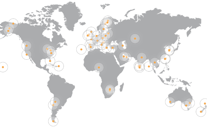
RBC Signals has aggregated a growing network of over 90 antennas in nearly 60 locations worldwide offering extensive capabilities. A map of these locations is shown in Figure 11.27. As of 2025, RBC Signals owns about 30% of the ground stations, and the rest are partner stations. For those needing turnkey access to existing antennas, RBC Signals offers ground station antenna-as-a-service with the flexibility to secure unlimited satellite passes (“core”) or ‘pay-by-the- pass/minute/GB’. This is made possible through a combination of their own network of highly capable systems and the unique “sharing economy” model, wherein they leverage the unused excess capacity of dozens of partner-owned antennas worldwide. RBC Signals provides turnkey bring-your-own-antenna hosting solutions, enabling customers to pair their own equipment with robust, high-end ground infrastructure virtually anywhere in the world. The company uses a distributed compute architecture where most processing is handled in the cloud or at a data center and some processing occurs either on the satellite or at the terrestrial edge near the ground station. It also supports on-premise cloud infrastructure from providers like AWS and Microsoft, along with virtual server hosting at the ground level. Expanding its offerings, RBC Signals recently introduced Go.BIC, a new intersatellite link service developed in partnership with IQ SpaceCom and Viasat (20). RBC Signals entered into a global agreement with Viasat to enable dynamic leasing of L- and Ka-band spectrum, supporting downlink from spacecraft in GEO to LEO space for emerging IoT applications. The company is also funded by the ESA under the STORM (Spectrum Trading and Operations for Radio-frequency Management) program to advance spectrum trading, sharing, and dynamic allocation technologies that optimize space-to-ground communications.
| Table 11-14: Service Providers for DTE Ground System Network | |||
|---|---|---|---|
| Product | Dish Sizes (m) | Services | MSPA |
| ATLAS Global Network | Various partners with other stations | S-band, X-band, UHF (Ka-band in 2017) Built on AWS cloud infrastructure | Partner dependent |
| KSAT and KSATLITE by Konsberg Sat. Services | > 10 part of NSN or 3.7 (KSATLITE) | X-band and S-band D/L and S-band U/L. VHF, UHF, Ka-band D/L. KSATLITE designed specifically for SmallSats | No |
| SSC Infinity by Swedish Space Corporation | 13, 7.3 NSN partner | Designed specifically for SmallSats; Uses standardized HW | Not found |
| AWS Ground Station by Amazon | 5.4 | Built on AWS cloud infrastructure | Not found |
| Viasat | 7.3, 5.4 | Global network operating in S, X, and Ka-bands that can reach LEO, MEO, GEO, and HEO orbits | Mission Dependent |
| Leaf Space | 3.7 | Standardized global network accessible through UHF, S, X and Ka-band | Yes |
| NASA, Near Space Network | 9 to 11, & 5 | Global network operating in S, X, and Ka- bands that can reach LEO, GEO, HEO, and Lunar orbits; up to 2 mil km | Legacy: NoLEGS (18m): planned, Yes |
| NASA/ JPL, Deep Space Network | 34, 70 | Operating at S, X, K, Ka bands. Includes Morehead State 21m in X-band. 8 m optical receive aperture planned for 2030s | Yes |
| NASA UHF Ground Station | 18 | Operates in UHF (400 – 470 MHz) | No |
| RBC Signals Global Ground Station Network | 24 to 33 | VHF, UHF, S, C, X, Ku, and Ka-bands | Partner Dependent |
11.9.3 Scheduling and Mission Operations Software
With the growing number of ground operators and aggregators, to take advantage of the plethora of assets, scheduling is emerging as the single most important enabler. As individual providers may have their own scheduling formats, for seamless operations, a common scheduler is critical, and this is true for NASA’s commercialization efforts as well.
Mission operations and ground support suites must also use software and systems for testing, and to monitor, command, control, and communicate with the spacecraft, as well as display status and disseminate data across all aspects of a space mission (including spacecraft performance and procedures, systems health, science and technology data handling and management, and telemetry tracking and control functions). For smaller spacecraft and missions, it is usually best to use the same ground support software for mission operations, integration and testing, and development and testing activities. There are numerous open-source and proprietary tools and programs available for these activities.
Scheduling: InfoStellar
InfoStellar offers communication services in the VHF, UHF, S, X, and Ka bands. Table 11-15 lists the frequency bands offered by InfoStellar which can be filtered by the tool available on their website. Figure 11.28 shows all 34 antennas on the platform that are either live or for which integration is planned or underway. With multiple commercial small-satellite operators in the market, the need for enhanced mission operations is now much more than an industry-wide requirement.
| Table 11-15: Select Frequency Bands by InfoStellar | |||
|---|---|---|---|
| Downlink | Uplink | ||
| X Band 8 – 12GHz | S Band 2 – 4GHz | S Band 2 – 4GHz | UHF Band 300MHz – 1GHz |
| Ka Band 27GHz – 40GHz | None No Uplink Channel | VHF Band 30 – 300MHz | None No Uplink Channel |
The following section provides an overview of mission operations and scheduling software products that can be integrated into a MOC (see Table 11-16). While the specific aspects of each of these products are discussed below, they all have some common features. In general, these software applications cover functions related to mission scheduling and tasking, commanding and telemetry, and monitoring and control. Many of them also have automation features that enable “lights-out” operations or reduced staffing requirements.
All these products are highly customizable. They can not only adapt to multiple missions, satellites, and ground stations, but they also allow for customized visualizations, analyses, and user interface views. Additionally, many of these products are cloud-based or have a web interface to enable easier access for an operator from virtually anywhere. https://www.infostellar.net/
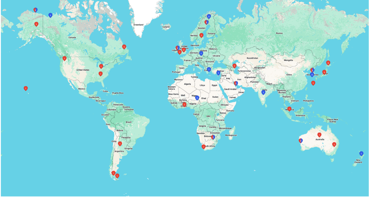
| Table 11-16: Mission Operations and Scheduling Software | ||
|---|---|---|
| Product | Manufacturer | Type of Product |
| COSMOS | OpenC3 | Open-source command and control system that can be used in all phases of testing and operations |
| Galaxy | The Hammers Company | Command and telemetry system that has been available since 2000 |
| Mercury | The Hammers Company | Automation for the flow of data files through a mission operations center or other facilities |
| Stars | The Hammers Company | Cloud compatible, spacecraft fleet trending and data access system |
| Secryt | The Hammers Company | Software uplink command encryption, telemetry decryption |
| tACT | The Hammers Company | Web-Based Team Activity Scheduling System |
| Auria Family of Products | Auria | Group of mission planning and scheduling products for both aerial and satellite imaging applications |
| Yamcs | Space Applications Services | Open-source command and control system |
| ACE Premier Family of Products | Braxton Technologies | Group of hardware and software components for end-to-end Satellite Operations Center (SOC) |
| Mission Control Software | Bright Ascension | Monitoring and control interface with “lights- out” automation features built-in |
| Major Tom | Xplore | Cloud-based command and telemetry system that can interface with some COTS flight software |
OpenC3 COSMOS
OpenC3 COSMOS is a free, open-source, open-architecture, command, control and communications system providing commanding, scripting, and data visualization capabilities for embedded systems and systems of systems. COSMOS is now a fully containerized, microservice-based architecture with a web-based frontend. COSMOS is intended for use during all phases of testing (board, box, and integrated system) and during operations. OpenC3 COSMOS is made up of a set of applications that can be grouped into four categories: real-time commanding and scripting; telemetry visualization; offline analysis; and utilities. Figure 11.29 shows how data flows through the microservices and is made available to users through an API and from a web-based interface. Any embedded system that provides a communication interface can be connected to COSMOS. All real-time communications of both commands and telemetry are logged in a cloud-native data store, which can use local hardware, or cloud-based storage for potentially infinite storage.
Additionally, program-specific tools can be written using the open-source OpenC3 COSMOS libraries, and these tools can interact with the commands and telemetry of all targets connected to the system. A paid enterprise edition of COSMOS is also available that adds important scaling and security features including: user accounts, Role-Based Access Control (RBAC), Kubernetes support with Helm charts, calendar and automation capabilities, and a library of pre-built plugins for common devices and protocols like SCPI devices and CFDP.
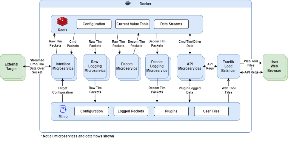
The Hammers Company
The Hammers Company offers a suite of ground data software and system solutions designed to support the entire spacecraft lifecycle; from instrument and/or component development, including flight software, through mission operations. Their commercial real-time command and telemetry system, Galaxy, has heritage on missions ranging from stratospheric balloons, CYGNSS (Cyclone Global Navigation Satellite System) and Landsat observation satellites in Earth orbit and Lunar Reconnaissance Orbiter (LRO). Galaxy is designed to handle spacecraft fleet operations by accepting telemetry from, and sending commands to, multiple spacecraft and ground stations simultaneously. See Table 11-14 for more Hammers Company ground data software and https://hammers.com/.
Major Tom
Xplore’s Major Tom® is a scalable, cloud-based mission control platform that provides satellite mission operations and planning tools for ground station scheduling, satellite tasking and telemetry monitoring. It provides satellite operators the ability to integrate and control ground segment applications and services, and further de-risks mission operations with features such as built-in ground network integrations, advanced analytics, interactive dashboards, and a customizable commanding API. Major Tom’s gateway API architecture, definitions, and protocols can integrate with custom ground station providers. This software is compatible with a heterogenous network of ground station providers and supports both constellation and individual mission operations with flexibility in satellite communication and commanding. New ground station network locations and providers can be added and it works with a unified data model for constant functionality across the entire network. Figure 11.30 provides a screenshot of the dashboard.
For more information, visit https://www.xplore.com/services/operations-as-a-service/major-tom.html.
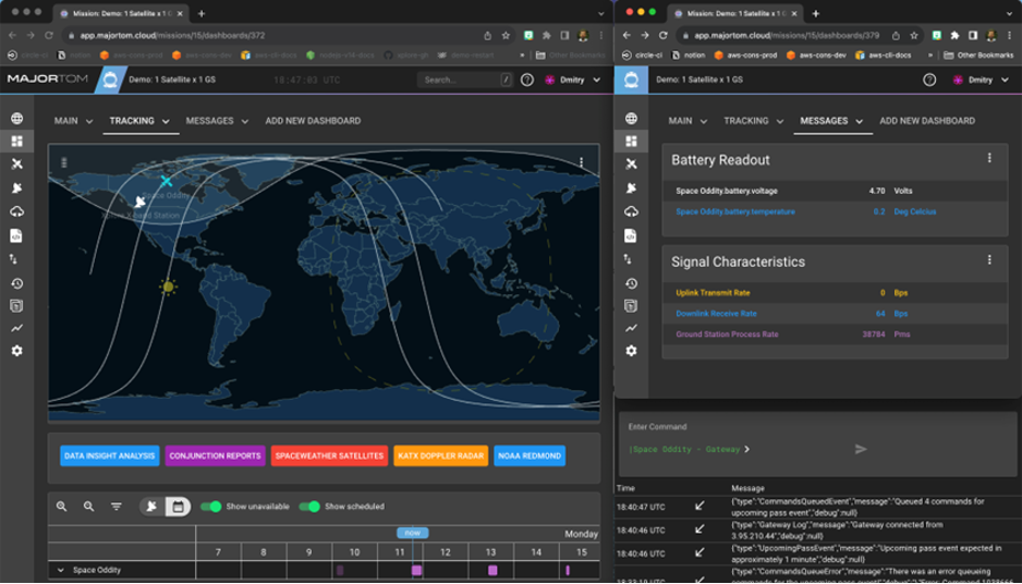
Auria Family of Products
Auria specializes in mission planning, scheduling, and space situational awareness software. The software suite consists of multiple applications that support analysis and operations for aerial and satellite imaging and space-to-ground networking. The mobile, web, desktop, and onboard scheduling applications have a variety of features, including: configurable systems, constraints, and goals; high-performance algorithms; deconflicted scheduling plans; visualizations and animations on the user interface, and flexible process flows and automation. Figure 11.31 shows Auria’s Collection Planning and Analysis Workstation (CPAW). For more information, visit https://www.auria.space/
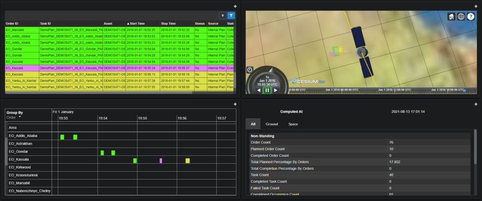
ACE CrtlPoint
The ACE CrtlPoint from Parsons (acquired Braxton Technologies in January 2021) is an automated space vehicle and ground station command and control (C2) application with a plug-in architecture that provides nearly “lights-out” TT&C operations. ACE CrtlPoint includes the hardware and software components necessary for a satellite MOC. Key applications include: integration with antenna scheduling; ground station control and status; data forwarding for analysis; command plan execution; anomaly detection; and a turnkey TT&C system. COTS capabilities plug into standardized environments, allowing the product to be ready for deployment immediately within a range of mission architectures. https://www.parsons.com/products/ace-ctrlpoint/
Bright Ascension HELIX
Bright Ascension rebuilt its original mission control software into a modern suite called HELIX, a highly integrated, end-to-end software platform for the entire mission lifecycle from flight software development, testing and simulation, to ground operations and end user insights and analytics. The HELIX suite includes the HELIX Groundkit, an advanced ground software development platform that assembles complete and bespoke ground software systems; HELIX Ops, the mission control environment designed to scale from single CubeSat missions to large multi-platform constellations; and HELIX Flightkit, a modular flight software development environment, designed to create mission-specific flight software using configurable and pre-validated components. Flightkit can reuse and adapt software packages developed for one mission for another mission with different platforms or subsystems. This flexibility allows teams to respond rapidly to changing requirements by easily swapping functional elements in and out of the system. Flightkit includes a library of pre-validated, ready-to-use components, along with the ability to develop custom modules to meet mission-specific functionality. Figure 11.32 is HELIX main screen. https://brightascension.com/helix/
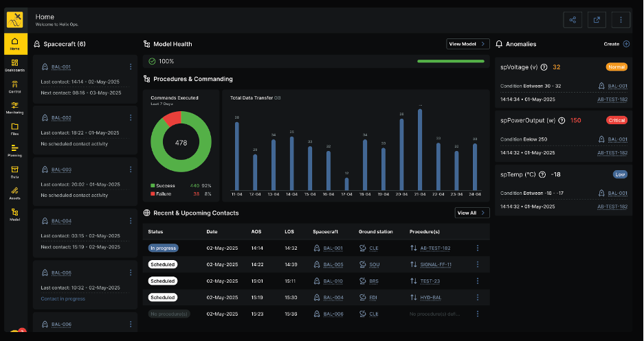
Yamcs Mission Control
Yamcs is a mission control software developed by Space Applications Services that is publicly available under the GNU Affero GPL license. It is designed for the command and control of the spacecraft, payload, ground station, and ground equipment, and supports telemetry reception, archiving, telecommand sending, alarm generation, and replay processing. Yamcs features a comprehensive web interface. The backend can be extended or customized using Java (though some plugins are only available to customers) and can be deployed in the cloud or on premises. The platform also supports industry standards like Consultative Committee for Space Data Systems (CCSDS), CCSDS File Delivery Protocol (CFDP), CubeSat Space Protocol (CSP), and XML Telemetric and Command Exchange (XTCE). The extensive API includes both REST and WebSocket. A desktop tool is available for authoring operator displays. Plugins for popular open-source visualization frameworks, such as Grafana and OpenMCT, are also available. A companion tool, the Yamcs Gateway, enables the development of Electrical Ground Support Equipment (EGSE) for spacecraft and payload development, supporting low-level interfaces like CAN bus, MIL-1553, SpaceWire and RS422. Figure 11.33 is a screenshot of the web GUI. In addition to the public AGPL releases, Space Applications Services offers commercial licenses and enterprise Support for Yamcs. For more information, see https://yamcs.org/.
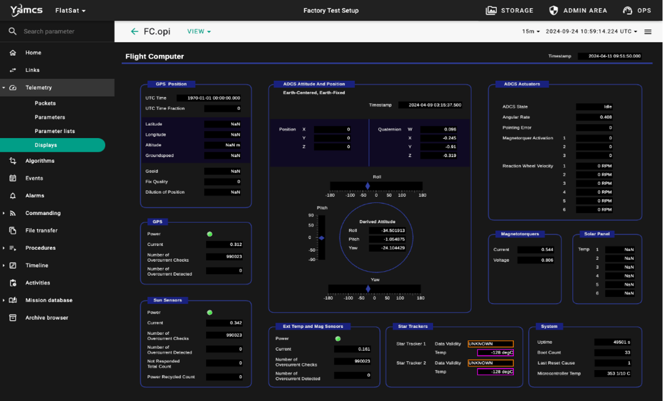
11.10 On the Horizon
Ground data systems must continue to evolve to keep up with the rapid pace of small satellite technology. Advancements in onboard processing and data storage will demand more capability in getting data to the ground. Mass production of small satellites is quickly becoming a reality and large constellations are now starting to be deployed to orbit. This will require ground system technology that can communicate with multiple satellites simultaneously. Free Space Optical communications and phased array ground systems are emerging solutions to these needs. While both technologies have seen years of investment, they are now just starting to be integrated into ground networks. While it may still be years before they become a staple for these networks, the following sections provide insight into the state of these technologies and where they are headed in the future.
11.10.1 Free Space Optical Communications
Increasing demand for data from NASA missions has led to a migration over the past few decades to increasingly higher RF bands (X, K, and Ka) and ultimately to the optical and near-infrared regimes. Free Space Optical (FSO) communications are expected to increase data rates by two orders of magnitude over traditional RF links (see the Communications chapter for more on FSO communications). The next generation systems will incorporate optical communications, and several early flight demonstrations and uses of optical communications in the coming decade are expected to be transformative for NASA and other space organizations. Whereas Ka-band frequencies go up to 40 GHz, the optical signal reaches up to 200,000 GHz. Higher frequencies have the potential for significant increases in data rates, theoretically proportional to frequency-squared if all other factors are equal. At optical wavelengths, other factors, such as atmospheric losses, receiver sensitivity, aperture, and power, must also be considered, but nonetheless, optical communications offer the potential for orders of magnitude improvement in data throughput.
For space applications, lasers are being used as the light source. Laser systems with dynamic systems such as fast-steering mirrors are used to accurately point the laser on the spacecraft to the ground terminal. Other methods using laser arrays for beam pointing are also being developed to reduce the need for complex dynamic pointing systems. Data is transmitted in the form of hundreds of millions of short pulses of laser light every second. The light is made of photons and the optical ground terminals are set up to collect the light at the photon level. In fact, the ground terminals are designed for an environment where relatively few photons may be received from the transmitter spacecraft, especially from deep space. Direct photon detection with Pulse Position Modulation (PPM) is used instead of the common RF technique of direct carrier coherent modulation to convey information. PPM modulation uses a time interval that is divided into several possible pulse locations, but only a single pulse is placed in one of the possible positions, determined by the information being transmitted. To detect extremely faint optical signals with relatively few photons through the atmosphere, optical ground stations can use a superconducting nanowire single-photon detector (SNSPD), which, to increase the sensitivity of the nanowires, uses a 1-Kelvin cryocooler. A real-time signal processing receiver uses time-stamped photon arrivals to synchronize, demodulate, decode, and de-interleave signals to extract information codewords. Hence, while the specific technologies employed differ in some respects from those used in radio frequency ground terminals, the higher-level functions performed by the optical communication ground terminal are similar.
Optical communication is attractive for mission designers using small, resource-constrained spacecraft because it offers a path to relatively high data rates with relatively small, low-power spacecraft equipment. The same volume and power savings can be experienced on the ground terminal side as well. This is driven by the size of the wavelengths involved. Because RF wavelengths are longer, the size of their transmission beam covers a wider area; therefore, the capture antennas for RF data transmissions must be very large. Laser wavelengths are orders of magnitude shorter, allowing data to be transmitted across narrower, tighter beams. This results in the ability to deliver the same amount of signal power to much smaller collecting areas. The reduction in antenna size applies for ground and space receivers, which allows for size and mass reductions on the spacecraft side.
NASA made great strides with its optical communication demonstration on the Lunar Atmosphere and Dust Environment Explorer (LADEE) mission. The pivotal NASA Lunar Laser Communications Demonstration (LLCD) was able to achieve 622 Mbps from lunar distance. NASA has several ongoing and planned optical communications demonstrations, including O2O, Illuma-T, T-Bird, and the Laser Communications Relay Demonstration (LCRD). LCRD is supported by Optical Ground Station (OGS)-1 at OCTL, and OGS-2 in Hawaii (51).
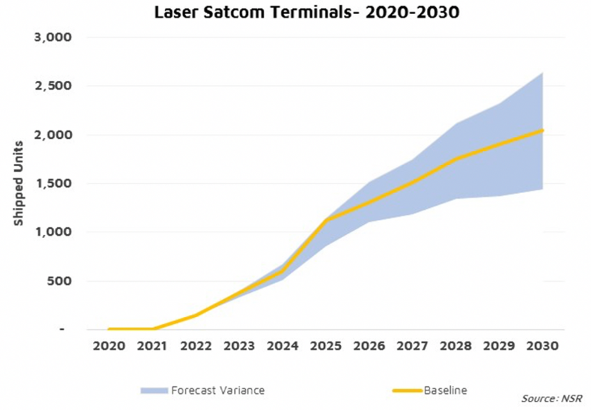
Northern Sky Research (NSR) predicts growth for optical communications, which needs to be matched by OGS (Figure 11.34). “The demand now is not for just one gigabit per second, not 10 gigabits per second, but tens if not hundreds of gigabits per second. And it’s growing exponentially. The only way to achieve that is by starting to use optical communications or laser communications to augment or to complement RF communications” (Barry Matsumori, CEO of BridgeComm, 2022) (22).
11.10.2 Optical Ground Stations and Future Infrastructure Requirements
OGS contain notably different equipment than RF stations, including an optics assembly, photon counter assembly (usually involving a photon-counting nanowire detector and cryostat), and signal processing assembly with a time-to-digital converter. Since optical communications use a frequency higher than RF (e.g., 1,550 nm downlink and 1,065 nm uplink wavelengths), the optical dishes can be smaller than RF antennas. To receive optical signals from a low-Earth orbit, 40–60 cm telescopes are sufficient. For successful deep space optical communications, calculations show that 3 m, 4 m, or even 8 m diameter ground apertures are required, depending on the distance from Earth. For these size apertures, when a 3–8 m OGS is not available, partnerships can be formed with large astronomy telescopes. For example, JPL-designed OGS equipment has been integrated at the Palomar Observatory (Hale 5-m telescope) for future use by the Deep Space Optical Communications (DSOC) demonstration. Note that OGS for LEO and deep space require different types of modems. It is also important for OGS to have spatial diversity. Weather, atmospheric conditions, turbulence, and aerosols in the air can degrade laser propagation. Because certain types and depth of cloud covers can cause signal loss, probability of link success increases with multiple diverse locations.
For interoperability between SmallSats and public and private optical ground stations, a common communications standard is key. The Consultative Committee for Space Data Systems (CCSDS) and Space Development Agency (SDA) provide recommendations for communications standards, including optical communications. Adhering to these standards by both SmallSats and ground stations allows for multi-mission optical ground stations.
JPL is operating the Optical Communications Telescope Laboratory (OCTL) at Table Mountain, CA, with a 1 m telescope, as shown in Figure 11.35 This dish was used for the LADEE mission and offered strong performance from a lunar distance (21). Most notably, JPL operates the DSN, supporting two-way RF communications and ranging services. Given the existing infrastructure, it is advantageous to augment a DSN RF antenna by installing optical segments at its center, making it a dual-purpose, RF-optical hybrid antenna. The installation is being implemented in two phases.
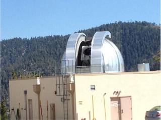
In 2022 a small prototype RF-Optical system, including the mirror, cameras, and backend has been installed at DSS-13 (Figure 11.36) at the Goldstone Deep Space Communications Complex. DSS-13 is the R&D 34 m BWG antenna at Goldstone. The combination of seven small (0.5 m) mirrors comprises a synthesized prototype optical aperture of about 1.3 m diameter. Since late 2023, DSS-13 has been continuously performing active laser downlinks. Control was verified to maintain segment position to <1 microradian, with first light successfully received from natural light sources. 1550 nm light was measured through the 100-meter fiber at the pedestal. JPL was able to track multiple sources across the sky from 20-80 degrees elevation.
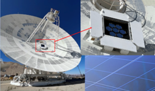
A JPL designed communications detector and optical receiver have been installed and tested over the air on DSS-13 as well.
The operational RF-Optical hybrid will ultimately include 64 mirrors each of 1 m diameter, installed as a segmented 8 m optical receive aperture/mirror physically inside one of the new DSN 34 m radio frequency ground terminals (DSS-23, in California). The final phase includes completion of the full 64- segment aperture on DSS-23, as illustrated in Figure 11.37, including a full year of field tests. This 8 m equivalent optical ground aperture will be operational in the early 2030s.
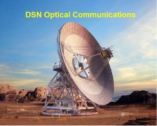
DSS-23 will be capable of a full set of RF services with the 34 m antenna in addition to high-rate optical communications with its 8 m optical assembly. Before the full operational readiness dates for optical communications, the 1.3 m partial optical systems will be usable at various times for best effort demonstration optical communications passes in the near-Earth or lunar regimes, as well as for deep space missions.
The DSS-23 optical receiver is the same design that JPL is delivering to the Palomar Observatory for use with the DSOC optical communications technology demonstration on the NASA Psyche mission. This receiver is also installed in ground terminals at White Sands and other locations for near- and deep-space missions, as well as Artemis. One exciting implication of this 8m equivalent optical aperture is that it meets the 230 Mbps downlink data rate requirement for human exploration of Mars.
Looking at the broader optical communications landscape, over the past decade the community has been confronted with a chicken-and-egg problem: due to the lack of a ground segment, the FSO space segment has been slow to develop, and additional investments have not been made due to the low number of satellites flying an FSO ground segment.
Europe
The European Optical Nucleus Network was formed between ESA ESOC, the Germany Aerospace Centre (DLR), Global Security Operations Center (GSOC), and KSAT. Parties agreed to have an interoperable, multi-mission approach based on the Consultative Committee for Space Data Systems (CCSDS) standards. Starting locations and characteristics are summarized in Table 11-17. The Nemea OGS (Figure 11.38) has been operational since 2022 after initial investments in the first commercial OGS, with the other stations expected to follow. The goal is to bring all building blocks together into an automated, cost-efficient, operational, multi-mission optical ground station service. This OGS uses modified COTS components to reduce cost and could also serve as a blueprint for future stations. KSAT co-located its first OGS with KSAT RF antennas in the mid-latitudes at Nemea, due to the temperate, weather, and the ability to shae existing infrastructure. The OGS is compliant with the Optical On-Off Keying (CCSDS 141b1) draft standard and is designed to be cost competitive to the KSATLITE service that KSAT is currently offering in the RF domain. The telescope is mounted more than 3 m above the ground to avoid ground layer turbulence. The dome is a one-part, completely retractable structure with UV-resistant plastic fabric. It is not connected to the telescope foundation to avoid coupling of vibrations caused by wind to the telescope system.
- KSAT co-located its first OGS with KSAT RF antennas in the mid-latitudes at Nemea, due to the temperate weather and sharing the existing infrastructure,
- The OGS is compliant with the Optical On-Off Keying (CCSDS 141b1) draft standard and is designed to become cost competitive with the KSATLITE service, which KSAT currently offers in the RF domain.
- The goal was to bring all building blocks together into an automated, cost-efficient, operational, multi-mission optical ground station service.
- For cost reduction modified COTS components have been selected.
- The telescope is mounted more than three meters above the ground to avoid ground layer turbulence.
- The dome is a one-part completely retractable structure with UV resistant plastic fabric. It is not connected to the telescope foundation to avoid coupling of vibrations caused by wind to the telescope system.
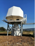
The First Data Link Between Commercial Optical Terminals has been validated through a temporary Sony optical terminal placed on the ISS, with a channel data-rate of 150 Mbit/s
with BER varying from 1e3 and <1e-6.
Table 11-17: European Optical Nucleus Network OGS Key Parameters
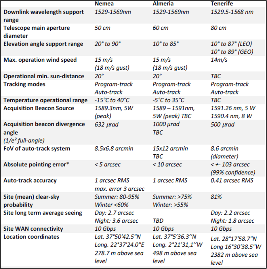
Japan
The National Institute of Information and Communications Technology (NICT) optical ground station in Japan also received transmissions from the SOLISS system by Sony CSL installed on the Kibo’s exposed facility on the ISS (25). In 2021, NICT also reported that the 1 m optical ground station in Koganei, Tokyo received via optical communication images taken by the satellite’s camera using the SOTA optical communications device mounted on a 50 kg-class microsatellite.
Germany
The DLR German Aerospace Center is another organization active in optical communications. About 25 km west of Munich, Germany, is their Optical Ground Station Oberpfaffenhofen (OGS-OP) that houses a 40 cm Cassegrain telescope (26). The German Aerospace Center has also developed a transportable optical ground station (TOGS). It has a 60 cm deployable telescope in a Ritchey- Chretien-Cassegrain configuration with a focal ratio of f/2.5. The telescope is supported by an alt-azimuth mount on a structure with four adjustable legs for leveling the mount and compensating for rough terrain. It has been successfully used to track the OPALS instrument on the ISS and serves as the primary ground station for the OSIRIS payload on the BiROS satellite. The German Aerospace Center OGS-OP and TOGS are shown in Figure 11.39.
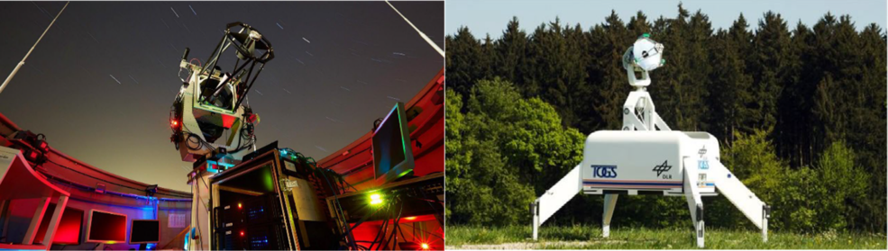
WORK Microwave is a system integrator and provides satellite communication technologies, including turnkey OGS tailored to mission requirements. In collaboration with KSAT and Astelco Systems, WORK Microwave contributed to the establishment of the first commercial ground station for ESA at Nemea, Greece, which became operational in 2021 (25). This station, designed with a half-meter aperture telescope from Astelco and a baseband modem developed by WORK Microwave, supports data rates up to 3 Gbps and was validated through tracking of sun-illuminated spacecraft. Separately, WORK Microwave developed a fully SDA Tranche 1 and 2 compliant Digital Optical Ground (DOG) suite that enables system configuration, monitoring, and control, and communication (30). This includes the DOG-M1 multi-mission modem, DOG-DA optical detector, DOG-CA electro-optical converter, and DOG-A1 amplifiers. The DOG suite supports bi-directional optical communication at rates up to 10 Gbps and is compatible with both SDA and CCSDS standards. While the Nemea station incorporates components from WORK Microwave, the fully SDA-compliant DOG suite represents a more recent and comprehensive system architecture, intended for broader deployment across LEO, MEO, GEO, and deep space missions. Figure 11.40 shows the OGS DOG schematics, with telescope control from WORK Microwave’s partners. More info on https://work-microwave.com/digital-optical-groundstation/.

Australia – New Zealand
The Australian Optical Ground Station Network (AOGSN) will eventually be made up of four ground stations in Western Australia, South Australia, the Australian National University (Australian Capital Territory), and New Zealand. The plan is to tie these stations together to produce a communication network that can support optical, RF, and future quantum communications. In spring 2021, Thales Australia signed a research extension with the SmartSat Cooperative Centre (CRC) for the development of advanced optical communications technologies (27).
Sascha Schediwy, head of the research group responsible for designing and building the WA Optical Ground Station (Figure 11.41), believes lasers will play a crucial role in future human missions to the Moon. “It’s likely to be how we’ll see high-definition footage of the first woman to walk on the Moon,” Dr. Schediwy said (abc.net.au).
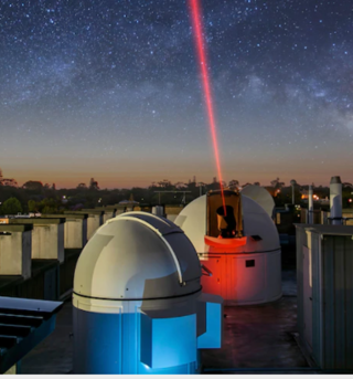
United States
In the U.S., The Aerospace Corporation is a player in the optical communication arena. Their manned OGS 40 cm telescope, located in El Segundo, CA, demonstrated 200 Mbps from 725 km. It is operating at a 1,064 nm wavelength; thus, it is not compatible with other optical ground stations or most COTS optical space terminals.
11.10.3 Techniques to Improve Optical Comm Reliability
Laser communication is essential for future telecom networks to supplement RF communications and enable:
- Very high throughput links (> 10 Gb/s and up to Tb/s)
- Communication without frequency band limitation
- Highly secure, stealthy, and non-interceptable links
It is essential for operational use cases:
- Multispectral observation of Earth from space (very bandwidth intensive)
- Securing sovereign communication
- Telecommunication constellations that rely on very broad bandwidth links
Cailabs
Cailabs develops, manufactures, and delivers turnkey Optical Ground Stations for laser communication, enabling high-speed satellite-to-ground links. With its standard TILBA-OGS-L10 design, Cailabs provides secure, robust, and spectrum-license-free bidirectional connections exceeding 10 Gbps for LEO-to-ground communications. TILBA-OGS integrates several key building blocks, based on proprietary Multi-Plane Light Conversion (MPLC) technology: TILBA-ATMO (downlink injection into a single mode fiber), TILBA-IBC (uplink incoherent beam combining), and TILBA-CBC (coherent beam combining). These sub-systems enable TILBA-OGS to effectively mitigate atmospheric turbulence on both the receiver (Rx) and transmitter (Tx) sides of the link without the hassles and complexity of adaptive optics or co-aligned multiple apertures. This turbulence-mitigation technology ensures scalability to meet future terabit-per-second (Tbps) feeder link requirements and beyond.
Using TILBA-OGS-L10, Cailabs has performed successful space-to-ground laser communications with several spacecraft constellations. In 2025, Cailabs announced robust and repeatable bidirectional communication links with Kepler Pathfinder following SDA OCT standard v3.0.1, demonstrating the first commercial realization of SDA-compliant satellite-to-ground optical communications. TILBA-OGS is fully compatible with CCSDS and SDA standards (all tranches) and supports integration with a wide range of ground modems.
As of October 2025, TILBA-OGS is installed in France (operated by Cailabs) and in Western Australia (operated by Swedish Space Corporation), with 10+ additional units under production for governmental and commercial OGS programs. Cailabs is ready to meet the growing market demand with its new assembly and validation platform, capable of building up to five TILBA-OGS units in parallel. Following its recent $67 million fundraising, Cailabs is scaling its production capacity to 50 Optical Ground Stations per year by 2027, paving the way for the rapid deployment of a global optical ground station network (28). (https://www.cailabs.com/en/)
11.10.4 Role of Optical Relays
Optical inter-satellite links are “critical to the success of the Space Development Agency’s low Earth orbit constellation” known as the Transport Layer. SDA-Funded laser terminal technology could connect to multiple satellites simultaneously. Each satellite in the Pentagon’s “planned mesh network of communications satellites could have as many as many as four laser links so they can talk to other satellites, airplanes, ships, and ground stations.” BridgeComm, which recently received an SDA contract, “developed a so-called ‘one-to-many’ optical communications technology for point-to-multipoint transmissions” which could “help reduce the cost of building constellations by requiring fewer terminals,” Michael Abad-Santos, senior vice president of business development and strategy at BridgeComm] said. BridgeComm first demonstrated “point to multipoint optical communications in 2019 in a project with Boeing, and has since continued to mature the technology,” Abad-Santos said (29).
Warpspace is a private Japanese company developing an inter-satellite communication system based on laser communication (Figure 11.43). The WarpHub InterSat link relays will enable low latency data delivery from MEO, and in the future they will connect to the Lunar Gateway or planetary deep space via optical communications (see https://warpspace.jp/).
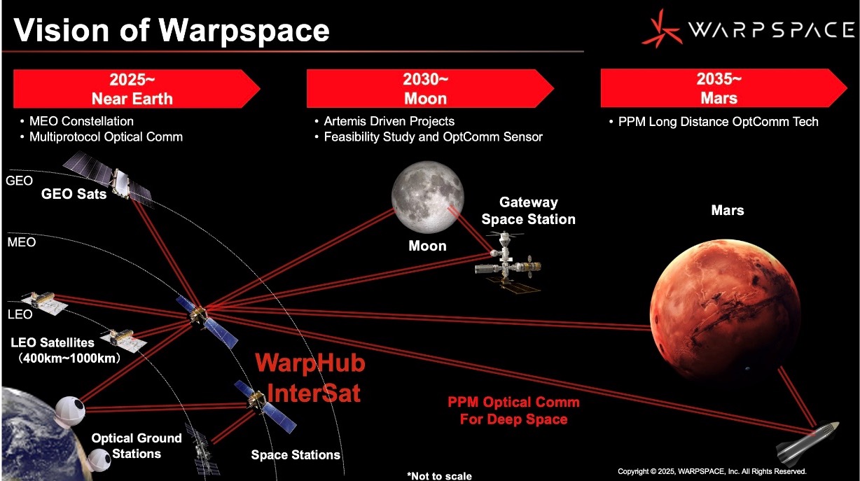
11.11 Summary
The ground segment serves as the gateway to getting valuable data collected by the satellite into the hands of the user. It is a critical component of the satellite system that requires attention at the earliest stages of mission planning. Understanding what ground solution best meets the needs of the mission has a direct impact on the spacecraft design, concept of operations, launch schedule, mission operations cost, and expected data volume for processing. Much effort also goes into preparing for the interaction between the satellite and ground network. Developing software and simulations, drafting operations manuals, conducting operations rehearsals, and performing compatibility tests are all part of standard practice. Post- launch, the ground station also plays a key role in locating and commissioning the spacecraft.
In looking forward to the future of ground systems, the clear objective is how to bring the data down more efficiently. Great strides are being made with optical communications where it is possible to have increases in data per pass that are orders of magnitude above what can be achieved with RF communications. Optical communication technology is now being infused into ground system architectures, and flight hardware is becoming miniaturized enough to fit within small satellites. The ability of these systems to quickly change beam directions and acquire multiple targets will be critical for communicating with constellations of small satellites.
While the tried-and-true RF ground system solution remains the workhorse for small satellites, the innovative nature of the small satellite platform will soon challenge the community to adapt to systems capable of handling hundreds of satellites and high data volumes. Efforts are ongoing to keep pace, but only time will tell whether ground systems will continue to advance or potentially impede the small satellite revolution.
For feedback solicitation, please e-mail: arc-sst-soa@mail.nasa.gov. Please include a valid business e-mail so someone may contact you further.
References
- K. Schauer, “NASA to Commercialize Near-Earth Communications Services.” October 26, 2020. [Online] Available at: https://www.nasa.gov/feature/Goddard/2020/nasa-to-commercialize-near-earth-communications-services
- National Aeronautics and Space Administration, “Space Communications and Navigation.” [Online] 2021 Available at: https://www.nasa.gov/directorates/heo/scan/services/networks/near_space_network
- Uppal, Rajesh. “Satellite Ground Segment as a Service (GSaaS) driven by New Space requirements.” [Online] Available at: https://idstch.com/space/satellite-ground-segment-as-a-service-gsaas-driven-by-new-space-requirements/
- Nguyen, Louis. “Ground Stations as a Service (GSaaS) for Near Real-time Direct Broadcast Earth Science Satellite Data.” [Online] Available at: https://esto.nasa.gov/forums/estf2021/Presentations/June10/Nguyen_GSON_ESTF2021.pdf
- R. O’Dwyer. “Iridium 88kbps service commercially available.” November 11, 2021. [Online] Available at: https://smartmaritimenetwork.com/2021/11/11/iridium-88kbps-service-commercially-available/
- D. Werner. “Analytical Space wins $26.4 million to establish optical network.” February 10, 2021. [Online] Available at: https://spacenews.com/analytical-space-wins-26-4-million-to-establish-optical-network/
- Celestia ST, “TNO and Celestia STS sign agreement to commercialize Optical Modem.” June 30, 2021. [Online] Available at: https://celestia-sts.com/2021/tno- and-celestia-sts-sign-agreement-to-commercialise-optical-modem/
- DeWitt, Henry. Satellite Ground Station Control. DeWitt & Associates. Accessed: July 2022. [Online] Available at: http://www.dewitt-assoc.com/groundStation.html
- National Aeronautics and Space Administration, “Space System Protection Standard” NASA-STD-1006A. July 15, 2022. [Online] Available at: https://standards.nasa.gov/sites/default/files/standards/NASA/A/0/2022-07-15-NASA-STD-1006A-Approved.pdf
- National Institute of Standards and Technology, “Security Requirements for Cryptographic Modules,” FIPS PUB 140-3, March 22, 2019. [Online] Available at: https://doi.org/10.6028/NIST.FIPS.140-3
- National Institute of Standards and Technology, “Engineering Trustworthy Secure Systems,” November 2022, [Online] Available at: https://doi.org/10.6028/NIST.SP.800-160v1r1
- Consultative Committee for Space Data Systems, “Application of Security to CCSDS Protocols,” Informational Report, Issue 3, March 2019, [Online] Available at: https://ccsds.org/Pubs/350x0g3.pdf
- Consultative Committee for Space Data Systems, “Security Guide for Mission Planners,” Informational Report, Issue 2, April 2019, [Online] Available at: https://ccsds.org/Pubs/350x7g2.pdf
- Cybersecurity and Infrastructure Security Agency, Space Policy Directive 5, Cybersecurity Principles for Space Systems, September 04, 2020, [Online] Available at: https://www.cisa.gov/resources-tools/resources/space-policy-directive-5
- National Aeronautics and Space Administration, “NASA’s Commercial Communications Services.” [Online] Available at: https://www.nasa.gov/directorates/heo/scan/services/nasas_commercial_communications_services
- R. Ross, V. Pillitteri, R. Graubart, D. Bodeau, R. McQuaid, “Developing Cyber Resilient Systems: A Systems Security Engineering Approach.” SP 800-160 Vol. 2. November 2019.
- R. Ross, M. McEvilley, J. Oren, “Systems Security Engineering: Considerations for a Multidisciplinary Approach in the Engineering of Trustworthy Secure Systems.” NIST SP 800-160 Vol. 1, November 2016 (Updated March 21, 2018), [Online] Available at: https://csrc.nist.gov/publications/detail/sp/800-160/vol-1/final
- R. Jewett, “Viasat Releases New Large-Aperture Space-to-Ground Communication Antennas,” ViaSatellite, January 20, 2022. [Online] Available at: https://www.satellitetoday.com/ground-systems/2022/01/20/viasat-releases-new-large-aperture-space-to-ground-communication-antennas/
- Sampathkumar, Arun Kumar. Uber-ization of Ground Stations. “The Small Satellite Market’s Enabling Aggregator Wave.” [Online] Available at: https://interactive.satellitetoday.com/via/august-2021/uber-ization-of-ground-stations-the-small-satellite-markets-enabling-aggregator-wave/
- IO Spacecom. “Launching Go.BIC at SmallSat Conference 2024.” Press Release. August 5, 2024. [Online] Available at: https://www.iq-spacecom.com/news/highlights/iq-spacecom-and-rbc-signals-launch-the-go-bic-service
- National Aeronautics and Space Administration, “LLCD: 2013-2014,” July 15, 2018 [Online] Available at: https://www.nasa.gov/directorates/heo/scan/opticalcommunications/llcd/
- Waterman, S. “Space Lasers Come of Age: Optical Communications for Satellites Are Ready for Prime Time.” February 22, 2022. [Online] Available at: https://interactive.satellitetoday.com/via/march-2022/space-lasers-come-of-age-optical-communications-for-satellites-are-ready-for-prime-time/_fragment.html
- National Aeronautics and Space Administration, “Lunar Laser Communication Demonstration: NASA’s First Space Laser Communication System Demonstration Fact Sheet.” [Online] Available at: https://www.nasa.gov/sites/default/files/llcdfactsheet.final_.web_.pdf
- Krynitz, Martin and Heese, Clemens and Knopp, Marcus Thomas and Schulz, Klaus-Jürgen and Henniger, Hennes, “The European Optical Nucleus Network,” 16th International Conference on Space Operations (SpaceOps 2021), 03.-05. May 2021.
- National Institute of Information and Communications Technology, “Small Optical Link for International Space Station (SOLISS) Succeeds in Bidirectional Laser Communication Between Space and Ground Station.” April 30, 2020. [Online] Available at: https://www.nict.go.jp/en/press/2020/04/30-1.html
- Florian Moll, Amita Shrestha, Christian Fuchs, “Ground Stations for Aeronautical and Space Laser Communications at German Aerospace Center.” Proc. SPIE 9647, Advanced Free-Space Optical Communication Techniques and Applications. https://core.ac.uk/reader/31021696
- Thales, “Beam me up! Thales & Goonhilly Earth Station Collaborate on Research into Laser Beams as Data Pipes.” June 8, 2021. [Online] Available at: https://www.thalesgroup.com/en/australia/press-release/beam-me-thales-goonhilly- earth-station-collaborate-research-laser-beams
- Swedish Space Corporation. “SSC awarded 2.26M€ for NODES.” Press Release. May 15, 2023. [Online] Available at: https://sscspace.com/ssc-awarded-2-26me-for-nodes/
- S. Erwin, “DoD Space Agency Funds Development of Laser Terminal that Connects to Multiple Satellites at Once.” March 10, 2022. [Online] Available at: https://spacenews.com/dod-space-agency-funds-development-of-laser-terminal-that-connects-to-multiple-satellite-at-once/
- “World´s 1st SDA T1 & T2 compliant digital optical ground station comms package,” March 6, 2024. Satnews. [Online] Available at: https://news.satnews.com/2024/03/06/worlds-1st-sda-t1-t2-compliant-digital-optical-ground-station-comms-package/