


![Request for Information – Potential [Placeholder for Prize]](https://assets.science.nasa.gov/dynamicimage/assets/science/psd/solar/2023/09/s/solarsystem_0.jpg?w=1024)

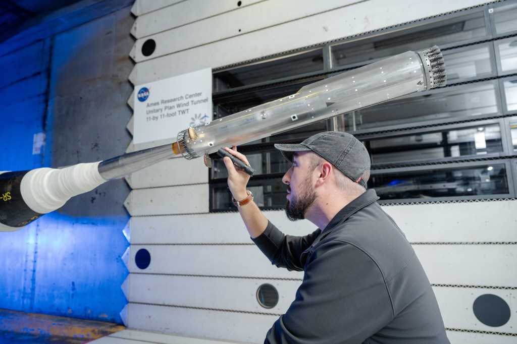


Unitary Plan Wind Tunnel 9-by 7-foot SWT Test Section
The 9-by 7-foot Supersonic Wind Tunnel (9×7 SWT) facility is part of the Unitary Plan Wind Tunnel (UPWT) complex at NASA’s Ames Research Center at Moffett Field, California, where generations of commercial and military aircraft and NASA space vehicles, including the space shuttle, have been designed and tested.
The 9×7 SWT is a closed-return, variable-density tunnel with an asymmetric, sliding-block nozzle. It is one of three separate test sections powered by a common drive system. Interchangeability of models among the UPWT test sections allows testing across a wide range of conditions. Airflow is generated by an 11-stage, axial-flow compressor powered by four variable-speed, wound-rotor induction motors.
The 9×7 SWT continues to provide aerodynamic data for NASA’s manned spaceflight efforts whose goal it is to create the rockets and spacecraft necessary to take explorers to Earth orbit, the Moon, and eventually, to Mars.
![]() ARC UPWT 9-by 7-foot Brochure.pdf
ARC UPWT 9-by 7-foot Brochure.pdf
Capability
- Mach Range= 1.55 to 2.55
- Rn= 0.50 to 5.7 million per foot
- Pt= 2.8 to 29.5 psia
- Maximum stagnation temperature = 600°R
- Closed circuit, single return, variable density, continuous flow wind tunnel
- Interchangeability of models between Unitary test sections allows testing across a wide range of conditions
- Internal strain-gage sting mount, model component balances are used for measuring forces and moments. Ames and Langley inventories typically available
- Full support of DTC PSI Module capability
- Fully automated control of tunnel conditions and simultaneously variable pitch and yaw positions
- Capability for measuring multiple fluctuating pressures
- There are two controllable 3000 psi auxiliary air systems capable of flow rates up to 40 lb/sec each. One line can be controlled up to 80°F and the other up to 400°F
- Full data system support capability included (Unix system with extra X-terminals available)
- Full internal and external network capability. PCs and Macs available to customers as needed
- Typical two weeks of model build up and instrument preparation is included in the facility occupancy charge
Operating Characteristics
- Mach number (continuously variable): 1.55 to 2.50
- Stagnation pressure 4.4 to 29.5 psia
- Reynolds number= 0.50 to 5.7 million per foot
- Maximum stagnation temperature 600°R
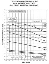
*View 9-by 7-foot Supersonic Wind Tunnel Operating Characteristics in a new window
![]() 9×7-ft Test Section Operating Characteristics.pdf
9×7-ft Test Section Operating Characteristics.pdf
Test Section Dimension
- Height: 7.0 ft.
- Width: 9.0 ft.
- Length: 18.0 ft.
- Access Hatches, Removable Ceiling Panel: 6.0 x 9.0 ft.
- Side doors: 3.0 x 6.5 ft.
- Total test section length = 18 ft. Effective (useable) Length = 11 ft.
Test Section Dimensions Plan View
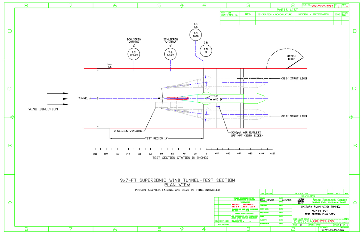
*View 9-by 7-foot Supersonic Wind Tunnel Test Section Plan View dimension drawing in a new window
![]() 9-by 7-foot Test Section Plan Drawing.pdf
9-by 7-foot Test Section Plan Drawing.pdf
Test Section Dimensions Side Elevation View
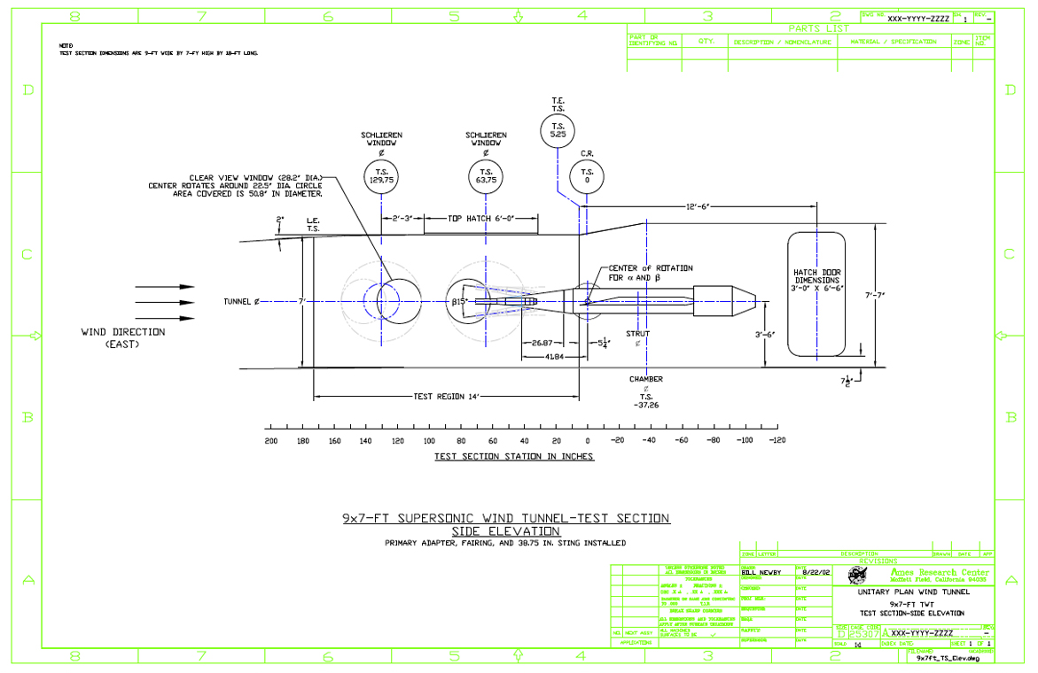
![]() 9-by 7-foot Test Section Side Elevation View Drawing.pdf
9-by 7-foot Test Section Side Elevation View Drawing.pdf
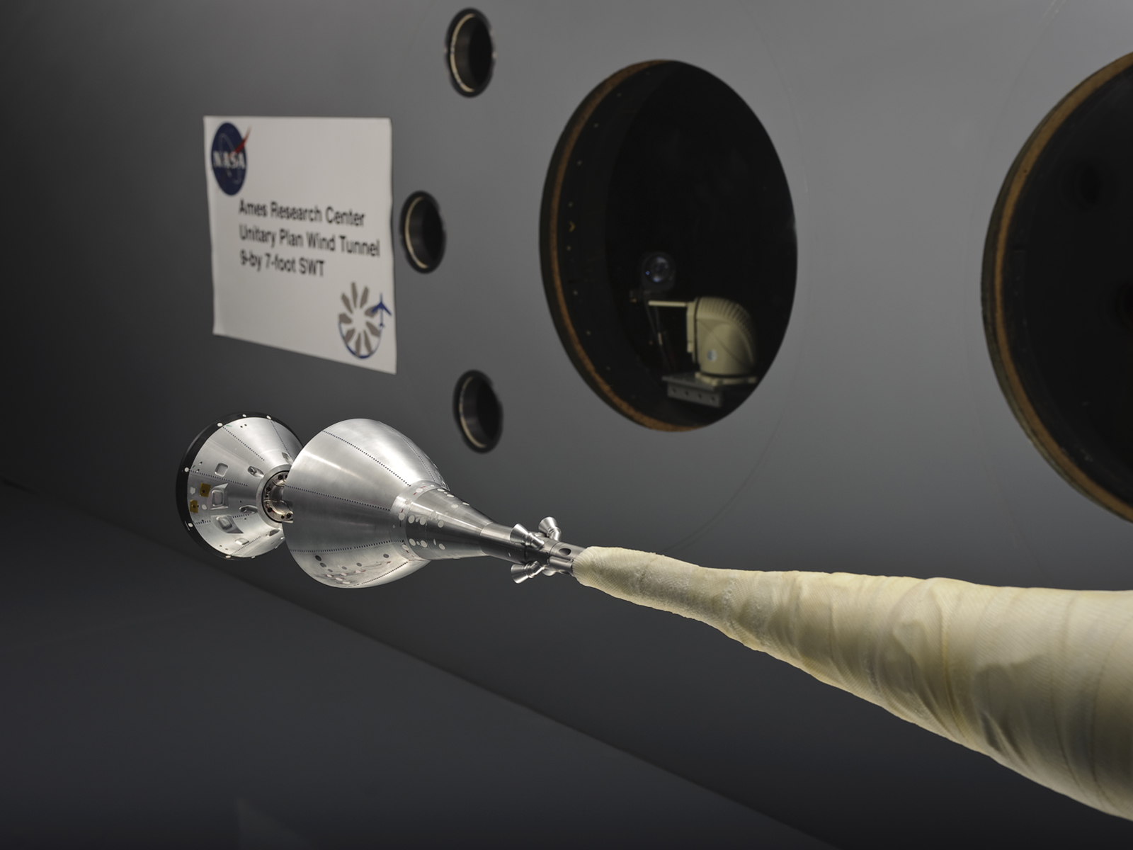
Model Installation Diagram
Model installation is normally accomplished through a 3×6.5 foot door in the north wall of the diffuser. Model/sting assemblies can quickly be brought into the test section via a removable ceiling track. Under special circumstances the model may be installed through the 6×9 foot ceiling panel. The model installation is presented in the image below.
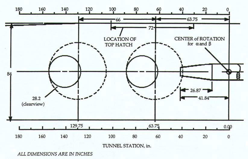
Model Support System
A traversing strut downstream of the test section can be programmed to translate horizontally to maintain a desired point of rotation throughout the horizontal-plane angle-range, generally angle-of-attack.
The center of rotation in the vertical plane is 5.3 inches aft of the strut leading edge. The horizontal and vertical plane angles are continuously variable and are determined by the relative positions of a knuckle and sleeve inside the support body. The model support system can position the model at attitudes circumscribed by a 15-degree half-angle cone.
Bent primary adapters of 5, 10, 12.5, and 20 degrees are available to alter the range of model angles.
Numerous stings of differing lengths and taper arrangements are also in inventory.
Forces and Moments
Forces and moments about the model support center of rotation in the tunnel axis are limited to:
- Vertical: ± 4,000 lbs
- Lateral: ± 8,000 lbs
- Axial: ± 3,000 lbs
- Rolling Moment: ± 104,000 in-lbs
- Combined Vertical and Lateral Bending Moment: ± 800,000 in-lbs
Flow Visualization
Flow visualization techniques such as Schlieren, Pressure Sensitive Paint, Oil Flow, Tufts, Sublimation, Skin Friction Interferometry, and Liquid Crystal can be obtained by appropriately positioning 2.35-foot diameter optical-quality windows in the test section sidewalls. Still and color video capability are provided.
High-Pressure Air
High-pressure air (3,000 psi) is available at weight flows up to a total of 80 pounds per second through dual, independently controlled digital valves. Air from one of these lines can be preheated using a one megawatt moveable heater.
Reflected Shock Waves
Shock waves reflecting on the model from the solid test section walls will have a detrimental effect on the model forces and pressures and must be avoided. When determining appropriate model size and attitude, calculate the shock rhombus by assuming reflections at the Mach angle from a 4-inch thick wall boundary layer.
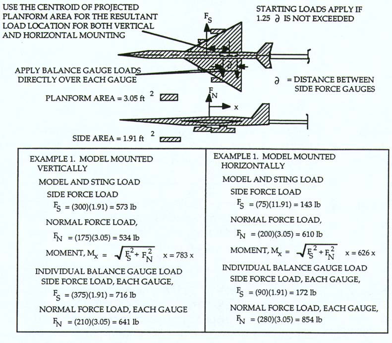
Starting Loads
The design of models to be tested in the 9-by 7-foot Supersonic Wind Tunnel must allow for additional critical conditions associated with blockage (the ratio of model-projected frontal area to test section cross-sectional area) and transient starting loads. Large model blockages provide a potential to “unstart” the airflow, allowing a strong shock wave to pass through the test section resulting in possible damage to the model, sting and balance. The ratio of model wing span to tunnel width for minimum supersonic performance verification interference should not significantly exceed 0.5. The maximum recommended ratio of model cross-sectional area to test section cross-sectional area is about 0.010 (model at 0° angle of attack).
Normal procedure is to reduce the tunnel pressure and position the model for minimum loads before beginning the acceleration to, or deceleration from, supersonic conditions.
However, significant transient loads are still generated by the swirling, subsonic, separated flows preceding the establishment of sonic velocity in the upstream throat. To ensure that a model, sting and balance will withstand these transients, they must be designed to withstand the empirically derived starting loads indicated in the table below.
Starting Loads Table
| Starting Loads | ||||
| Model Orientation | Model and Sting Loads, lb/ft2 Winged Models | Model and Sting Loads, lb/ft2 Body Alone | Individual Balance Gauge Loads lb/ft2 Winged Models | Individual Balance Gauge Loads, lb/ft2 Body Alone |
| Vertical Primary Lifting Surfaces: | ||||
| Side Force (Vertical Direction) | 300 | 200 | 375 | 200 |
| Normal Force (Horizontal Direction) | 175 | 150 | 210 | 150 |
| Horizontal Primary Lifting Surfaces: | ||||
| Side Force (Horizontal Direction) | 75 | 150 | 90 | 150 |
| Normal Force (Vertical Direction) | 200 | 200 | 280 | 200 |