


![Request for Information – Potential [Placeholder for Prize]](https://assets.science.nasa.gov/dynamicimage/assets/science/psd/solar/2023/09/s/solarsystem_0.jpg?w=1024)


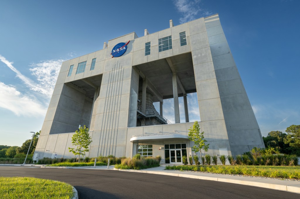


UPWT 11-by 11-foot TWT Test Section
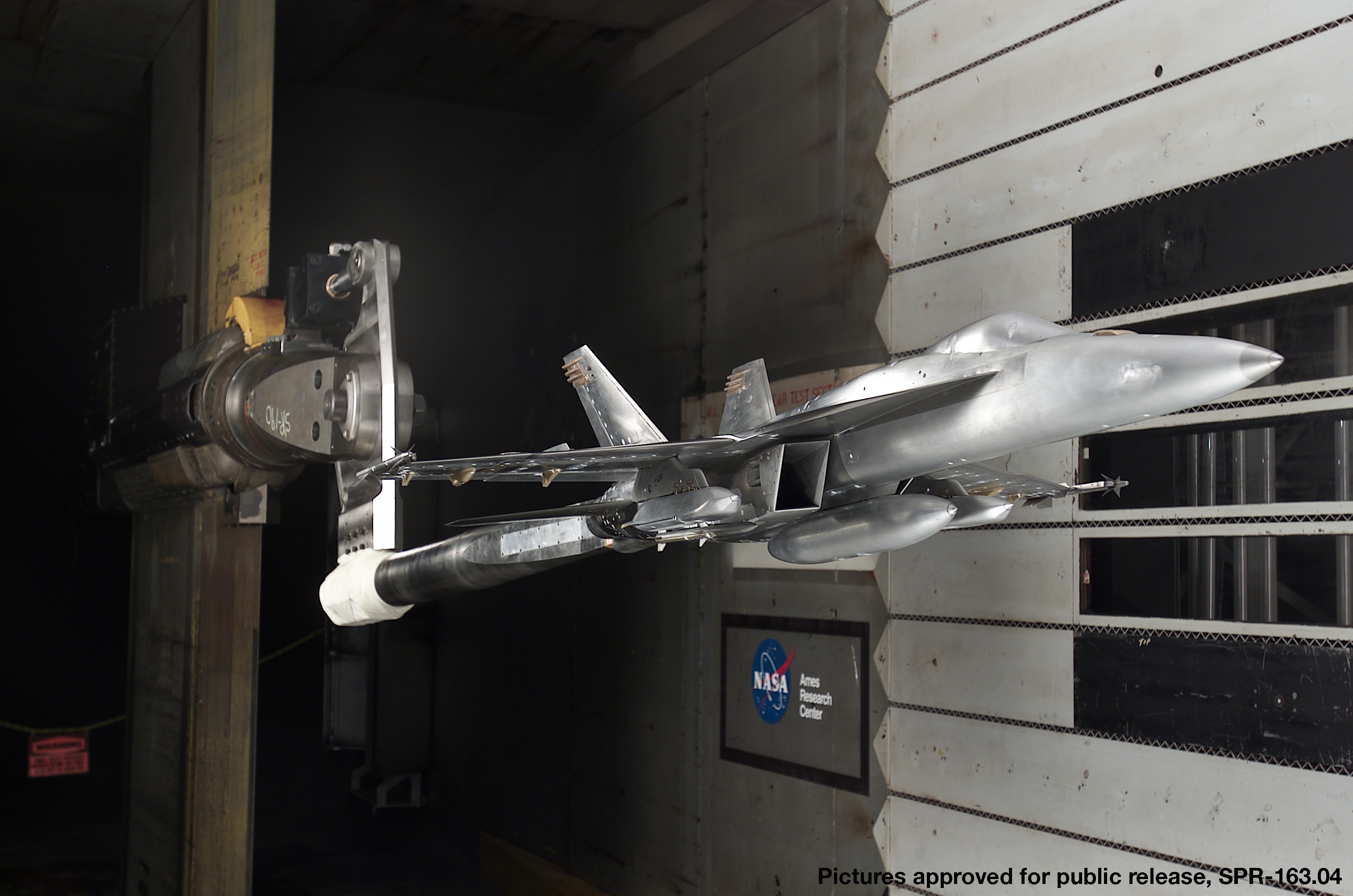
The 11-by 11-foot Transonic Wind Tunnel (11-foot TWT) Facility is part of the Unitary Plan Wind Tunnel (UPWT) complex at NASA’s Ames Research Center at Moffett Field, California, where generations of commercial and military aircraft and NASA space vehicles, including the space shuttle, have been designed and tested.
The 11-foot TWT is a closed-return, variable-density tunnel with a fixed-geometry, ventilated test section with a flexible wall nozzle. It is one of three separate test sections powered by a common drive system. A three-stage, axial-flow compressor powered by four wound-rotor, variable-speed induction motors, produces airflow. Interchangeability of models among the UPWT test sections allows testing across a wide range of conditions.
The 11-foot TWT has been instrumental in the development of virtually every domestically produced commercial transport and military fixed-wing airframe since the 1960s. The facility is used extensively for airframe testing and aerodynamic studies and has played a vital role in every manned space flight program.
![]() ARC UPWT 11-by 11-foot Brochure.pdf
ARC UPWT 11-by 11-foot Brochure.pdf
Capability
- Mach range = 0.20 to 1.40
- Rn = 0.30 to 9.6 million per foot
- Stagnation pressure = 3.0 to 32.0 psia
- Maximum stagnation temperature = 150°F. Typical temperature variation over the course of a test = 20°F
- Closed circuit, single return, variable density, continuous flow wind tunnel
- Interchangeability of models between Unitary Plan Wind Tunnel (UPWT) test sections allows testing across a wide range of conditions
- Internal strain-gage sting mount, model component and floor balances are used for measuring forces and moments. NASA Ames and NASA Langley inventories typically available
- Full support of DTC psi module capability
- Support strut has simultaneously variable pitch and yaw capability (± 15°)
- Two controllable 3000 psi auxiliary air systems capable of flow rates up to 40 lb/sec each. One line can be controlled up to 80°F and the other up to 400°F
- User interaction will be X-terminal based
- Full internal and external network capability. PCs and Macs available to customers as needed
- Typical two weeks of model build up and instrument preparation included in the facility occupancy charge
Operating Characteristics
- Mach number (continuously variable): 0.20 to 1.40
- Stagnation pressure: 3.0 to 32.0 psia
- Reynolds number= 0.30 to 9.6 million per foot
- Maximum stagnation temperature: 600°R
- Strut angle of attack: range nominally ± 15°
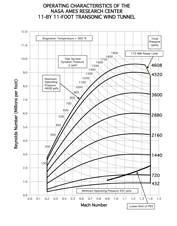
*View Operating Characteristics in a new window
![]() 11-ft Test Section Operating Characteristics.pdf
11-ft Test Section Operating Characteristics.pdf
Test Section Dimensions
- Height: 11.0 ft
- Width: 11.0 ft
- Length: 22.0 ft
- Access hatch, top: 7.0 x 22.0 ft
- Side doors: 3.0 x 4.9 ft
Test Section Dimensions Plan View
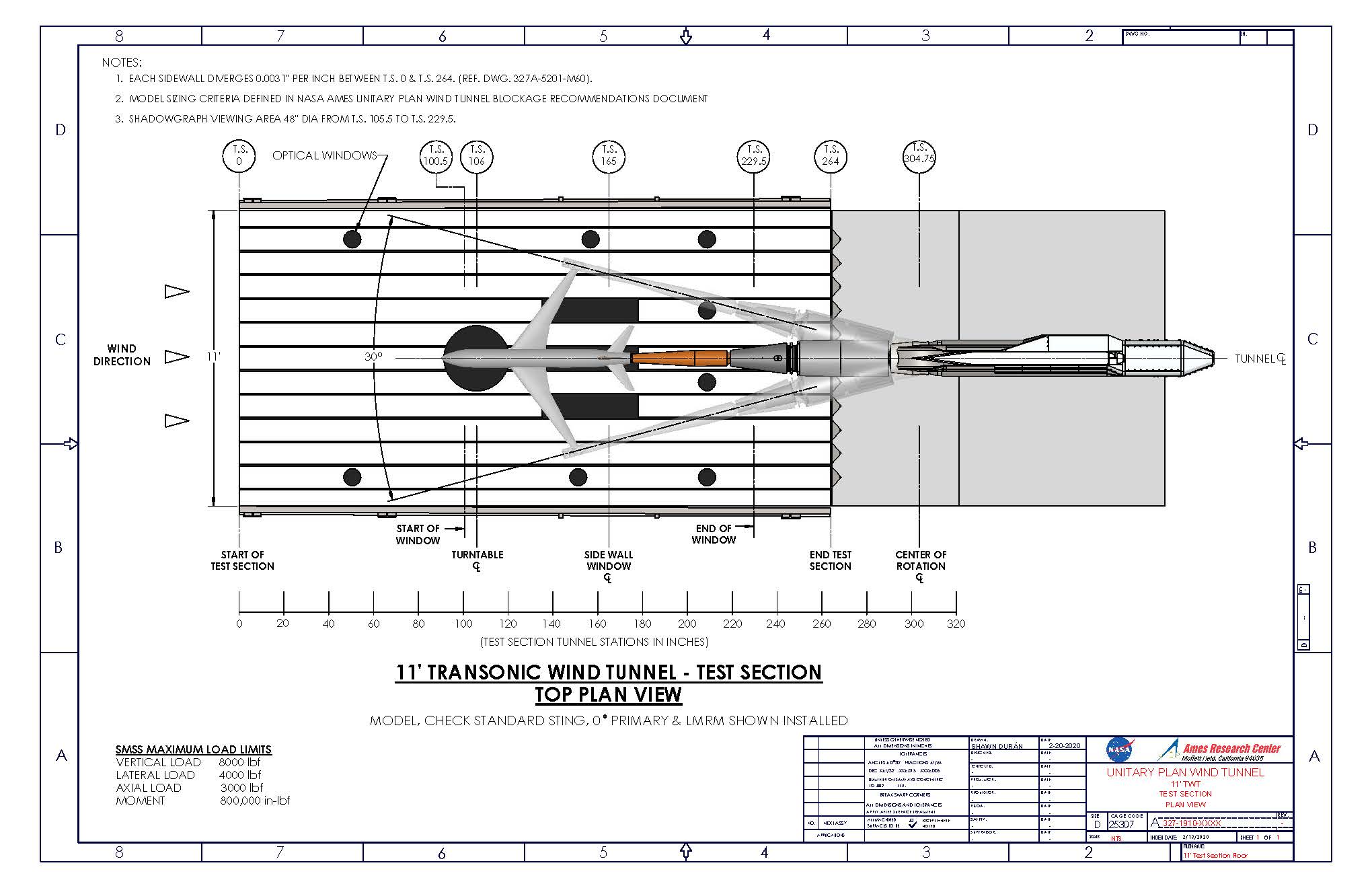
*View 11-ft Transonic Wind Tunnel Test Section Plan View dimensions drawing in a new window
![]() 11-ft Test Section Plan View Drawing.pdf
11-ft Test Section Plan View Drawing.pdf
**Notes 2: Model Sizing Criteria Defined in NASA Ames Unitary Plan Wind Tunnel Blockage Recommendations
Test Section Dimensions Side Elevation View
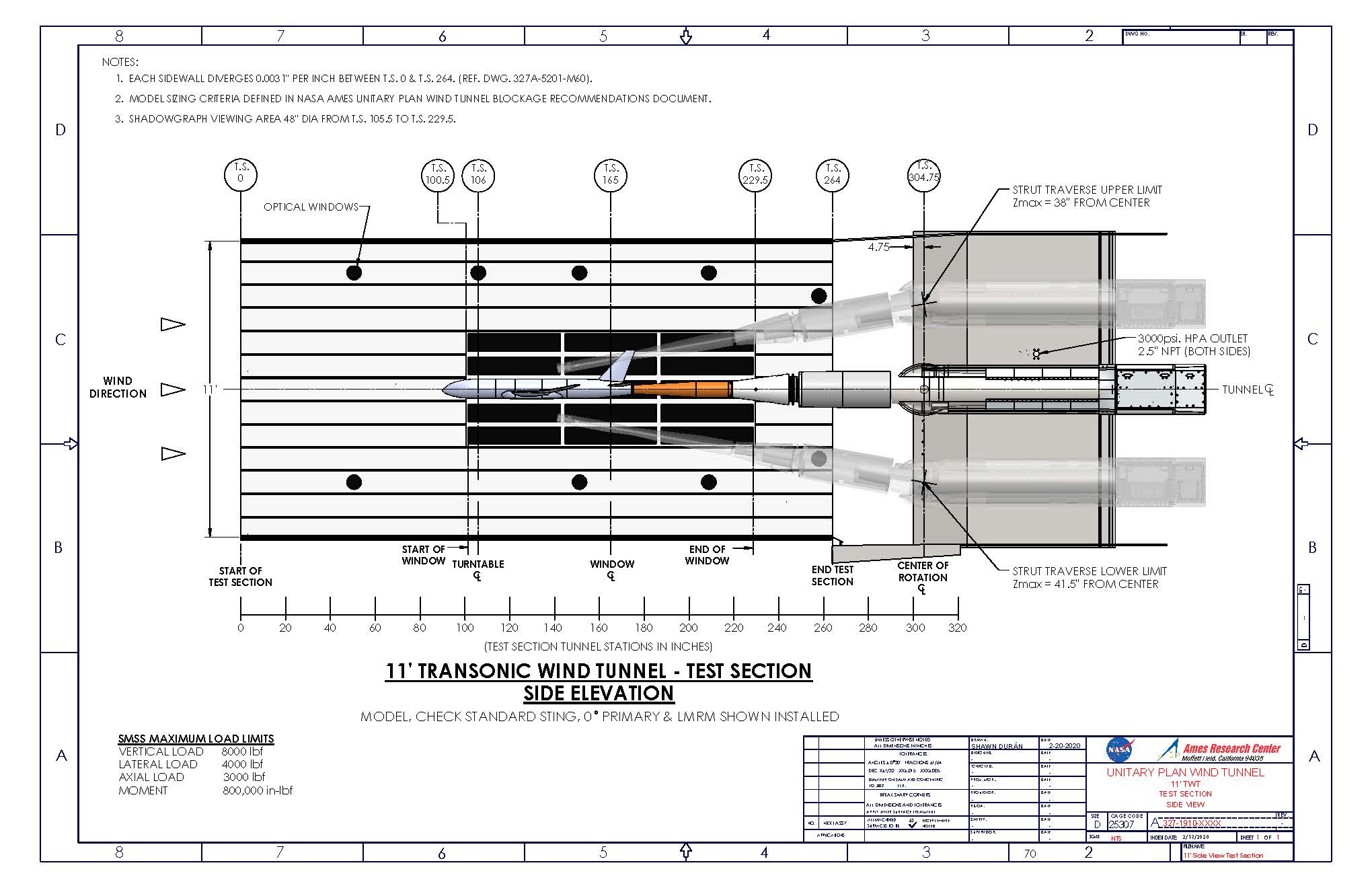
* View 11-ft Transonic Wind Tunnel Test Section Side Elevation View dimensions drawing a new window
![]() 11-ft Test Section Side Elevation View.pdf
11-ft Test Section Side Elevation View.pdf
**Notes 2: Model Sizing Criteria Defined in NASA Ames Unitary Plan Wind Tunnel Blockage Recommendations
Test Section Ceiling Plan View
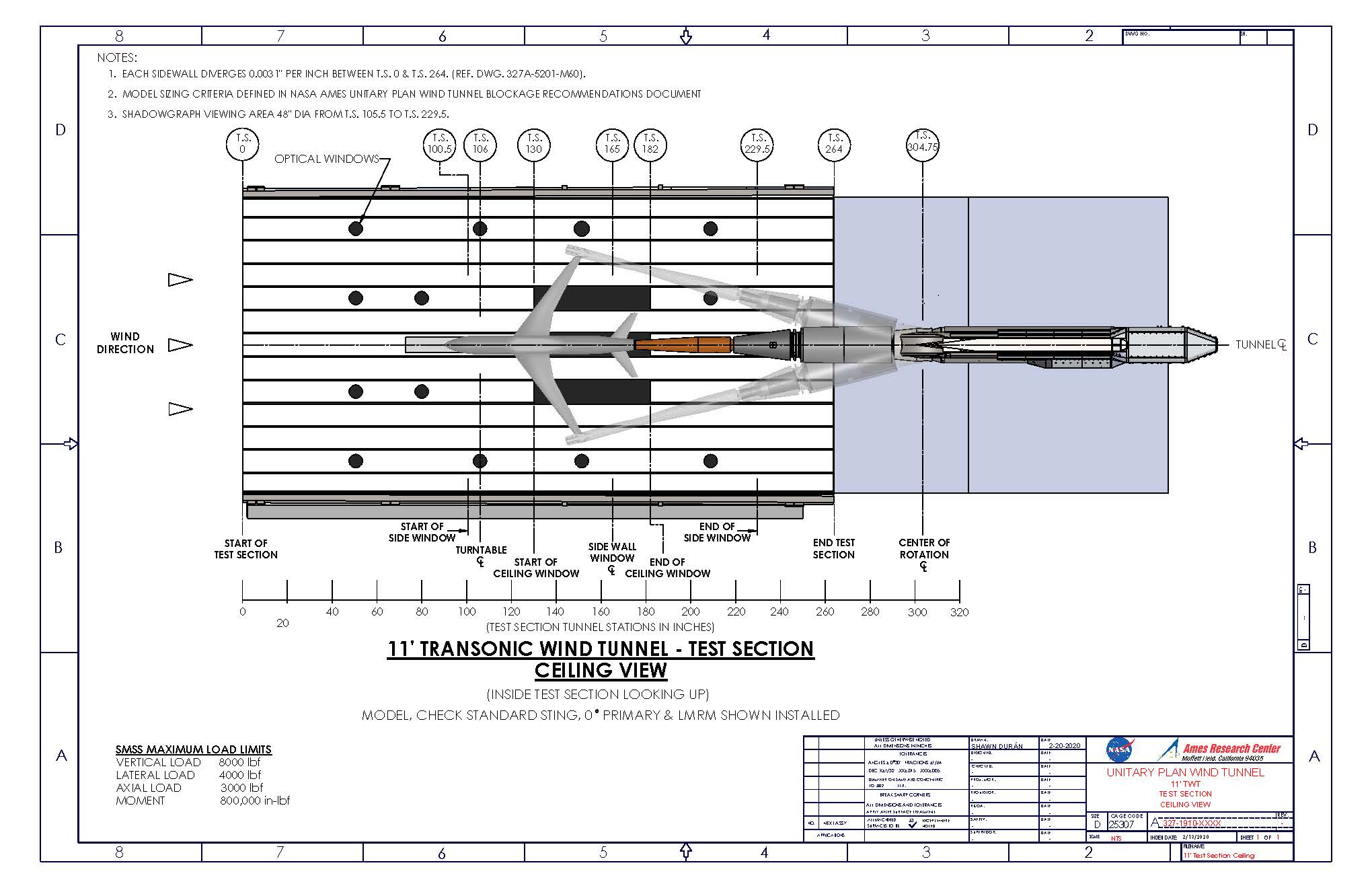
*View 11-ft Transonic Wind Tunnel Test Section Ceiling View dimensions drawing in a new window
![]() Test Section Ceiling Plan View.pdf
Test Section Ceiling Plan View.pdf
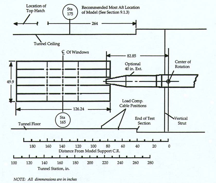
Model Installation Diagram
This diagram shows a sting installed with a 40-inch extension presented in the image below.
Forces and Moment
A traversing strut downstream of the test section can be programmed to translate vertically to maintain a desired point of model-pitch rotation throughout the vertical plane angle-range. The model support center-of-rotation in the horizontal plane is 4.8 inches aft of the strut leading edge. These angles are continuously variable and are determined by the relative positions of a knuckle and sleeve inside the support body.
The model support system can position the model at attitudes circumscribed by a 15-degree half-angle cone. Bent primary adapters of 5, 10, 12.5, and 20 degrees are available to alter the range of model angles. Forces and moments resolved at the model support center of rotation are limited to:
- Vertical: ± 8,000 lbs
- Lateral: ± 4,000 lbs
- Axial: ± 3,000 lbs
- Rolling Moment: ± 104,000 in-lbs
- Combined Vertical and Lateral Bending Moment: ± 800,000 in-lbs
Link to NASA Ames Balance Inventory website
Turntable Model Support
A subfloor-mounted turntable model support, used primarily for semispan model testing, is located at tunnel station 106. This support system can be rotated ± 180 degrees and forces and moments are limited to:
- Lateral force (at a height of up to 24 inches above the floor: ± 50,000 lbs
- Torque (about axis of turntable): ± 500,000 in-lbs
Semispan Testing
Provisions are available for sealing the slots in the test section floor to provide a solid image plane for semispan testing.
NASA Ames SemiSpan Balances and Load Ranges
| Size / Model | NF lbs | PM in-lbs | AF lbs | YM in-lbs | RM in-lbs |
|---|---|---|---|---|---|
| MC-60-27.5 | 6,000 | 36,000 | 1,200 | 60,000 | 300,000 |
| MC-110-27.5 | 11,000 | 90,000 | 2,200 | 132,000 | 660,000 |
| MC-150-27.5 | 15,000 | 120,000 | 3,000 | 180,000 | 960,000 |
| MC-400-27.5 | 40,000 | 240,000 | 8,000 | 480,000 | 2,280,000 |
| ARC-11-30K | 30,000 | 300,000 | 3,000 | 150,000 | 1,350,000 |
Installation and Personnel Access
Models can be installed through a hatch in the top of the test section. Personnel gain access to the test section through doors in the diffuser sidewalls downstream of the model support strut.
Flow Visualization
Flow visualization techniques are available through multiple, optical-quality windows in the tunnel sidewalls. Optical-quality windows are also available in the test section ceiling and floor.
High-Pressure Air
High-pressure air (3,000 psi) is available at weight flows to 80 pounds per second through dual, independently regulated lines ending within the support strut. A one-megawatt, moveable heater can preheat air from one of these lines. Preheated air at 60 pounds per second is available at the turntable.