


Reduced Gravity Drop Towers and Test Rigs
The Zero Gravity Research Facility (ZGF) is located at the NASA Glenn Research Center, in Cleveland, Ohio. This unique facility has been utilized by scientists and engineers for reduced gravity experimentation since 1966. The ZGF has provided fundamental scientific information, has been used in the development of space flight systems and technology, and has been a valuable source of data in the space flight experiment definition process. The facility is available to NASA users, as well as government, academic and commercial users on a fully cost reimbursable basis.
The purpose of this document is to provide information and guidance to prospective Zero Gravity Research Facility experimenters regarding facility capabilities, experiment design, and operational requirements. These guidelines include the following topics; facility description and capabilities, experiment planning, mechanical, electronic, and instrumentation capabilities, documentation and safety requirements, and scheduling, testing, and logistics
Introduction
The Zero Gravity Research Facility is the largest microgravity research drop tower in the world and one of 2 drop towers located at the NASA Glenn Research Center in Cleveland, Ohio. The facility is a National Historic Landmark and has been in operation since 1966. In over 50 years of operation more than 5100 drop tests have been conducted. Tests conducted in the facility have included technology development for cryogenic propellant management, Apollo 13 accident investigation, basic scientific studies of combustion and fluid physics, and the development and checkout of space flight experiment hardware and experiment concepts.
The Zero Gravity Research Facility provides the lowest gravity level of any of NASA’s ground based reduced gravity facilities. The ZGF provides researchers with a near weightless or microgravity environment for 5.18 seconds, as the experiment hardware is allowed to free-fall a distance of 132 meters (433’). The free fall is conducted inside a 143 meter (470’) long steel vacuum chamber. The chamber is 6.1 meters (20’) in diameter and resides inside an 8.1 meter (28’) diameter concrete lined shaft, which extends 155 meters (510’) below ground level. A 5 stage vacuum pumping process is used to reduce the pressure in the chamber to 0.1 torr (760 torr = standard atmospheric pressure). Evacuating the chamber to this low pressure reduces the acceleration, due to aerodynamic drag on the freely falling experiment vehicle, to less than 0.00001 g.
To protect experiment hardware from shock loads experienced during deceleration, an experiment drop vehicle is used as a load bearing structure. The typical drop vehicle is approximately 1 meter in diameter, 3.7 meters in length, and has a gross weight of up to 1100 kg (2400 lbs).
Facility Operations Overview

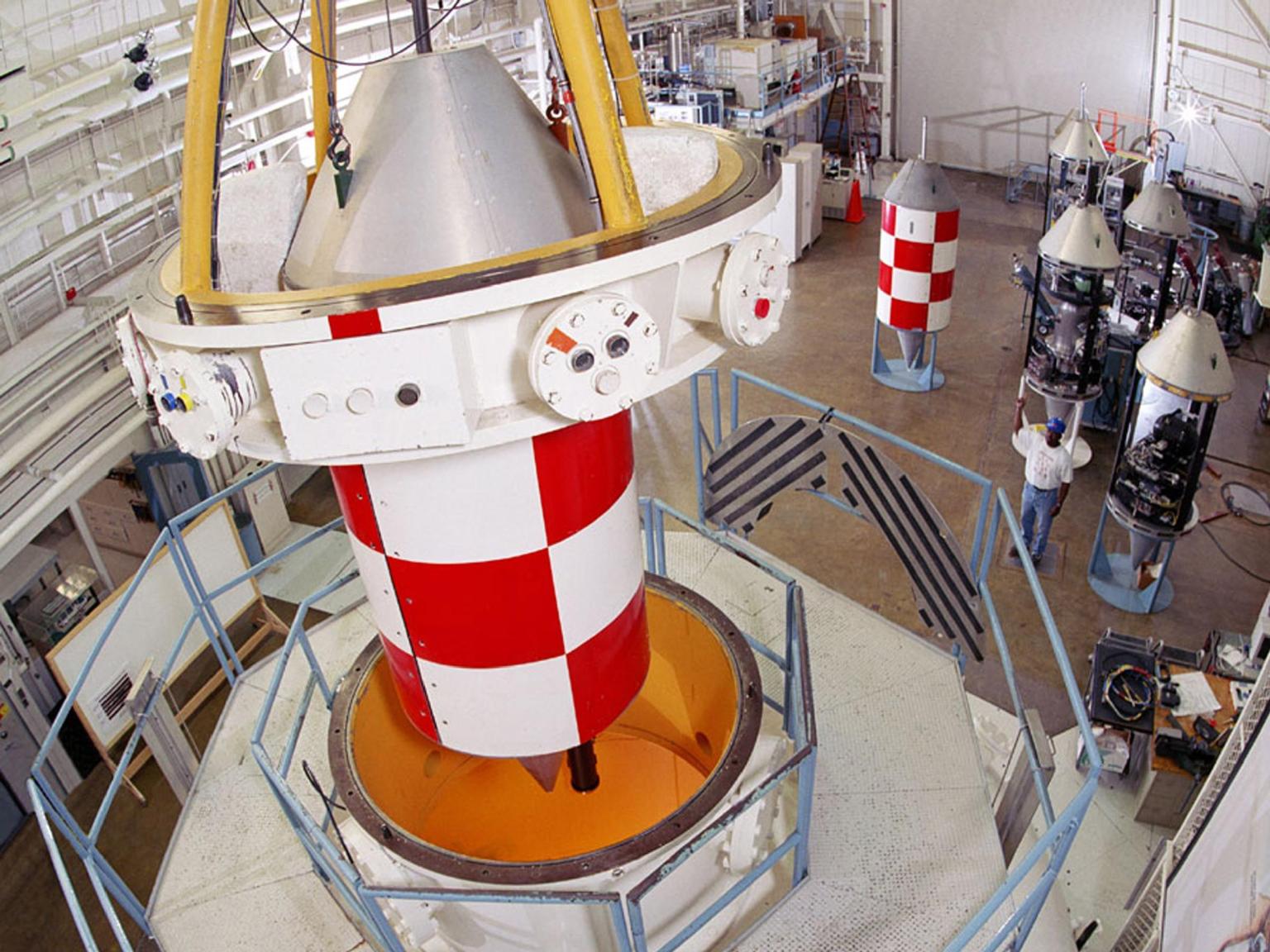
To prepare for a drop, an overhead crane is used to position the experiment vehicle and release mechanism at the top of the vacuum chamber. Once in position, the drop vehicle is connected to the facility control room via an umbilical cable. This cable allows the experiment to be monitored and controlled from the control room until the release sequence is initialized. It takes approximately one hour to evacuate the vacuum chamber. Once the chamber is evacuated, the experiment is readied remotely and the release sequence is initiated. Remotely breaking a specially designed bolt allows the experiment to begin its 132 meter free fall. During the free fall, the drop vehicle carrying the experiment operates autonomously. That is, there are no physical links between the facility and the drop vehicle during the fall. All the necessary systems to power, control, and record the experiment are contained on the drop vehicle. A wireless video link allows two NTSC video channels to be displayed and recorded in the facility control room during the free fall, enabling the control room occupants to observe the experiment in real time.
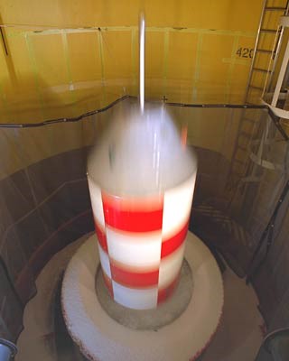 A decelerator cart, 1.35 m (4.5 ft) in diameter and approximately 5.8 meters (20’) deep, stops the fall of the experiment vehicle. The cart is filled with expanded polystyrene beads that dissipate the kinetic energy of the experiment vehicle, which enters the cart traveling approximately 50 m/s (113 mph). The vehicle is stopped in approximately ~4.5 meters of expanded polystyrene and experiences an average deceleration rate of 35 g, with peak decelerations reaching to 65 g. After the drop, the vacuum chamber is returned to atmospheric pressure and the experiment vehicle is retrieved and returned to the shop floor using the facility overhead crane. The process of preparing the experiment for the drop, installing the experiment and release mechanisms on top of the vacuum chamber, pumping down the chamber, executing the drop, and retrieving the drop vehicle can take 3 to 4 hours. Therefore, a maximum of two drops can be completed in a standard 8 hour work day.
Once an experiment has been installed and checked out on the drop vehicle, the drop vehicle will be balanced about its vertical centerline using the facility’s custom drop vehicle balance stand. This will ensure that the drop vehicle hangs straight down when positioned in the release mechanism at the top of the vacuum chamber. Following the completion of the balance, drop testing can begin. The typical timeline for the facility two drop day is as follows:
Drop 1:
-
- 7:00-8:30: Pre-drop experiment preparation by experiment and facility teams
- 8:30-9:00: Install drop vehicle on top of vacuum chamber and close vacuum chamber.
- 9:00-10:00: Evacuate chamber
- 9:50-10:10: Power up experiment, execute pre-drop checkout and pre-drop procedures.
- 10:10: Drop Experiment
- 10:15-10:30: Return vacuum chamber to atmospheric pressure
- 10:30 – 11:00: Retrieve drop vehicle and return to shop floor
- 11:00 – 12:45: Refill decelerator cart with Expanded Polystyrene
- 11:15: Experiment Team has access to drop vehicle
Drop 2:
-
- 11:15 – 12:45: Pre-drop experiment preparation for 2nd drop
- 12:45 – 1:15: Install drop vehicle on top of vacuum chamber and close vacuum chamber.
- 1:15 – 2:15: Evacuate chamber
- 2:05 – 2:25: Power up experiment, execute pre-drop checkout and pre-drop procedures.
- 2:25: Drop Experiment
- 2:30 – 2:45: Return vacuum chamber to atmospheric pressure
- 2:45 – 3:15: Retrieve drop vehicle and return to shop floor
- 3:15 – 4:00: Refill decelerator cart with Expanded Polystyrene
- 3:30: Experiment Team has access to drop vehicle
Drop Vehicles
Drop vehicles provide a load bearing structure on which to mount the experimental hardware to be tested in the ZGF. The typical drop vehicle is approximately 1 meter in diameter, 3.7 meters in length, and has a gross weight of up to 1100 kg (2400 lbs).
The drop vehicle also contains the power, control, imaging, and data acquisition equipment used to support the experiment. Currently 7 drop vehicles are available to support experiments at the ZGF. The drop vehicles provide a load bearing structure to which to attach the experiment hardware and protect the hardware from the deceleration loads that are experienced at the end of the free fall. All hardware shall be designed to withstand the peak deceleration load of up to 65g. The drop vehicles have a maximum gross weight of 2400 lbs. Up to 1000 lbs. of experiment hardware can be installed, depending on the drop vehicle. As much as possible, user supplied hardware shall be laid out to facilitate the balancing of the assembled drop vehicle.
In addition to the equipment specific to the drop vehicles described below, each drop vehicle can be equipped with a Programmable Logic Controller, 24 VDC battery packs, 24 VDC to 12 VDC, 5 VDC, or 15 VDC converters, video recorders, and a data acquisition system.
Experiment Power
Experiments are typically powered by 24 VDC battery packs. The battery packs provided are rated at 5 ampere/hours. Electrical loading is minimized by only turning on critical systems after the one hour vacuum chamber pump down is completed.
In addition to the battery packs, other DC voltages are commonly supplied including regulated 5, 12, 15, and 24 volts. Custom power solutions can be developed and provided by the facility staff and have included custom DC voltages as well as ties to 115 VAC and high voltage power sources which can be provided prior to drop through the drop vehicle umbilical connection.
Experiment Control
At present, electrical systems on all of the drop vehicles are controlled by Automation Direct D0-06DR-D Programmable Logic Controllers (PLCs). The PLCs can receive DC inputs ranging from 12-24 VDC and have four isolated commons for switching 6-27 VDC. For most of the drop vehicles, 24 VDC is used for all PLC output control and inputs to simplify the electrical system. The PLC runs on Automation Direct DirectSoft programming software. Automatic sequence control is provided by the PLC prior, during, and after the experiment package is dropped. Manual PLC functions are controlled using AutomationDirect C-more HMI touchscreens when connected via Ethernet. There is a touchscreen in the control room, for experiment setup prior to dropping, and on a maintenance cart that can be wheeled right up to the drop vehicle for 1G experiment checkout and testing, while the drop vehicle sits on a stand.
Data Acquisition
Analog signals from commercial instrumentation such as pressure transducers, thermocouples, flow meters, accelerometers, etc. are typically recorded using National Instruments CompactDAQ cDAQ-9132 4-slot chassis, a ruggedized DAQ system, programmed using Labview. The cDAQ-9132 is capable of recording 16 differential analog channels, at a maximum sampling rate of greater than 15kHz. Maximum input voltage ranges are +/-10V. Analog inputs are unfiltered. The cDAQ-9132 also can record 8 thermocouple channels. This DAQ system functions as a stand-alone system. Data is recorded to a SD flash card on-board the cDAQ and can be accessed remotely using the Windows Remote Desktop feature. Data is processed post drop and results in a tab-delimited file which is easily opened by Excel, as an example. Other customer provided or custom data acquisition solutions can be incorporated as required.
Video Imaging
Video images from a wide range of video camera formats can be recorded by facility provided hardware on the drop vehicles. Video formats include USB3, GigE, NTSC, SDI, SD, and HD. GigE and USB3 video is acquired using an RTD PCle-104 ruggedized industrial computer running commercial frame grabbing software. A limited number of GigE and USB3 cameras may be available for customer use. These devices include the Allied Vision Technologies GC1380CH, Prosilica GT1920 & GT1930C, Dalsa Nano G3-GM10-M2590, Basler scA780-54gc, and Flir Grasshopper3 cameras. The frame grabbing software provides 1936 x1456 resolution footage at 30 FPS but higher frame rates are possible depending on customer needs. Exposure and gain for the cameras are controlled using Norpix Streampix software. HD digital video cameras from SJCAM and GoPro, with on board recording capability, have also been successfully utilized in the facility. Up to 2 NTSC video signals can be transmitted wirelessly from the falling drop vehicle to the control room, allowing control room occupants to view the experiment live. These transmitted images can also be recorded in the control room for immediate replay following a drop or for backup to the onboard recording capability.
Vehicle Descriptions
Each drop vehicle provides some unique capabilities and is identified by a letter designation. Four of the drop vehicles contain environmental chambers which have been used to contain combustion or biological experiments. A description of each drop vehicle and its unique capabilities follows.
“B” Drop Vehicle:
The B drop vehicle contains a high pressure Inconel 625 environmental chamber and will typically be used for liquid droplet combustion and supercritical oxidation type experiments at high temperatures and pressures. The chamber has a volume of 260 cubic inches and is rated for a maximum operating pressure of 5000 psig, at 1000 deg. F.
Heaters integral to the pressure vessel allow the interior of the chamber to be heated to 1200 deg F. A flow system integral to the drop vehicle supplies oxidizer, inert gas, and fuels to the vessel at the appropriate temperatures and pressures. A NAC HX-7 high speed video camera images the combustion event at frame rates up to 3600 fps. (This drop vehicle is currently in development for fall 2018 testing).
“D” Drop Vehicle:
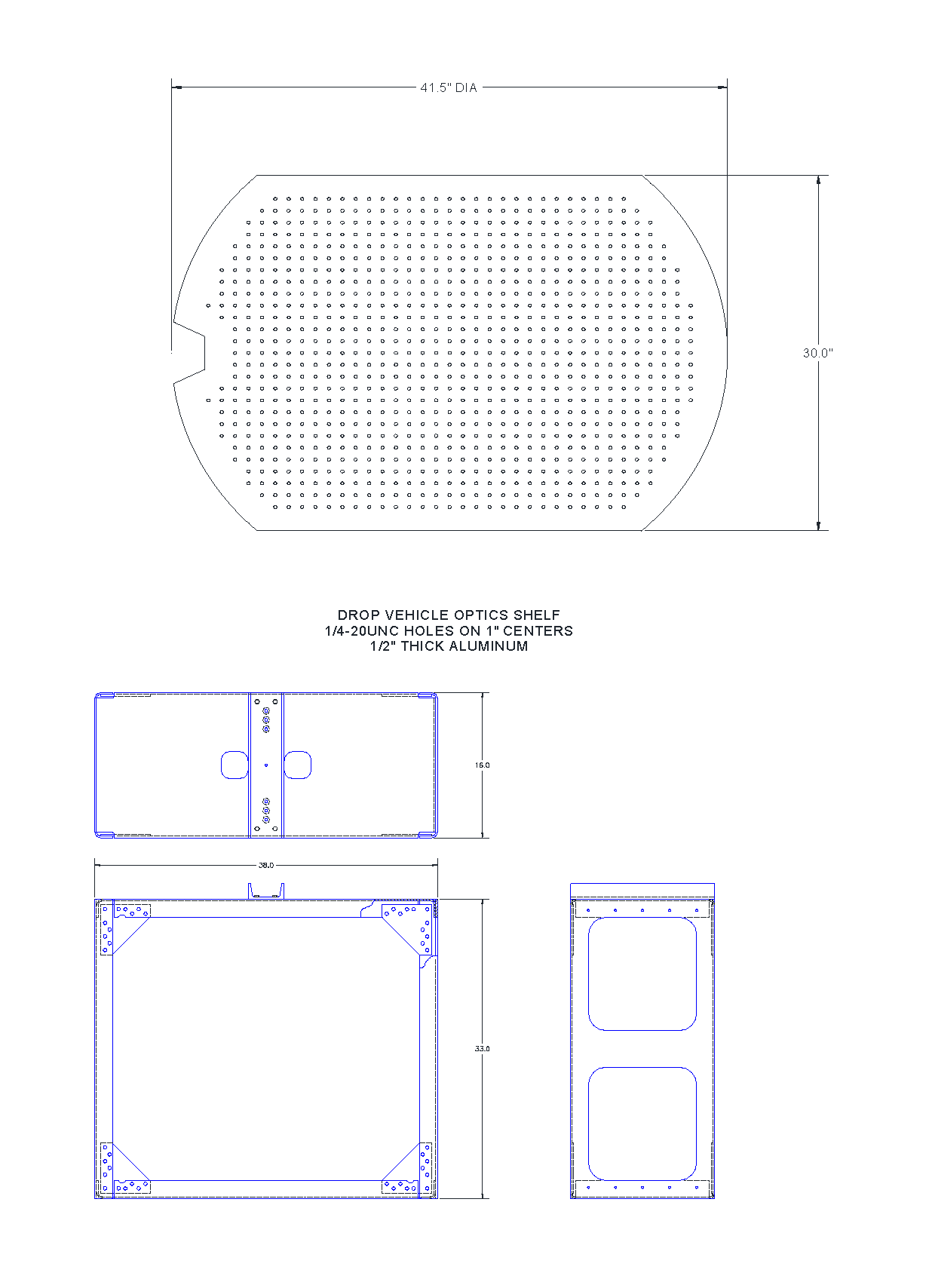
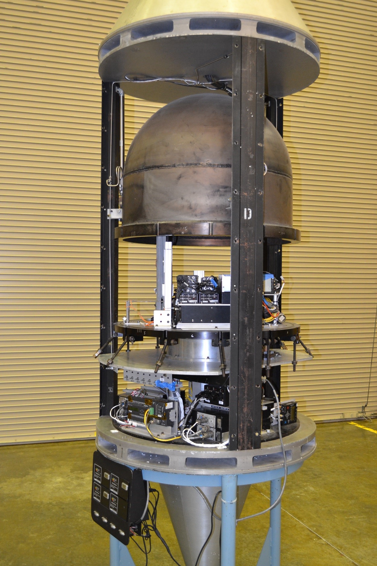 The D drop vehicle contains an aluminum environmental chamber on a rotating plate to create partial gravity during the drop. It has typically been used to support combustion/fire safety investigations with solid, liquid, or gaseous fuels. An ASME code stamped pressure vessel, 32” in diameter and 30” tall, mounted to a turntable type arrangement is installed on the center line of this drop vehicle. The vessel has a maximum allowable working pressure of 35 psig at 70 deg. F. The D drop vehicle offers a unique capability in that it can be rotated, creating a centrifuge in which to conduct tests in partial gravity. A stepper motor and motor controller drive the rotating vessel via a gear and chain arrangement. Setting the rotational speed of the vessel between 10 and 347 degrees/second creates artificial gravity levels between 0.001 and 1.1 times the earth’s gravitational acceleration at a 30 cm radius from the center of the base plate. The centrifuge is brought up to speed while the drop vehicle is hanging at the top of the facility. Sensors on board the drop vehicle provide acceleration and rotational speed data and provide an indication as to whether the centrifuge has reached the desired, steady state rotational speed. After it has been verified that the centrifuge is running at the proper speed, the combustion experiment is initiated and the drop vehicle released. The chamber also includes a small gas flow system for storing and delivering fuels or other gases. The flow system utilizes a 75 cc DOT sampling cylinder for gas storage at pressures up to 200 psig.
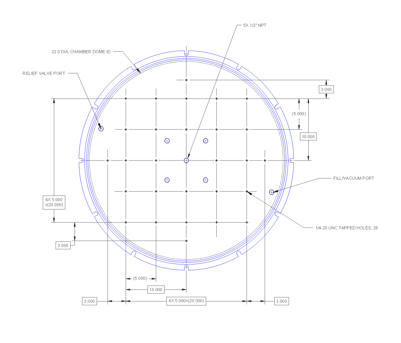
Experimental hardware is mounted to the chamber base plate and is limited in height by the hemispherical dome, which is 28” high at the center. The D drop vehicle is shown in figure 4 and a layout of the base plate is shown in the figure below.
“H” Drop Vehicle:
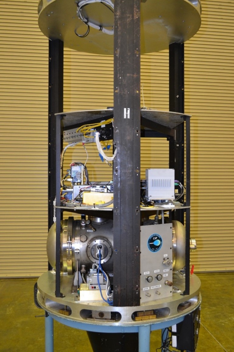 The H Drop Vehicle contains a stainless steel environmental chamber and has typically been used for liquid droplet combustion or biological experiments. The cylindrical chamber is 23.75” long with an internal diameter of 12.37”, and has semi-hemispherical end caps. The chamber has an internal volume of approximately 3700 cubic inches and maximum working pressure of 87 psig at 70 deg. F. An insert for this chamber has been specifically designed for the deployment and combustion of liquid fuel droplets. Small droplets can be deployed on a glass fiber and then ignited via a hot wire. The deployment needle and hot wire can be retracted from the combustion area to minimize their effects on the combustion process. Two HD video cameras image the droplet deployment, ignition and combustion. In addition, the droplet fiber can be translated through the combustion vessel creating forced flow of the oxidizer environment across the droplet. Translation velocities can be created from 0 to 7 cm/s. Combustion with solid fuels and real time fluorescent imaging of biological samples have also been accomplished in this environmental chamber. The top shelf of the H drop vehicle is open allowing for the installation of additional customer specific hardware or instrumentation.
“G” Drop Vehicle:
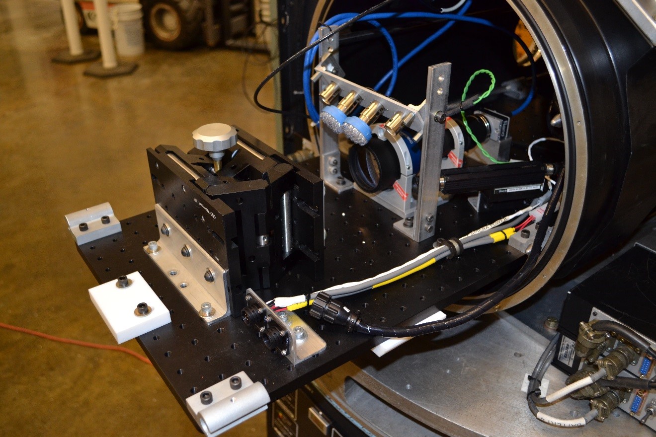 The G drop vehicle contains an aluminum environmental chamber which can be used to house combustion, biological, fluid, or other applicable experiments. The chamber has an internal volume of approximately 6400 cubic inches and a maximum operating pressure of 120 psig at 150 deg F. The chamber has three orthogonal, 4.5” diameter windows, located at the center of the chamber for imaging the experiment inside. The chamber is also equipped with the appropriate feed thrus such that imaging equipment can be mounted inside the chamber, when the chamber test environment allows. The chamber is mounted horizontally on the drop vehicle. A 32” x 13” optics plate, with 1” O.C., ¼-20UNC tapped holes is available for installation of experiment hardware inside the chamber. The optics plate attaches to internal rails which enables the experiment to slide in and out of the chamber for easy access.
“M” Drop Vehicle:
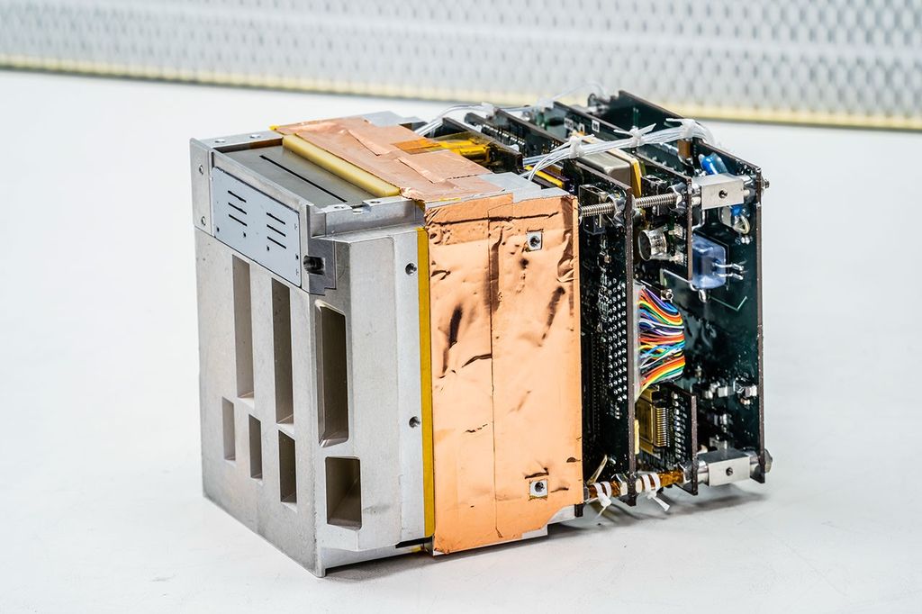
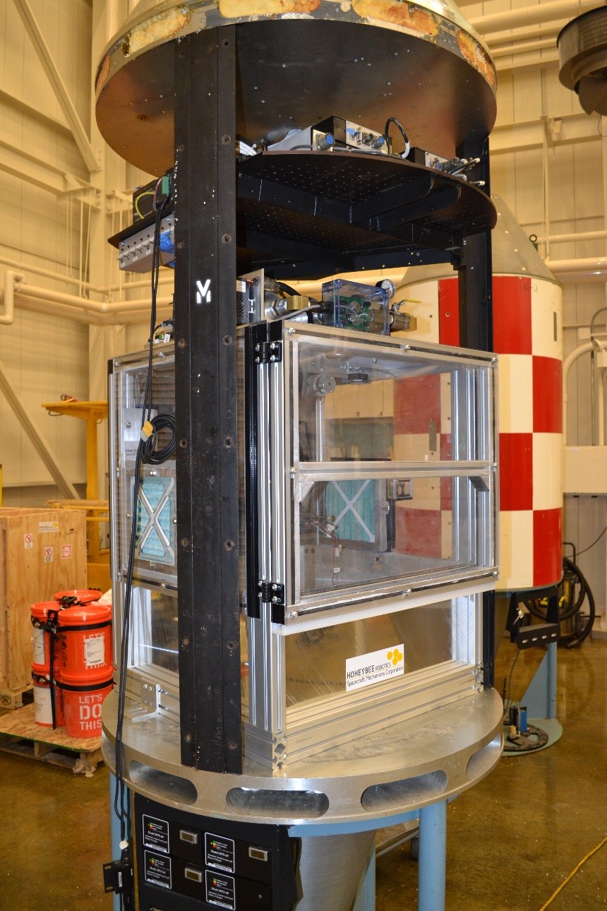 The M drop vehicle provides the largest volume to accommodate customer developed hardware. Experiment hardware up to 37” in diameter and 60” tall can be attached directly to the bottom flange of this drop vehicle. Hardware installed can weigh up to 500 lbs. A shelf above the experiment contains power, control, and data acquisition capabilities for the payload below. Figure 7 shows the M drop vehicle with a customer developed payload installed.
“X” Drop Vehicle:
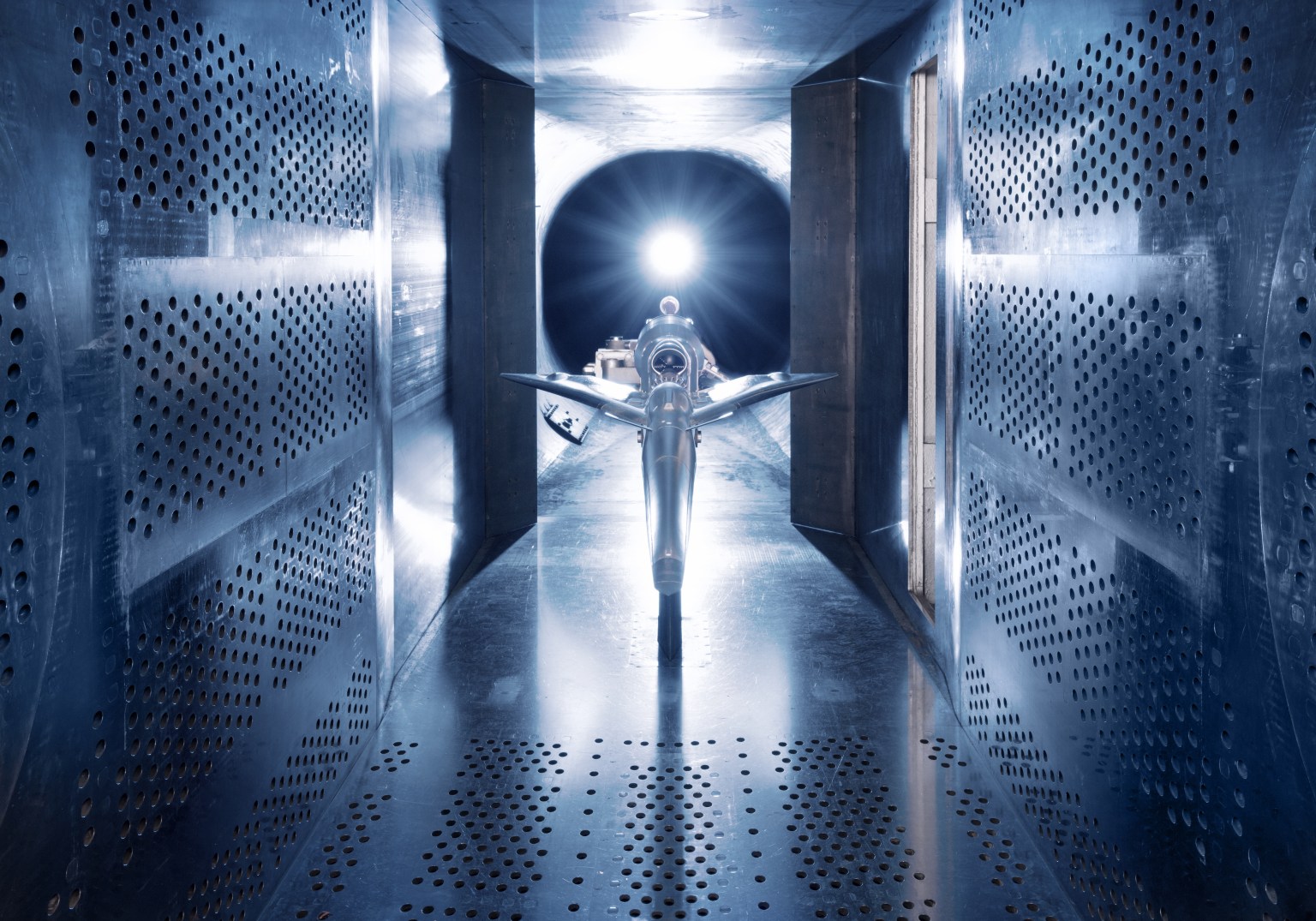
 The X drop vehicle is designed to rapidly accept experiments assembled in drop frames designed for the GRC 2.2 second Drop Tower, as is the X2 drop vehicle, described below. The X drop vehicle currently houses the Microgravity Wind Tunnel in a 2.2 s drop frame, which provides a 20 cm diameter flow duct and gas supply bottles to provide up to 30 cm/s of oxidizer flow, of up to 100% oxygen at pressures up to 14.7 psia, through the duct. Two 4 liter bottles can be filled to 1300 psia with oxygen-diluent mixtures. The flow velocity is controlled through a critical flow orifice that can be changed to control flows from 1 mm/s to 30 cm/s. A small 1 liter bottle and flow system is also mounted on the rig to provide a second source of gas to the chamber. It has been used to provide local nitrogen extinguishment, but could also be used with other gases. A back pressure control valve maintains a set pressure in the duct relative to the facility vacuum in the drop shaft, and the experiment vents to the vacuum through this valve. Two long orthogonal windows allow visible imaging with multiple cameras, including two GIGE cameras. Flow system pressures and igniter power are recorded. Four type K thermocouples are recorded as well as flow system temperature. The control system allows for 1g or 0g ignition, manual or automatic flow bottle switching, and manual pressure control in 1g. LED lighting provides sample and smoke illumination and a reference light for video imaging. The drop vehicle is currently used for spacecraft fire safety testing.
“X2” Drop Vehicle:
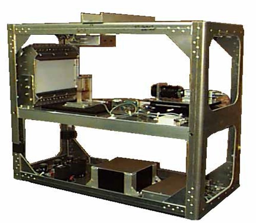
The X2 drop vehicle is also designed to rapidly accept experiments assembled in the 2.2 s drop tower frames or experiments assembled on a drop vehicle optical breadboard plate. The primary difference between X and X2 is that the X drop vehicle is 0.4 m (16 inches) taller, allowing more free space above the experiment for access from the top for experiments that require it. This compatibility allows for the rapid integration of 2.2 s Drop Tower experiments into the Zero G Facility for longer duration tests. For experimenters desiring to develop and integrate their experiment independent of the drop vehicle, a drop tower frame or breadboard shelf can be provided to experimenters allowing them to assemble their experiment at their location. This allows experimenters to assemble their test hardware off site and then to quickly integrate their test hardware into the drop vehicle, leaving only connections to the drop vehicle power, control, and
data acquisition functions. Experiments designed for use in both the 2.2 s Drop Tower and ZGF must be capable of handling these additional constraints associated with the Zero G Facility; operation in a vacuum, greater deceleration loads – up to 65 g, possible longer operational time on battery power, and remote control operation. The breadboard shelf and drop tower frame are shown in the figure below.
Test Rigs
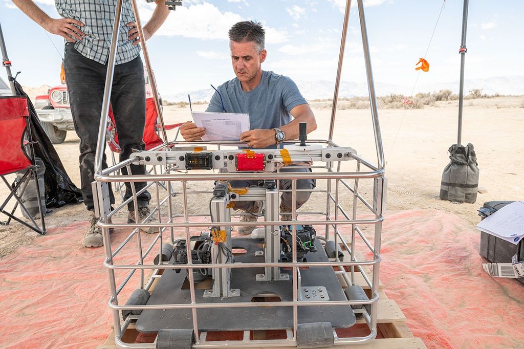
Educational Drop Tower Rig
The test operations at the 2.2 Second Drop Tower are subject to the Glenn Safety Permit System. The objectives of this system are to avoid undue risks, injury to personnel, damage to property, or disruption of operations. Additional safety concerns may be raised during review of the experiment design. These issues will be addressed on a case-by-case basis.
- Dangerous or hazardous chemicals (including radioactive materials) or chemical reaction products must not be used in the
- Any chemicals and all materials must be contained within the experimental
- All proposed combustion experiments will be reviewed by a NASA panel on a case-by-case This is not meant to discourage combustion experiments, but rather to ensure safe operations of the experiment and the drop tower.
- Biological samples, for the most part, may not be used in the experiment, except for common household products (e.g., cotton). Live animals, even insects, are not acceptable. All materials will be reviewed by a NASA
The experiment apparatus needs to withstand repeated shock loads of 25 g’s (245 m/s2).
NASA will supply the following equipment, as required, to be used for each investigator’s experiment:
- The Mounting Adaptor Plate measures 12 in by 12 in by 0.5 in (30.54 cm by 30.54 cm by 27 cm). It is made of black anodized precision machined aluminum. There is a 12 by 12 matrix on 1.00 in centers. The Mounting Adaptor Plate weight is 6.8 pounds.
- An acrylic containment chamber is available to be place on mounting adapter plate. The internal measurements are 9.25 in wide x 11 in deep x 11.25 in high. (23.49 cm x 27.94 cm x 28.57cm), The experiment must fit through an opening 8 in wide x 9.625 in high (20.32 cm x 24.52 cm). Items are fastened to bottom off the container using Velcro.
The mass of the experiment apparatus), including all experiment fluids, cables, connectors, mounting adaptor plate, etc., must be less than or equal to 25 pounds (11.4 kg.
The layout of mounting adapter plate for the experiment, lighting, and camera are shown in Figure 2.
Electrical power is supplied by a 28-volt (nominal) lead-acid battery. Power is available as 28-volt DC (+/- 2 v) and 12-volt DC (+/- 0.25 v). The maximum current from the 28-volt source is 8 amperes and from the 12-volt source is 1 ampere. The 28 VDC and 12 VDC power sources are electrically isolated from each other.
A camera system capture and records images at a minimum of 30 images per second. Illumination is provided by either a backlight panel or a front lighting the test object.
Centrifuge ZGF Rig
The centrifuge is a drop rig with a 300-liter combustion chamber that can be rotated to generate artificial gravity (through centrifugal acceleration). Power is transferred inside the rotating chamber via a slip ring.
- Chamber: Maximum inside diameter: 81.28 cm
- Cylindricalchamber 30.48 cm high, capped by hemispherical top with 81.28 inside diameter (internalvolume: 299 L)
- Up to 2 atmospheres pressure
- Up to 40% Oxygen
- Rotation: Maximum centrifugalacceleration: 1100 cm/s2 (1.1 gEarth) at a 30 cm radius (347 deg/s)
- Minimum centrifugalacceleration: 1 cm/s2 (10-3 gEarth) at a 30 cm radius (10 deg/s)
- Rotation speed set and measured with an accuracy that provides 10-4gEarth resol
- Power available on rotating plate: Allinternalcomponents for data acquisition (video, data logger, etc.) and experiment power (igniter coil and solenoid)
- Internalsensors (thermocouples, radiometers, etc.)
Four cameras plus an additional set-up camera
Combustion Tunnel Drop Tower Rig
The droppable wind tunnel at NASA GRC is mounted in a 2.2 s drop tower frame that is further mounted on a ZGF drop vehicle with the addition of a back pressure valve to maintain chamber pressure in the vacuum of the ZGF drop facility. It can thus be used in the 2.2 s drop tower at ambient pressure or in the ZGF 5.18 s drop facility at variable pressures.
The wind tunnel consists of a ~20-cm-diameter vertically mounted flow duct with two orthogonal ~ 30 cm windows for experiment viewing. The apparatus allows flow velocity (0 – ~28 cm/s), oxygen (0 – 100%), and pressure (0 – ~1 atm) variation. Gravity instantaneously changes from normal gravity to microgravity at the start of the drop.
Two on-board 4 L gas bottles may be filled with different oxygen concentrations allow the test gas to change during a test via a remotely controlled three-way valve. This feature is commonly used for extinction testing where the first gas is a flammable mixture and the second gas is the near-extinction test gas. The flow must be fast enough that the test gas reaches the sample in the test time.
The flow rate through the test section is controlled by a critical flow orifice (3 sizes cover the flow range) and upstream of the orifice pressure regulator. Each bottle has its own regulator, so it is possible to step change the velocity through the test section, although the chamber pressure may transiently vary if the change is too large, and this feature is rarely used.
The backpressure valve uses an MKS pressure transducer to control chamber pressure. The valve response time is too long to change pressure quickly enough during a 5.18- s drop but can be used in normal gravity testing to vary pressure during a 1g test.
Two high resolution orthogonal high speed color cameras are available on the drop rig along with lower resolution cameras to provide video during the drop test. LED lighting is available on the rig.
Digital data: There are four type-K thermocouple channels available on the rig. Pressure readings are recorded of 2 bottle pressures, orifice pressure, plenum pressure, and chamber pressure. Ignition current is recorded. An accelerometer provides a g level measurement.