


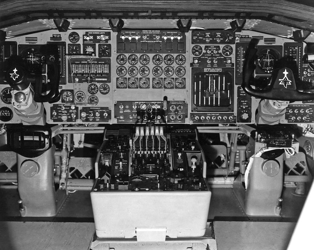
ED97-44244-1
The XB-70 #1 cockpit, which shows the complexity of this mid-1960s research aircraft. On the left and right sides of the picture are the pilot’s and co-pilot’s control yokes. Forward of these, on the cockpit floor, are the rudder pedals with the NAA (North American Aviation) trademark. Between them is the center console. Visible are the six throttles for the XB-70’s jet engines. Above this is the center instrument panel. The bottom panel has the wing tip fold, landing gear, and flap controls, as well as the hydraulic pressure gages. In the center are three rows of engine gages. The top row are tachometers, the second are exhaust temperature gages, and the bottom row are exhaust nozzle position indicators. Above these are the engine fire and engine brake switches.
The instrument panels for the pilot (left) and co-pilot (right) differ somewhat. Both crewmen have an airspeed/Mach indicator, and altitude/vertical velocity indicator, an artificial horizon, and a heading indicator/compass directly in front of them. The pilot’s flight instruments, from top to bottom, are total heat gage and crew warning lights; stand-by flight instruments (side-slip, artificial horizon, and altitude); the engine vibration indicators; cabin altitude, ammonia, and water quantity gages, the electronic compartment air temperature gage, and the liquid oxygen quantity gage. At the bottom are the switches for the flight displays and environmental controls.
On the co-pilot’s panel, the top three rows are for the engine inlet controls. Below this is the fuel tank sequence indicator, which shows the amount of fuel in each tank. The bottom row consists of the fuel pump switches, which were used to shift fuel to maintain the proper center of gravity. Just to the right are the indicators for the total fuel (top) and the individual tanks (bottom). Visible on the right edge of the photo are the refueling valves, while above these are switches for the flight data recording instruments.1965NASA Photo / North American photo› XB-70 Project Description