


![Request for Information – Potential [Placeholder for Prize]](https://assets.science.nasa.gov/dynamicimage/assets/science/psd/solar/2023/09/s/solarsystem_0.jpg?w=1024)


Chapter Contents
- Chapter Glossary
- 9.1 Introduction
- 9.2 State-of-the-art: Radio Frequency Communications
- 9.3 State-of-the-art: Free Space Optical Communications
- 9.4 Future Technologies
- 9.5 Summary
- References
Chapter Glossary
| (ADCS) | Attitude Determination and Control System |
| (BPF) | BandPass Filters |
| (CDH) | Command and Data Handling |
| (COTS) | Commercial-off-the-Shelf |
| (DORA) | Deployable Optical Receiver Aperture |
| (DLR) | German Aerospace Center |
| (DSN) | Deep Space Network |
| (DSP) | Digital Signal Processing |
| (DVB-S2) | Digital Video Broadcast Satellite Second Generation |
| (FCC) | Federal Communications Commission |
| (FIPS) | Federal Information Processing Standard |
| (FPGAs) | Field Programmable Gate Arrays |
| (FSM) | Fine-steering Mirror |
| (FSO) | Free Space Optical |
| (IARU) | International Amateur Radio Union |
| (IEEE) | Institute of Electrical and Electronics Engineers |
| (ISARA) | Integrated Solar Array and Reflectarray Antenna |
| (ISM) | Industrial, Scientific, and Medical |
| (ISOC) | Inter-spacecraft Optical Communicator |
| (ISS) | International Space Station |
| (JAXA) | Japanese Aerospace Exploration Agency |
| (JPL) | Jet Propulsion Laboratory |
| (LADEE) | Lunar Atmosphere and Dust Environment Explorer |
| (Lasercom) | Laser Communications |
| (LCH) | Laser ClearingHouse |
| (LCT) | Laser Communication Terminals |
| (LDPC) | Low-Density Parity-check Code |
| (LLCD) | Lunar Laser Communications Demonstration |
| (LNA) | Low Noise Amplifier |
| (LSRB) | Laser Safety Review Board |
| (MA) | Multiple Access |
| (MarCO) | Mars Cube One |
| (MEMS) | Micro-Electro-Mechanical Systems |
| (MRR) | Modulating Retro-Reflector |
| (NEN) | Near Earth Network |
| (NICT) | National Institute of Information and Communications Technology |
| (NOAA) | National Oceanic and Atmospheric Administration |
| (NPR) | NASA Procedural Requirements |
| (NSN) | Near Space Network |
| (NTIA) | National Telecommunications and Information Administration |
| (OCSD) | Optical Communication and Sensor Demonstration |
| (OCTL) | Optical Communication Telescope Laboratory |
| (OSIRIS) | Optical Space Infrared Downlink System |
| (PAT) | Pointing, Acquisition, and Tracking |
| (RF) | Radio Frequency |
| (SBIR) | Small Business Innovative Research |
| (SCaN) | Space Communications and Navigation |
| (SDR) | Software Defined Radios |
| (SME) | Subject Matter Expert |
| (SNR) | Signal-to-Noise Ratio |
| (SOTA) | Small Optical Transponder |
| (SWaP) | Size, Weight, and Power |
| (TDRS) | Tracking and Data Relay Satellite |
| (TMA) | Technology Maturity Assessments |
| (TRL) | Technology Readiness Levels |
| (TT&C) | Tracking, Telemetry & Command |
| (USTP) | University Smallsat Technology Partnerships |
| (VSOTA) | Very Small Optical Transponder |
| (WFF) | Wallops Flight Facility |
9.1 Introduction
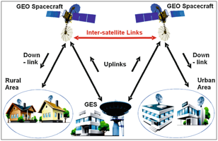
For most missions, the communication system enables the spacecraft to transmit data and telemetry to Earth, receive commands from Earth, and relay information from one spacecraft to another. A communications system consists of the ground segment—one or more ground stations located on Earth—and the space segment—one or more spacecraft and their respective communication payloads. The three functions of a communications system are receiving commands from Earth (uplink) and transmitting data down to Earth (downlink), and transmitting or receiving information from another satellite (crosslink or inter-satellite link) (Figure 9.1). There are two types of communication systems: radio frequency (RF) and free space optical (FSO); FSO is also referred to as laser communications (lasercom).
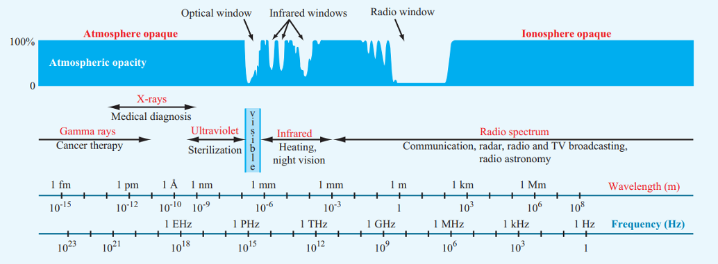
Most spacecraft communications systems are radio-frequency-based. They typically operate within the designated Institute of Electrical and Electronics Engineers (IEEE) radio bands of 300 MHz to 40 GHz. RF systems communicate by sending data using electromagnetic waves to and from antennas. Information is modulated onto radio frequency electromagnetic waves and sent over a channel, through the atmosphere or space, to the receiving system where it is demodulated (Figure 9.2).
Although RF systems are typically used for low-rate space communication, recent developments in FSO communications have made FSO a compelling alternative to RF systems, particularly for high-rate communication. FSO systems consist of a transmitting terminal and receiving terminal. Like an RF system, information is modulated onto electromagnetic waves (at optical frequencies) and sent over a channel to the receiving system. FSO links operate at higher frequencies than RF links, generally in the near-infrared bands (e.g., 1064 nm or 1550 nm). Visible light is often not used due to eye safety concerns for technicians at the terminals. The use of higher frequencies and wider bandwidths can support higher data rates, but the shorter wavelengths also result in narrower beamwidths that require more accurate pointing towards the communication terminal with greater accurately and precisely.
This chapter organizes the state-of-the-art in small spacecraft communications technologies into two main categories: RF and FSO. Tables at the end of each section list hardware options for RF and developing FSO technologies for mission designers to consider.
The information described below is not intended to be exhaustive, but provides an overview of current state-of-the-art technologies and their development status for a particular small satellite subsystem. The list of organizations/companies in this chapter is not all-encompassing and does not constitute an endorsement from NASA. There is no intention of mentioning certain companies and omitting others based on their technologies or relationship with NASA. The information is for awareness and guidance only. The performance advertised may differ from actual performance since the information has not been independently verified by NASA subject matter experts and relies on information provided directly from the manufacturers or available public information. It should be noted that TRL designations may vary with changes specific to the payload, mission requirements, reliability considerations, and/or the environment in which performance was demonstrated. Readers are highly encouraged to reach out to companies for further information regarding the performance and TRL of the described technology.
9.2 State-of-the-art: Radio Frequency Communications
A radio communication system includes a radio transmitter, a free-space communication channel, and a radio receiver. At the top level, a radio transmitter system consists of a data interface, modulator, power amplifier, and an antenna. The transmitter system uses the modulator to encode digital data onto a high-frequency electromagnetic wave. The power amplifier then increases the output RF power of the transmitted signal to be sent through free space to the receiver using the transmit antenna.
The radio receiver system uses a receiving antenna, low-noise amplifier, and demodulator to produce digital data output from the received signal. The receiving antenna collects the electromagnetic waves and routes the signal to the receiver, which then demodulates the wave and converts the electrical signals back into the original digital message. Low-noise amplifiers are sometimes employed to minimize thermal noise in certain frequency bands and/or increase the received signal strength. In many cases, the functions of the modulator and demodulator are combined into a radio transceiver that can both send and receive RF signals.
Radio frequency communications for spacecraft are conducted between approximately 30 MHz and 60 GHz. The lower frequency bands (up to S-band) are typically more mature for SmallSat use; however, extensive use of these bands has led to crowding and challenges in acquiring licensing. Higher frequencies offer a better ratio of gain-to-aperture-size, but this is offset by the increased atmospheric attenuation at those frequencies and the higher free space loss that is directly proportional to the square of the frequency.
9.2.1 Frequency Bands
Satellite communications are conducted over a wide range of frequency bands. The typical bands considered for small satellites are UHF, S, X, and Ka. The most mature bands used for CubeSat communication are VHF and UHF frequencies. There has been a shift in recent years towards S and X, with Ka-band also being used for recent and future small satellite communications. The move to higher frequency bands has been driven by a need for higher data rates. At the higher frequencies, there is generally greater atmospheric and rain attenuation adding to increased free space loss. This needs to be compensated for with higher power transmission and/or higher gain antennas with narrower beamwidths. Moving to higher-gain antennas increases the pointing accuracy required for closing the link. See Table 9-1 for a list of RF bands.
| Table 9-1: Radio Frequency Bands | |
|---|---|
| Band | Frequency |
| VHF | 30 to 300 MHz |
| UHF | 300 to 1000 MHz |
| L | 1 to 2 GHz |
| S | 2 to 4 GHz |
| C | 4 to 8 GHz |
| X | 8 to 12 GHz |
| Ku | 12 to 18 GHz |
| K | 18 to 27 GHz |
| Ka | 27 to 40 GHz |
| V | 40 to 75 GHz |
NASA spacecraft, which use the government bands of S-band, X-band, and Ka-band, may use the NASA Near Space Network (NSN). The primary frequency bands of S, X, and Ka are more advantageous than using the UHF band, which has a higher probability of local interference. Satellite Tracking, Telemetry & Command (TT&C) is typically conducted over S-band. Non-NASA spacecraft have access to a wide variety of ground system options ranging from do-it-yourself to pay-per-pass services.
In L-band, CubeSats can take advantage of legacy communications networks such as Globalstar and Iridium by using network-specific transponders to relay information to and from Earth. These networks reduce dependence on dedicated ground station equipment. However, they can only be used at orbital altitudes below the communication constellation and require experimental frequency authorization.
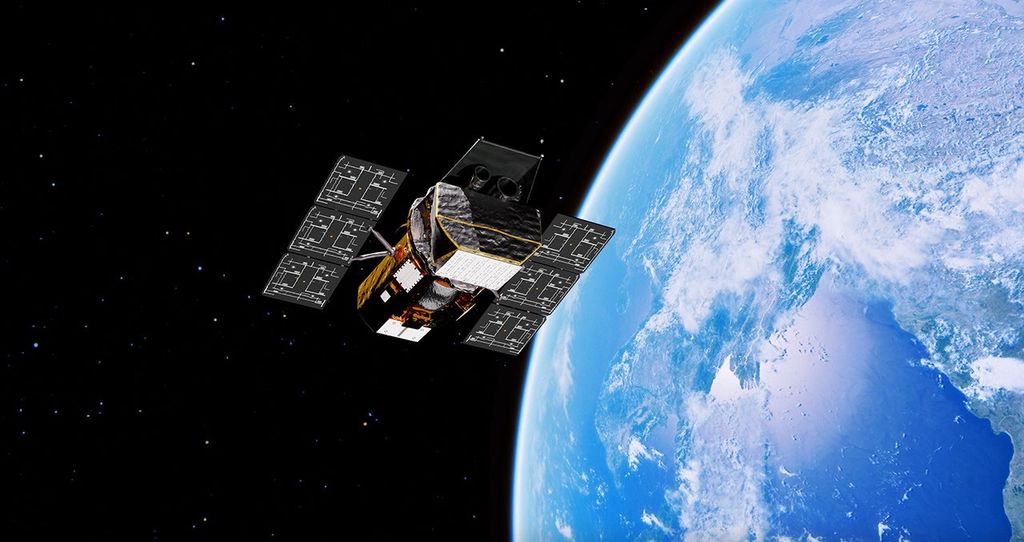
Ku-, K-, and Ka-band communication systems are the state-of-the-art for large spacecraft, especially in spacecraft-to-spacecraft communications, but they are still young technologies in the CubeSat world. They are becoming more attractive to SmallSat designers as the lower frequencies become more congested. At the higher frequencies, rain fade becomes a significant problem for communications between a spacecraft and Earth (1). Nonetheless, the benefits of operating at higher frequencies have justified further research by both industry and government alike. At JPL, the Integrated Solar Array and Reflectarray Antenna (ISARA) mission demonstrated high bandwidth Ka-band CubeSat communications with over 100 Mbps downlink rate (2). The back of the 3U CubeSat was fitted with a high gain reflectarray antenna integrated into an existing solar array. The successful demonstration of the reflectarray on ISARA became the basis for the Mars Cube One (MarCO) mission to Mars. The MarCO mission uses two twin CubeSats for a communications relay between the InSight lander and Earth. Using a X-band reflectarray they were able to successfully complete their mission (3). Another mission to use Ka-band for DTE communications was the Kepler telescope, launched in 2009. With future missions being increasingly data hungry, we are likely to see a shift towards Ka-band and, possibly, even higher frequencies.
CubeSats have also used the unlicensed Industrial, Scientific, and Medical (ISM) bands for communications. The Ames TechEdSat team has successfully demonstrated WiFi to downlink data at 1 Mbps. Notably, a group at Singapore’s Nanyang Technological University used a 2.4 GHz ZigBee radio on its VELOX-I mission to demonstrate commercial-off-the-shelf (COTS) land-based wireless systems for inter-satellite communication (4). Similarly, current investigations are exploring the use of wireless COTS products, such as Bluetooth-compatible hardware, for inter-satellite communications (5).
9.2.2 System Architecture
A small satellite RF communications system consists of a transceiver comprised of a radio, an amplifier, and an antenna. Radios receive a message from the onboard computing subsystem, then produce and modulate an electromagnetic wave to create a signal. They are responsible for generating the signal and modulating or demodulating it. The radio is also where coding may be added to the signal. Channel coding is added to provide data error detection and correction capabilities, which ensures reliable communication under the conditions imposed by the satellite transmission path. From Shannon’s equation (6), it is known that the information capacity of a channel is related to its bandwidth and signal-to-noise ratio (SNR). The channel capacity (information flow) can be increased by increasing the SNR or the bandwidth, and many modulation and coding schemes make effective use of this tradeoff.
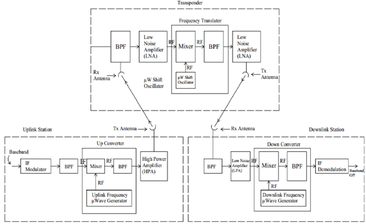
Radios offer some power amplification, but often the signals from small satellites require a greater boost. The power amplifier will take the signal from the radio and increase the RF output power before sending it to the transmit antenna. On the receive side, a low noise amplifier will take the weak signal from the receive antenna and amplify it while minimizing thermal noise. A bandpass filter might be used before the LNA to reject undesired frequencies. The radio will then be able to process the stronger signal with higher accuracy. In RF communications the role of the antenna is to increase and focus the strength of the signal in a specific direction. The digital message encoded on the RF carrier signal will be sent to and from the antennas of each system. See Figure 9.3 for an example transmit and receive block diagram.
9.2.3 Major Components in SmallSat Communication Systems
- Radio or Modulator/Demodulator: on the transmit side, it produces, modulates, codes, and amplifies an electromagnetic wave to create a signal. Adds modulation and coding as needed. As a receiver it decodes and demodulates received signals.
- Mixers: RF mixers are used in communications systems to change the frequency of the signal. If the frequency generated by the radio is not the desired transmit frequency, then an upconverter will convert the signal to a higher frequency for transmit. Similarly, the downconverter will downconvert a receive frequency to a lower one for processing.
- Filters: bandpass filters are used to reject undesired frequencies, typically before the LNA or downconverter.
- Amplifier: a power or gain amplifier is required for a transmit system. A low noise amplifier (LNA) is required for a receive system. LNAs, in addition to amplifying the (low power) received signal, serve to minimize the system noise temperature.
- Antenna: increases the strength of a signal in a specific direction, relative to the same signal strength without directionality. Transmits signals fed to it by a transmitter and receives signals propagated across free space. Antennas can be low-gain and omni-directional with a broad beam, or high-gain & directional with a narrow beam.
- Encryption: a cryptographic unit is an integrated encryptor/decryptor device that provides secure uplink, downlink, or crosslink for satellite communication links. Most small satellite designers will not require a cryptographic payload unit based on their threat level and may be able to use the communications radio for simple encryption schemes.
- Spread-spectrum communication applies a known frequency spreading function to the signal, which helps reduce interference from other transmitters, and provides more secure communications; as such, it is often used for multi-way communication networks. For example, the NASA Tracking and Data Relay Satellite (TDRS) multiple-access mode requires spread spectrum signals to support multiple simultaneous communication links.
9.2.4 Design Considerations
As with all spacecraft subsystems, there are power and mass constraints placed on the communications system. Based on these restrictions, several trade studies need to be performed to choose the optimal design. When designing an RF communications system, the first trades performed are for data rate, power consumption, and total mass. For example, a mission with high data rate needs would select a high frequency such as X-band for downlink and a directional high-gain antenna. Based on the ground station locations available, engineers would perform link budget analyses to determine the minimum power needed for a specific ground station antenna. This analysis would factor in rain and atmospheric attenuation, as well as modulation and coding. A few different link budget trades will be run, varying antenna size, RF output power and data rate. Each link will return a different margin of decibels, representing the reliability of the system. The engineers will proceed to calculate the final mass and power for each configuration. The mission designer will have a limit on mass and power constraints for the communications subsystem. Each configuration traded will compare data rate, power, and mass. A high data rate downlink may cost a high amount of mass for the antenna and power for the amplifier and radio. Conversely, a low-power, low-mass system may have a lower data rate.
Another factor that is considered in the design phase is pointing. Depending on the orbit of the satellite and whether the link is uplink/downlink, or crosslink, the system may have a specific pointing requirement. Large satellites frequently use gimbals—platforms that can pivot to point their antennas. The addition of a gimbal will increase the overall mass and power draws of the system. CubeSats frequently trade high-gain antennas for low-gain, omni-directional ones to maintain the link regardless of directionality. CubeSats may also change their attitude to point a body-mounted antenna, rather than use a gimbal.
9.2.5 Policies and Licensing
Any non-Federal U.S. spacecraft with a transmitter must be licensed by the Federal Communications Commission (FCC). The types of RF licenses used by small satellites are: Amateur (FCC Part 97) and Experimental (FCC Part 5) (7). An amateur license type of authorization is limited to hobbyists and non-profit use and comes with many FCC restrictions. Experimental Part 5 licenses are commonly used for university CubeSats and can be granted for a CubeSat operating in the amateur band (a SmallSat or SmallSat constellation can also apply under provisions of Part 25). A spacecraft with any sort of remote sensing capability must contact the National Oceanic and Atmospheric Administration (NOAA) to find out if a NOAA license is required. A NOAA license is not an RF license and conveys no authority for the radiation of RF energy for communication. For government missions the National Telecommunications and Information Administration (NTIA) is the licensing authority.
For amateur licensing, there must be an FCC licensed amateur radio control operator. Downlink telemetry and communications cannot be obscured (encrypted). Use of science gathered via amateur radio downlink for profit (“pecuniary interest”) is prohibited. Frequency “assignment” in the amateur-satellite allocations requires coordination, a process administered by the International Amateur Radio Union (IARU) (8).
In 2018, the FCC adopted a Notice of Proposed Rulemaking to develop a new authorization process tailored specifically to small satellite operations, keeping in mind efficient use of spectrum and mitigation of orbital debris. Small satellites that would qualify for the new rules include those with 10 or lesser number of satellites under a single license. All individual satellites will have to be at least 10 cm or larger in the smallest dimension and weigh less than 180 kg. The maximum in-orbit lifetime of each individual satellite will be six years, including de-orbiting time, and they would have to be deployed under 600 km altitude. Each satellite will have a unique telemetry marker for tracking and will not release any debris (9).
9.2.6 Encryption
Encryption is the process of encoding information to conceal it from outside actors. Small satellites can use a cryptographic unit to encrypt or decrypt data prior to transmission. When data is being prepared for transmission, it is divided into packets. These packets are then scrambled according to the encryption scheme being used. An encryption scheme uses an encryption key generated by an algorithm to encode the data. The authorized receiver of the encrypted data will be able to decrypt the message using the appropriate key. Without the authorized key, decrypting the data will be extremely difficult.
With the increased proliferation of small satellites in low-Earth orbit comes an increase in vulnerabilities. Many SmallSats are comprised of COTS hardware and/or open-source software. While this strategy allows for a more flexible design approach, adversaries can gain insight into the design. Encryption of data in transit helps prevent other actors from commanding satellites or intercepting transmissions.
NASA requires any of its propulsive spacecraft within 2 million kilometers of Earth to protect their command uplink with encryption that is compliant with Level 1 of the Federal Information Processing Standard (FIPS) 140-3 (10). The FCC has also considered requiring encryption on the telemetry, tracking, and command communications as well as mission data for propulsive spacecraft, but decided not to incorporate a specific requirement at this time. A satellite with an amateur license cannot encrypt transmissions in any way and must consist of open information. The eligibility rules are listed in 47 CFR Part 97 (11).
9.2.7 Antennas
Antennas are used for propagating data through free space using electromagnetic waves. RF antennas are typically sized for their respective frequencies. This means that antennas are often chosen or designed specifically for their mission. COTS antennas are available for SmallSats and can be built to order. For missions that don’t have high data rate requirements, a simple patch or monopole antenna with low gain and efficiency will suffice. Due to their low directionality, these antennas can generally maintain a communication link even when the spacecraft is tumbling, which is advantageous for CubeSats lacking good attitude and accurate pointing control. New developments in antenna design have put technologies like the deployable reflector antenna, reflectarray, and passive or active array antennas on the horizon for small satellites. Please see Table 9-2 for information on commercially available antennas for SmallSats/CubeSats.

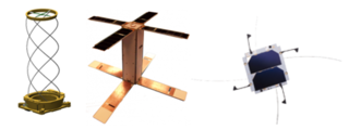
There are two primary classifications of antenna: fixed or deployable. Fixed antennas do not require any power or triggering mechanisms. They remain stationary in the position that they are attached to the spacecraft. This includes patch antennas, array antennas, monopole antennas, omni-directional antennas, and horn antennas (see Figure 9.4). Deployable antennas require power to deploy and use mechanisms to configure into their final position. This includes whip antennas, parabolic reflectors, reflectarrays, helical and turnstile antennas (see Figure 9.5).
A communications link is often characterized by the frequency and data rate. The antenna is a key design decision for meeting data rate objectives by increasing link margin. Increasing the aperture or diameter of an antenna increases the link margin, which can allow designers to increase the data rate of the system or reduce the necessary transmit power.
9.2.8 Radios
Radios for SmallSat downlink are transceivers (transmitter and receiver in one). Transceivers convert digital information into an analog RF signal using a variety of modulation and coding schemes. Radios for TT&C are designed for low data rates, with high reliability and only need to transmit health data and receive commands. Traditional radios may be locked to a single frequency band and modulation/coding scheme based on their design and build. Software-defined radios (SDR) have some or all the radio’s functions implemented in digital signal processing (DSP) software rather than hardware, Figure 9.6. Furthermore, spacecraft teams can change such characteristics on-orbit by uploading new settings from the ground. By using Field Programmable Gate Arrays (FPGAs), SDRs have great flexibility that allows them to be used with multiple bands, filtering, adaptive modulation, and coding schemes, without much (if any) change to hardware (12). SDRs are especially attractive for use on CubeSats, as they are becoming increasingly small and efficient as electronics become smaller and require less power. NASA has been operating the Space Communications and Navigation (SCaN) Testbed on the International Space Station since 2012 for the purpose of SDR TRL advancement, among other things (13). Many radios can provide RF output power to the antenna directly. For higher power applications, an external RF amplifier or high gain antenna may be used. See Table 9-3 for information on commercially available radios for SmallSat/CubeSats.
This report recommends efficient modulation and coding schemes for spacecraft power and bandwidth to increase the data rate and meet bandwidth constraints with the limited power and mass for CubeSat spacecraft. Advanced coding, such as the Consultative Committee for Space Data Systems (CCSDS) low-density parity-check code (LDPC) family, with various code rates, is a powerful technique to provide bandwidth and power with high-order modulation to achieve high data rate requirements for CubeSat missions. Digital Video Broadcast Satellite Second Generation (DVB-S2), a significant satellite communications standard, is a family of modulations and codes for maximizing data rates and minimizing bandwidth use. DVB-S2 uses power and bandwidth efficient modulation and coding techniques to deliver performance approaching theoretical limits of RF channels. NASA’s NSN has conducted testing at NASA Wallops Flight Facility (WFF) to successfully demonstrate DVB-S2 over a S-band 5 MHz channel achieving 15 Mbps with 16 APSK LDPC 9/10 code (14).
| Table 9-2: Antennas | ||||||||||
|---|---|---|---|---|---|---|---|---|---|---|
| Manufacturer | Product | Type | Min Frequency | Frequency Band | Gain | Polarization | Mass | Dimensions | Flight Heritage | |
| — | — | — | [MHz] | — | [dBi] | — | [g] | [cm] | — | |
| MMA Design | LAMBDA | Deployable Sinuous Antenna | 100 | UHF | >-1 | Dual CP | 4000 | 20x15x10 (stowed) 100×100 (deployed) | N | |
| Oxford Space Systems | Helical antenna (high RF power handling) | Deployable | 118-127/127-137 | VHF | >2.5 (isoflux) | LHCP | <1400 | 40x35x34.5 | Y | |
| 2NDSpace | CHORUS-01 LP | Dual Dipole | 140 – 930 | 20 | 0 | 2x Linear | 90 | 10x10x0.8 | Y | |
| 2NDSpace | CHORUS-01 LP | Turnstile | 140 – 930 | 20 | 0 | Circular | 90 | 10x10x0.8 | Y | |
| Oxford Space Systems | Yagi antenna | Deployable | 156.5-162.5 | VHF | >6.5 | Dual Linear | <1000 | 92.5 x 50 (deployed) | Y | |
| Spacemanic | Small Antenna Module | Dipole Cross Dipole | 145 400 435 | VHF, UHF | 2.1 | Linear/ RHCP | 55 | 9.8X9.8X0.56 | Y | |
| Haigh-Farr, Inc. | Part Number: 17100 | Crossed Dipole | 307 | VHF, UHF | — | RHCP | 267 | 32x8x1 | Y | |
| Anteral | 2211-301-01 | Monopole antenna | 400 | UHF | — | Single linear polarized | — | — | Y | |
| GomSpace | NanoCom ANT430 | Omni Canted Turnstile | 400-435 | VHF, UHF | 1.5 | Circular | 30 | 10×10 | Y | |
| Helical Communications Technologies | Helios Deployable Antenna | Helical | 400-3000 | VHF, S | 3 | Circular | 180 | 10x10x3.5 | Y | |
| NanoAvionics | CubeSat UHF Antenna System 1x1U | Turnstile | 400-500 | UHF | 1.37 | — | 33 | 10x10x0.7 | Y | |
| NanoAvionics | CubeSat UHF Antenna System 1x2U | Turnstile | 400-500 | UHF | 2.31 | — | 50 | 20x10x0.7 | Y | |
| NanoAvionics | CubeSat UHF Antenna System 2x2U | Turnstile | 400-500 | UHF | 3.4 | — | 65 | 20x20x0.7 | Y | |
| EnduroSat | UHF Antenna IU | Whip/Burn-wire | 435-438, 400-403 | UHF, VHF | > 0 | RHCP | 85 | 10×10 | Y | |
| EnduroSat | UHF Antenna 2U | Whip/Burn-wire | 435-438, 400-403 | UHF, VHF | > 0 | Linear | 210 | 22.5×9.9x 1.4 | Y | |
| SENyT | UHF antenna | Deployable turnstile | 430-440 | UHF | 0 | Circular | < 150 | 10x10x3 folded | N | |
| ISISPACE | CubeSat Antenna System for 1U/3U | Tape | — | VHF, UHF | 0 | Circular, Linear | 89 | 10x10x0.7 | Y | |
| Flexitech Aerospace | 600MHz – 10GHz Spiral Antenna | Spiral | 600-10000 | UHF, L, S, C, X | 3 | Circular | 1283 | 17x17x8.5 | N | |
| Oxford Space Systems | Helical antenna | Deployable | 862–928 | UHF | > 6.5-7.5 | RHCP | <235 | 30 (deployed helical length) | Y | |
| CesiumAstro | Vireo L-Band Phased Array | APA | 960 | L | 22 | Circular | 49100 | 114x100x13.5 | N | |
| Anteral | 2211-119-03 L2-Band DCP | 2-port dual-circular-polarized (DCP) patch antenna | 1200-1300 | L | 5.8 | RHCP & LHCP | 150 | 9.6×9.6×0.7 (excluding connector) | N | |
| SENyT | Dual-band GNSS antenna | Patch | 1215-1240 1560-1590 | L | 4.5 | RHCP | < 100 | 10x10x0.35 | N | |
| EnduroSat | GNSS Patch Antenna L1+L2 | Patch | 1227.60 1575.42 | L | 3.3+ | RHCP | 114 | 8.3×9.8×0.8 | N | |
| Anteral | 2211-119-02 L1-Band DCP | 2-port DCP patch antenna | 1550-1600 | L | 6 | RHCP & LHCP | 150 | 9.6×9.6×0.7 (excluding connector) | N | |
| EnduroSat | GNSS Patch Antenna L1/E1 | Patch | 1559–1591 | L | 3.6+ | RHCP | 17 | 8.3 x 9.8 x 0.8 | Y | |
| SkyFox Labs | piPATCH-L1E1 | Patch | 1575.42 | GPS-L1 GALILEO E1 | — | — | 50 | 9.8×9.8×1.3 | Y | |
| NAL Research Corporation | Antenna SYN7391-A/B/C (Iridium) | Flat Mount | 1610-1626.5 | L | 4.9 | RHCP | 31 | 4.6x.4.3×1.0 | Y | |
| Oxford Space Systems | Helical antenna (high RF power handling) | Deployable | 1980-2200 | S | >4.0-4.5 | RHCP | <1200 | 60 (deployed helical length) | Y | |
| IQ spacecom | S-Band Single Patch Antenna | Patch | 1980-2500 | S | 6 | Circular | 49 | 7x7x0.34 | Y | |
| IQ spacecom | S-Band Dual Patch Antenna | Patch | 1980-2500 | S | 6 | Circular | 62 | 8x10x0.34 | Y | |
| IQ spacecom | S-Band High Gain Patch Antenna | Patch | 1980-2500 | S | 11.5 | Circular | 179 | 16x16x0.34 | Y | |
| Flexitech Aerospace | 2-2.5GHz Turnstile Antenna | Turnstile | 2000-2500 | S | 5 | Circular | 173 | — | N | |
| SkyLabs | S-band Patch Antenna | Patch | 2025-2110 | S | 6 | LHPC/RHPC | 70 | 8.2×8.2×1.1 | Y | |
| Vulcan Wireless | ANT-S/S Unified S-Band Antenna | Patch | 2025-2300 | S | 6.5 | Circular | 76 | 8x8x1 | Y | |
| EnduroSat | S-band Antenna Commercial | Patch | 2025-2110 | S | 7 | Selectable Circular | 81 | 9.8×9.8×0.6 | Y | |
| Anteral | 2211-114-02 Telecommand DCP | Patch | 2000-2150 | S | 6 | RHCP & LHCP | 150 | 9.6×9.6×0.7 (excluding connector) | N | |
| EnduroSat | S-band Antenna Wideband | Patch | 2025-2110 2200-2290 | S | 5 | RHCP | 115 | 9.8×9.8×0.7 | Y | |
| SENyT | Dual-band S-band antenna | Patch | 2050-2115 2215-2275 | S | 6.5 | LHCP | < 100 | 10x10x0.35 | N | |
| ANYWAVES | S-Band TT&C Antenna | Patch | 2025-2290 | S | 6.5 | RHCP/LHCP | 132 | 8x8x1.2 | Y | |
| Haigh-Farr, Inc. | P/N 21060 | Waveguide | 2020-2120 | S | 25 | LHCP | 667 | 10x10x4.1 | N | |
| ISISPACE | S-Band Patch Antenna | Patch | 2200-2290 | S | 6.5 | RHCP | 50 | 8x8x1 | N | |
| CesiumAstro | Nightingale AAA-2SF1 | Patch | 2025 2200 | S | 5 | RHCP LHCP | 480 | 12×9.5×5 | Y | |
| AeroSpace Lab | SBA-TX | Patch | 2200–2290 | S | 6.1 dBic | RHCP | 118 | 9.5×9.5×2.4 | Y | |
| AeroSpace Lab | SBA – RX | Patch | 2025–2110 | S | 6.1 dBic | CP | 117 | 9.5×9.5×2.4 | Y | |
| Satlab | SAS-2 | Patch | 2025-2110 2200-2290 | S | 6.1 | RHCP | 107 | 10×8.0x0.68 | Y | |
| Anteral | 2211-113-2 SCP | Patch | 2042-2092 2220-2270 | S | 5.5 | RHCP | 129g | 9.9×9.9×0.65 (excluding connector) | Y | |
| Anteral | 2211-114-01 TTC DCP | Patch | 2025-2290 | S | 6 | RHCP & LHCP | 150 | 9.6×9.6×0.67 (excluding connector) | N | |
| Anteral | 2211-113-01 SCP | Patch | 2000-2300 | S | 7 | RHCP | 196 | 9.7×9.7×3.6 | Y | |
| Anteral | 2211-114-03 Telemetry DCP | Patch | 2170-2320 | S | 6 | RHCP & LHCP | 150 | 9.6×9.6×0.7 (excluding connector) | N | |
| Haigh-Farr, Inc. | S-band Patch Antenna | Patch | 2245-2245 | S | — | RHCP | 48 | 4.8×6.5×6.5 | Y | |
| EnduroSat | S-band Antenna ISM | Patch | 2400-2450 | S | 8.3 | LHCP | 64 | 9.8×9.8×0.6 | Y | |
| SENyT | S-band antenna | Patch | 2400-2450 | S | 3.5 | LHCP | <80 | 5x5x0.5 | N | |
| Anteral | 2211-114-05 ISM DCP | Patch | 2400-2450 | S | 6.5 | RHCP & LHCP | 150 | 9.6×9.6×0.7 (excluding connector) | N | |
| Oxford Space Systems | Offset Reflector Antenna (muti feed) | Deployable | 5030-5500 | C | >41 | Linear | <27200 | 350 (deployed reflector diameter, scalable to 600) | N | |
| IQ spacecom | X-Band Single Patch Antenna | Patch | 7145-7250 8025-8400 | X | 6 | Circular | 10 | 3.5×3.5×0.18 | Y | |
| IQ spacecom | X-Band High Gain Antenna | Patch | 7145-7250 8025-8400 | X | 10 | Circular | 12 | 4x6x0.18 | Y | |
| Oxford Space Systems | “Hinged Rib” Cassegrain Antenna | Deployable | 17500-20200 27500-30000 | K/Ka | > 38/41 | Dual Circular (2 channels for Tx & Rx) | < 2500 | 60 (deployed reflector diameter, scalable to 150) | N | |
| Anteral | 2211-128-22 X-Band SCP | Patch | 7900-8500 | X | 12 | RHCP/LHCP | 100 | 5.5×5.5×0.65 (excluding connector) | N | |
| Anteral | 2211-128-44 X-Band SCP | Patch | 7900-8500 | X | >18 | RHCP | 127 | 9.9×9.9×0.65 (excluding connector) | Y | |
| Anteral | 2211-128-UPL-R-8×8-01 X-Band 8×8 Array | Patch | 7900-8500 | X | 22 | RHCP/LHCP | 500 | 22x22x0.52 (excluding fixings and connector) | N | |
| Anteral | 2211-205-03 X band | Waveguide antenna | 8000-10500 | X | 15-17 | RHCP & LHCP | 450 | 9.74×9.9×17.6 | Y | |
| PICOSATS | BEAMSAT X band 4 x 4 patch antenna | Patch | 8000 – 8500 | X | >16 | RHCP | 125 | 98x98x10.8 | N | |
| EnduroSat | X-band Patch Antenna | Patch | 8025-8400 | X | 6 | RHCP | 2.2 | 2.4×2.4×0.2 | Y | |
| EnduroSat | X-band 2×2 Patch Antenna | Patch | 8025-8400 | X | 12 | RHCP | 23.2 | 6.0×6.0x0.3 | Y | |
| EnduroSat | X-band 4×4 Patch Antenna | Patch | 8025-8400 | X | 16 | RHCP | 53 | 9.8×8.3×0.3 | Y | |
| EnduroSat | X-Band 8×12 Patch Antenna | Patch | 8025 – 8400 | X | 26 | RHCP | 490 | 25.4 x 17.2 x 0.7 | N | |
| ANYWAVES | X-band Payload Telemetry Antenna | Patch | 8025-8400 | X | 11.5 | Circular | 65 | 7.3×7.3×11 | Y | |
| MMA Design | T-DaHGR | Deployable Reflectarray | 8400 -10000 | X | 29 – 42.5 | Configurable | 1300 to 11000 | 10x10x10 – 20x20x20 (stowed) Ø70-Ø200 (deployed) | N | |
| MMA Design | NeuSAR | Deployable Reflectarray | 10000 | X | >45.5 | V+H Linear | 16550 | 52x52x25 (stowed) Ø300 deployed | Y | |
| Anteral | 2211-133-DWL-L-44-02 Ku-Downlink 4×4 Array | single-port right-handed-circular-polarized patch antenna | 10700 -11700 | Ku | 17 | RHCP & LHCP | 120 | 9.9 x 9.9 x 0.61 mm (excluding connector) | N | |
| PICOSATS | BEAMSAT Ku band horn antenna | Horn antenna | 10700-12750, 12750-14800 | Ku | >15 >16 | Linear | 633 | 109.1×109.1×205.3 | N | |
| Anteral | 2211-212 Ku band | 4-port DCP dual-band waveguide antenna | 10700-12700 13750-14800 | Ku | 17 | RHCP & LHCP | 700 | 8.9 x 10.2 x 22.1 | N | |
| Anteral | 2211-133-UPL-R-44-01 Ku-Uplink 4×4 Array | single-port right-handed-circular-polarized patch antenna | 14000-14500 | Ku | 26 | RHCP & LHCP | 120 | 0.99×0.99×0.061 (excluding connector) | N | |
| EnduroSat | K-band Patch Antenna | Patch | 17700-20200 | K | 18 | RHCP | 76 | 6.5×6.5×1 | N | |
| PICOSATS | BEAMSAT K band 8 x 8 patch antenna | Patch antenna | 17300 – 21200 | K | >20 | LHCP | 135 | 94.5×94.5×14 | N | |
| Anteral | 2211-138-8×8 – K-Band 8×8 Array | single-port right-handed-circular-polarized patch antenna | 17800-20200 | K | 22.5 | RHCP/LHCP | 120 | 10x10x0.61 (excluding connector) | N | |
| PICOSATS | BEAMSAT K/Ka band horn antenna | Horn antenna | 17300 – 21200, 27000 – 31000 | K/Ka | >19.6, >23.75 | LHCP RHCP | 570 | 88×88.8×218 | Y | |
| Anteral | 2211-218 | Waveguide antenna | 17300 – 21200, 27000 – 31000 | K/Ka | >21 | LHCP & RHCP | 620 | 10.2×10.2×19.7 | Y | |
| PICOSATS | BEAMSAT Ka band 8 x 8 patch antenna | Patch antenna | 27000 – 31000 | Ka | >20 | RHCP | 76 | 78x78x13.5 | N | |
| CesiumAstro | APA-1AT1 | APA | 24500 | Ka | 26.5 | RHCP or LHCP | 500 | 18x18x2 | Y | |
| CesiumAstro | Vireo Ka 288 Tx DRA | APA | 20200 | Ka | 28 | Circular, switchable on orbit | 14500 | 27x23x16 | N | |
| CesiumAstro | Vireo Ka 576 Tx DRA | APA | 17000 | Ka | 31 | RHCP or LHCP, switchable on orbit | 26000-34000 | 40x 40×26.5 | N | |
| CesiumAstro | Vireo Ka 288 Rx DRA | APA | 30000 | Ka | 28 | Circular, switchable on orbit | 7000 | 18×15.5×15.5 | N | |
| CesiumAstro | Vireo Ka 576 Rx DRA | APA | 27000 | Ka | 31 | RHCP or LHCP, switchable on orbit | 23000 to 29500 | 40x40x26.5 | N | |
| Anteral | 2211-250 EO | 2-port DCP waveguide antenna | 25500-27000 | Ka | 30 | RHCP & LHCP | 1000 | 20x20x20 | N | |
| Anteral | DCPCRS-500-40-EO | 2-port dual-DCP cassegrain reflector antenna | 31500-32500 | Ka | 40 | RHCP & LHCP | 2500 | 52.4 x52.4 x 25.5 | N | |
| PICOSATS | BEAMSAT horn antenna | Horn antenna | 37500 – 43500 | Q | >20 | RHCP & LHCP | 150 | 49x49x110 | N | |
| PICOSATS | BEAMSAT horn antenna | Horn antenna | 37500 – 43500, 47500 – 52500 | QV | >30 | RHCP & LHCP | 250 | 119x119x65 | N | |
| Anteral | 2211-229 | Waveguide antenna | 37500-52400 | QV | 30.5 | RHCP & LHCP | 280 | 10x10x15.77 | N | |
| PICOSATS | BEAMSAT ADE antenna | ADE antenna | 59000 – 71000 | V | >30 | RHCP & LHCP | 83 | 79.5×79.5×43.4 | N | |
| EnduroSat | W-band Patch Antenna | Patch | 71000-75000 | W | 23-29 | RHCP | 37 | 8.7×8.1×2.0 | N | |
| Anteral | 2211-236 | Waveguide antenna | 71000-86000 | E | 31.5 | RHCP & LHCP | 152 | 7.5×7.5×9 | N | |
| Table 9-3: Radios | |||||||||||
|---|---|---|---|---|---|---|---|---|---|---|---|
| Manufacturer | Product | Type | Min Frequency | Frequency Band | Data Rate | Tx Power | Mass | Dimensions | Flight Heritage | ||
| — | — | — | [MHz] | — | [kbps] | — | [g] | [cm] | — | ||
| Aerospace Lab | SSDR | SDR | 6 | S | 1840 | 29 dBm RMS | 575 | 12.6×11.1×5.3 | Y | ||
| Vulcan Wireless | NSR-SDR | Radio | 20.100-21200, 30000-31000 | K/Ka | 200,000 | 5W | 615 | 18.3×9.2×3.6 | N | ||
| Aerospacelab | XSDR | SDR | 58 | X | 206,000 | 29 dBm RMS | 555 | 12.6×11.1×5.3 | Y | ||
| Space Micro | MicroSDR-C | SDR | 70-3000 | VHF, UHF, L, S, C | 42,000 | 0 | 750 | 10x10x8 | Y | ||
| Rincon Research | ASTROSDR | SDR | 70-6000 | VHF, UHF, L, S, C | — | 5 dBm | 95 | 9.0×9.0x1.613 | Y | ||
| GomSpace | NanoCom SDR | SDR | 70-6000 | VHF, UHF, L, S, X | — | — | 271 | 9x9x6.6 | Y | ||
| NI Ettus Research | B205mini | SDR | 70-6000 | VHF, UHF, L, S, X | — | 10 dBm | 24 | 8.3×5.1×8 | Y | ||
| Alén Space | TOTEM | SDR | 70 – 6000 | VHF, UHF, L, S | – | 7 dBm | 130 | 9.33×8.93×1.36 | Y | ||
| Alén Space | TREVO | SDR | 70 – 6000 | VHF, UHF, L, S | – | 7 dBm | <714 | 9.33×8.93×27.88 | Y | ||
| Vulcan Wireless | NSR-SDR-MUOS | Transceiver | 300-320, 360-380 | UHF | 64 | 8W | 450 | 10x10x5.6 | N | ||
| AAC Clyde Space | PULSAR-VUTRX | SDR | — | VHF, UHF | 9.6 | 1.5 W | 100 | 9.6x9x1.6 | Y | ||
| SkyLabs | NANOcomm-2 | Transceiver | 130-470 | VHF, UHF | < 25 | 31 dBm | 110 | 9.5×9.1×1.2 | Y | ||
| AstroDev | Helium-100 | Transceiver | 120-150, 400-450 | VHF, UHF | 38.4 | 3 W | 78 | 9.6x9x1.6 | Y | ||
| AstroDev | Lithium-1 | Transceiver | 130-450 | VHF, UHF | 9.6 | 0.25-4 W | 48 | 1.0×3.3×6.5 | Y | ||
| AstroDev | Beryllium-2 | Transceiver | 130-450 | VHF, UHF | 9.6 | 0.25-4 W | 52 | 1×3.3×6.5 | Y | ||
| GomSpace | NanoCom AX100 | Transceiver | 143-150, 430-440 | VHF, UHF | 0.1-38.4 | 30 dBm | 24.5 | 6.5x4x7 | Y | ||
| Spacemanic | Murgas | Transceiver | 145 400 435 | VHF, UHF | 0.1 – 38.4 9.6 | 30dBm | 25 | 6.7×4.2×0.7 | Y | ||
| LY3H | SatCOM TP0 | FM Repeater | 144-146, 430-440 | VHF, UHF | — | 217 mW | 59 | — | Y | ||
| ISISPACE | TRXVU | Transceiver | 145.8-150.05, 400.15-440 | VHF, UHF | 9.6 | 27 dBm | 75 | 9×9.5×1.5 | Y | ||
| Needronix | Cormorant | Transceiver, DNxD-capable digipeater, Morse beacon | 145 – 220 or 390 – 500 | VHF or UHF | 9.6 | 30 | 22 | 4x7x0.65 | Y | ||
| Emxys | ODALISS TTC | Transceiver | 200 | VHF, UHF | 1.2 | 1 W (31 dBm) | <50 | 8.7×8.7×0.93 | N | ||
| CesiumAstro | SDR-1001 | SDR | 300 | UHF, L, S, C | -5 to 6 | 110 | 5×8.4×1.35 | ||||
| CesiumAstro | SDR-2104 | SDR | 600 | L, S, C, X | -5 to 6 | 900 | 16x10x2.54 | ||||
| CesiumAstro | Nightingale RFPU | SDR | 300, 24500 | UHF, L, S, C, Ka | -5 to 6 | 3500 | 20×14.85×13.4 | ||||
| CeisumAstro | SDR-1001 | SDR | 300 – 6000 | UHF, L, S, C | < 62,500 | – | 100 | 5×8.4×1.3 | N | ||
| AAC Clyde Space | TRX-U | Transceiver | 390-450 | UHF | 19.2 | 2 | 140 | 8.3×5.7×1.6 | Y | ||
| NanoAvionics | SatCOM UHF | Transceiver | 395-440 | VHF, UHF | 2.4-38.4 | 3 W | 7.5 | 5.6×3.3×6.6 | Y | ||
| EnduroSat | UHF Transceiver Type II | Transceiver | 400-403, 430-440 | UHF | ≤ 9.6 | 30 – 33 dBm | 94 | 9.6×9.6×1.1 | Y | ||
| SatRev S.A. | UHF Radio | Transceiver with AES128 encryption | 400-405 | UHF | 0.45 | <2W | 158 | 9.6×9.95×1.565 | Y | ||
| SENyT | Q-COMM | Transceiver | 410-475 2400-2480 | UHF, S | 500 | 27 dBm | < 150 | 9.6×9.0x1.5 w/ enclosure | N | ||
| L3 CommunicationsInc. /SDL | Cadet | SDR | 450 | VHF, UHF | 3,000 | — | 200 | 6.9×7.4×1.34 | Y | ||
| CesiumAstro | Vireo RPU | SDR | 600 | L, S, C, X | -5 to 6 | 5000 | 25x15x20.3 | N | |||
| sci_Zone, Inc. | LinkStar-STX3 | Transmitter | 1610-1625 | L | 0.009 | — | 48 | 8.6×5.3×2.9 | Y | ||
| Qualcomm | GSP-1720 | Transmitter | 1610-1626.5, 2483.5-2500 | L, S | 9.6 | 31 dBm | 60 | 11.9×6.5×1.5 | Y | ||
| NAL Research Corporation | NAL Iridium 9602-LP | Iridium Satellite Tracker | 1616-1626.5 | L | — | 1 W | 136 | 6.9×5.5×2.4 | Y | ||
| Near Space Launch | EyeStar-S4 Iridium | Transceiver | 1618.75 | L | 0.1 | 31.96 dBm | 29 | 6x3x2.1 | Y | ||
| L3Harris | CXS-1000 | Transponder | 1700-2100 | L, S | 20,000 | 1-5 W | 1360 | 10x10x11 | Y | ||
| Tethers Unlimited | SWIFT-SLX | SDR | 1700-2500 | S | 6,000 | 33 dBm | 300 | 9×9.8×3.6 | Y | ||
| Tethers Unlimited | SWIFT-XTS S Transceiver X Transmitter | SDR | 1700-2500, 7000-8500 | S, X | 6,000-25,000 | 34 dBm | 800 | 9×9.8×6 | Y | ||
| AAC Clyde Space | TX-2400 | Transmitter | 2000-2300 | S | 6,000 | 2.5 | 70 | 6.8×3.5×1.5 | Y | ||
| Syrlinks | EWC27 + OPT27-SRX | Transceiver | 2025-2110 | S | 100,000 | 27-33 dBm | 400 | 9×9.6×3.9 | Y | ||
| Dragonfly Aerospace | CTRS | Transceiver | 2200-2290 | S | 150 400 | up to 0.5W | 460 | 120x160x35 | Y | ||
| Vulcan Wireless | NSR-SDR-S/S | Transceiver/Transponder | 2025-2115, 2200-2300 | S | 4,000 | 4W | 375 | 9.2×9.5×3.4 | Y | ||
| Dragonfly Aerospace | CTRS | Transceiver | 2025-2115, 2200-2300 | S | 512 | up to 2W | 1000 | 16x12x3.5 | N | ||
| Vulcan Wireless | NSR-SDR-X/S | Transceiver/Transponder | 2025-2115, 8000-8500 | S, X | 10,000 | 5W | 375 | 9.2×9.5×3.4 | N | ||
| Vulcan Wireless | NSR-SDR-X/S HP | Transceiver/Transponder | 2025-2115, 8000-8500 | S, X | 10,000 | 10 W | 615 | 18.3×9.2×3.6 | N | ||
| Orion Space Solutions | Triton-XST | Transmitter | 2200, 8000 | S, X | <670 Mbps | 25-50 W | 500g | 10x10x10 | N | ||
| CesiumAstro | Vireo RPU | SDR | 17000 27000 | Ka | — | -5 to 6 | 7400 | 25×22.6×20.3 | N | ||
| IQ spacecom | HISPICO | Transmitter | 2100-2500 | S | 1,000 | 27 dBm | 100 | 9.5×4.6×1.5 | Y | ||
| Innoflight, Inc. | SCR-104 | SDR with AES-256 Encryption | 2200-2290 1760-1840 2025-2110 | S L/S | >4,500 1000 | — | 250 – 290 | 8.2×8.2×2.5 9.8×8.2×3.3 | Y | ||
| CUBECOM | STXG2 | Transmitter | 2200-2290 2400-2480 | S | 25,000 | — | 137 | 9.6×9.0x13 | N | ||
| Emhiser Research, Inc. | ETT-01EBA102-00 | Transmitter | 2200-2400 | S | — | 1 W | 57 | 3×8.6×0.8 | Y | ||
| Quasonix | NanoTX | Transmitter | 2200.5-2394.5 | S | 50 | 1-10 W | — | 3.3×8.6×0.8 | Y | ||
| IQ spacecom | SLINK-PHY | Transceiver | 2200-2290, 2025-2110 | S | 64-4000 | 30 dBm | 275 | 6.5×6.5×13.7 | Y | ||
| ISISPACE | TXS | Transceiver | 2200-2290 | S | 4.3 | 27-33 dBm | 132 | 9.8×9.3×1.4 | Y | ||
| Space Inventor | STTC-P3 | SDR | 2200-2290 | S, X | 9 – 10,000 | 33 dBm | 230 | 9.1×9.4×1.7 | Y | ||
| Satlab | SRS-3 | Transceiver | 2200-2290 | S | 512 | 30 dbM | 190 | 8.7×9.3×1.7 | Y | ||
| Satlab | SRS-4 | Transceiver | 2200-2290 | S | – | 33 dbM | 253 | 9.3×8.7×1.75 | Y | ||
| Syrlinks | S-band Transponder | Transponder | 2200–2290 | S | 8-2000 | 27-33 dBm | — | — | Y | ||
| Syrlinks | EWC15-NG | Transceiver | 2025-2110 2200-2290 | S | 512 2,000 | 33 dBm | 1280 | 17.2x12x6.7 | N | ||
| Syrlinks | EWC31 | Transceiver | 2025-2110 2200-2290 | S | 256 2,000 | 33 dBm | 405 | 9.5×9.5×5.3 | Y | ||
| Syrlinks | EWC31-NG | Transceiver | 2025-2110 2200-2290 | S | 512 2,000 | 33 dBm | 360 | 9.5x9x3.2 | N | ||
| EnduroSat | S-band Transceiver II | Transceiver | 2200 – 2290, 2025 – 2110 | S | < 125 | 27-33 dBm | 246 | 9.4×8.8×2.3 | Y | ||
| EnduroSat | S-Band Transceiver III | Transceiver | 2200 – 2290, 2025 – 2110, | S | ≤ 3000 | 27 – 33 dBm | 340 | 9.6×9.6×2.5 | N | ||
| EnduroSat | S-band Transmitter | Transmitter | 2200-2290, 2400-2450 | S | ≤ 20000 | 27 – 33 dBm | 250 | 9.6 x 9.6 x 1.5 | Y | ||
| General Dynamics | S-Band TDRSS/DSN | Transponder | 2200-2300 2025-2220 | S | 12,000 | 0.03 W | 4900 | 19x23x15 | Y | ||
| SkyLabs | NANOlink-S base Gen2 | Transceiver | 2200-2300 | S | < 4000 | 30 dBm | 126 | 9.5×9.1×1.2 | Y | ||
| SkyLabs | NANOlink-S boost Gen2 | Transceiver | 2200-2300 | S | < 4000 | 37 dBm | 250 | 9.5×9.1×2.2 | Y | ||
| SkyLabs | NANOlink-S boost-dp Gen2 | Transceiver | 2200-2300 | S | < 4000 | 31.5 dBm | 391 | 9.5×9.1×3.2 | Y | ||
| Microhard | Nano N2420 | Modem | 2400-2483.5 | S | 230 | 0.1-1 W | 210 | 5x3x0.6 | Y | ||
| Paradigma Technologies | PFES-1 ISL S Band TDD Front End | Transceiver | 2400-2500 | S | – | 25 dBm | 150 | 5.0×3.0x 1.0 | N | ||
| Tethers Unlimited | SWIFT-XTX X Transmitter | SDR | 7000-8500 | X | 25,000 | 33 dBm | 300 | 9×9.8×6 | N | ||
| General Dynamics | X-Band Small Deep Space | Transponder | 7145-7230, 8400-8500 | X | 100,000 | 0.06 | 3200 | 18x17x11 | Y | ||
| Space Dynamics Laboratory | IRIS V2.2 | SDR Transponder | 7145–7235 GHz 8400–8500 GHz | X, Ka, S, or UHF | 0.1 – 10000 | 36 | 875 | 10.1×10.1×5.6 | Y | ||
| Paradigma Technologies | PTX-1 | Transmitter | 7700 – 8500 | X | – | 43.5 dBm | 800 | 12.5x10x3.0 | N | ||
| Innoflight, Inc. | SCR-106 | SDR with AES-256 Encryption | 7800-8500 760-1840 2025-2110 | X L/S | 20,000 1,000 | 0.02-2.5 W | 250 – 290 | 8.2×8.2×2.5 9.8×8.2×2.8 | Y | ||
| Innoflight, Inc. | SCR-108 | SDR with AES-256 Encryption | 19200-21200 29000- 31000 | Ka Ka | 1 Gbps 20,000 | 0.02-3 W | 404 | 9.8×8.7×3.9 | Y | ||
| EnduroSat | X-band Transmitter | Transmitter | 7900-8400 | X | ≤1.5 Gbps | 27-33 dBm | 270 | 9.6×9.6×2.6 | Y | ||
| Dragonfly Aerospace | HDRTX-1.5 | Transmitter | 8025-8400 | X | 1.5 Gbps | < 4W | 1600 | 17.5 × 14.5 × 5.5 | Y | ||
| Dragonfly Aerospace | HDRTx-3 | Transmitter | 8025-8400 | X | 3 Gbps | up to 4W | 1600 | 17.5×14.5×5.5 | N | ||
| SkyLabs | NANOcast | Transmitter | 8025-8500 | X | <1 Gbps | 37 dBm | 164 | 9.5×9.1×1.3 | N | ||
| CUBECOM | XTXG2 | Transmitter | 8025-8400 | X | 2.5 Gbps | — | 137 | 9.6×9.0x1.3 | N | ||
| CUBECOM | µHDTRX-X | Transmitter | 8025-8400 | X | 1.5 Gbps | — | 250 | 9.6×9.0x2.0 | Y | ||
| CUBECOM | HDRTX | Transmitter | 8025-8400 | X | 1 Gbps | — | 250 | 9.6×9.0x2.0 | Y | ||
| Satlab | SRX-8 | Transmitter | 8024-8400 | X | <1 Gbps | 33 dBm | 300 | 9.3×8.7×2.2 | Y | ||
| IQ spacecom | XLINK | Transceiver | 8025-8500, 7145-7250 | X | 64-25,000 | 30 dBm | — | <1 U | Y | ||
| SkyLabs | NANOcast | Transmitter | 8025-8500 | X | < 1 Gbps | 37 dBm | 164 | 9.5×9.1×1.3 | N | ||
| Syrlinks | EWC27 | Transmitter | 8025-8500 | X | 1.4 Gbps | 27-33 dBm | 235 | 9×9.6×2.6 | Y | ||
| Syrlinks | EWC27 + OPT27-SRX | Transceiver | 2025-2110 8025-8500 | S, X | 256 1 Gbps | 33 dBm | 320 | 9.6x9x3.9 | Y | ||
| Syrlinks | N-XONOS | Transmitter | 2025-2110 8025-8400 | S, X | 256 4 Gbps | 33 dBm | 385 | 9.5x9x3.1 | Y | ||
| Syrlinks | XONOS | Transmitter | 2025-2110 8025-8500 | S, X | 256 6.3 Gbps | 40 dBm | 2400 | 20.6×15.2×6.9 | N | ||
| Argotec | UST-Lite | Transponder | 2025-2120 2200-2300 7145-7235 8400-8500 22550-23550 25500-27500 | S, X, K, Ka | < 1 Gbps (higher possible with NRE) | 8 dBm (input to SSPA) | <4000 (quad-band) | 19.9×14.1×12.1 (quad-band) | N | ||
| Tethers Unlimited | SWIFT-KTX Ka Transmitter | SDR | 20200-21200 24000-27000 | Ka | 25,000 | 33 dBm | 300 | 9×9.8×4 | N | ||
| Tethers Unlimited | SWIFT-KTRX Ka Transmitter | SDR | 24000-27000 | Ka | — | 35 dBm | 1,000 | 16×9.6×6 | N | ||
| SpaceMicro | microKaTx-300 | Transmitter | 25250-27250 | K | 1 Gbps | 2 W | 1000 | 10x10x8 | Y | ||
| AAC Clyde Space | PULSAR-DATA XTX X-Band Transmitter | SDR | — | X | 50,000 | 2 W | 130 | 9.6x9x1.1 | Y | ||
| EnduroSat | X-band SDR | Transmitter | 8000 – 8400 | X | ≤ 6 Gbps | 27 – 33 dBm | <2500 | 9.2 x10x11.5 | Y | ||
| Paradigma Technologies | PTRKU-1 | Transponder / Transceiver | 10700-12700 12750-14000 | Ku | – | 33 dBm | 350 | 9.4×9.4×2.2 | N | ||
| EnduroSat | K-band SDR | Transmitter | 25500-27000 | K | ≤ 2 Gbps | 27 – 33 dBm | <5000 | 9.2x10x15 | N | ||
| AAC Clyde Space | PULSAR-DATA STX | SDR | — | S | 7,500 | 1 W | 100 | 9.6x9x1.7 | Y | ||
| Honeywell | STC-MS03 | Transceiver | — | S | 6,250 | 3.16 W | 1000 | 16x11x4.4 | Y | ||
| Innoflight, Inc. | SCR-106HDR | SDR with AES-256 Encryption | 7800-8500 1760-1840 2025-2110 | X L S | 1 Gbps 20,000 | – | 250 – 290 | 8.2×8.2×2.5 9.8×8.2×2.8 | Y | ||
| EnduroSat | Versatile Wideband SDR (VW-SDR) | Transceiver | 75 – 6000 | VHF, UHF, L, S, C | 982,000 | -10 dBm | <1500 | 9.8×9.8×7.5 | Y | ||
| Trident | RDRT | SDR – RF System on Chip (RFSoC) | 100 | L/S | 8-channels 250MHz, 6554MH, 8-channels 250MHz, 4096MHz | -1 dBm Full-scale | 571 | 10×14.6×2.54 | N | ||
| Trident | ADCM | SDR – MPSoC Basecard and -SP converters – RX only | 100 | L, S, C | 6.4GSPS single channel, 3.2 GSPS dual-channel | 2.8dBm Full scale input | 690 | 10×14.6×2.54 | N | ||
| Space Dynamics Laboratory | Iris Radio V3 | SDR Transponder | Various | Simultaneous Multiband: X, Ka, S | 0.1 – 10000 | 34 | 720 | 10.1×10.1×3.8 | N | ||
| PICOSATS | RADIOSAT | Transponder | 17300 – 21200 27000 – 31000 | K/Ka | – | 5 | 690 | 93.5×114.15x 45.6 | Y | ||
| PICOSATS | RADIOSAT | Transponder | 10700 -12750 12750 -13250 13750 -14800 | Ku | – | 5 | < 1000 | 93.5x 114.2×62.1 | N | ||
| PICOSATS | RADIOSAT | Transceiver | 17300 – 21200 27000 – 31000 | K/Ka | 4 Gbps 1 Gbps | 5 | 900 | 83.50 x 114.15 x 53 | N | ||
| PICOSATS | BEAMSAT | Transceiver | 10700 -12750 12750 -13250 13750 -14800 | Ku | 4 Gbps 1 Gbps | 5 | 1000 | 93.5×114.2×70.6 | N | ||
| PICOSATS | RADIOSAT SDR | Modem/Transceiver (SDR) | 300 – 7000 | UHF, L, S, C | 4 Gbps 1 Gbps | 0,001 | < 500 | 83.5x96x25 | N | ||
| Paradigma Technologies | PEWR-1 Wideband Receiver | Receiver | 100 – 22000 | VHF to Ka | – | 0 dBm | 550 | 20x10x1.5 | N | ||
| Paradigma Technologies | PTRKA-1 | Transponder / Transceiver | 17200 – 21200 27000 – 31000 | K/Ka | – | 33 dBm | 350 | 9.4×9.4×2.2 | Y | ||
| PICOSATS | BEAMSAT | Transmitter | 25500 – 27000 | Ka | 4 Gbps | 5 | 900 | 83.5×114.15×53 | N | ||
| Paradigma Technologies | PTRQV-1 | Transponder / Transceiver | 37500 – 42500 47200 – 52400 | K/Ka | – | 30 dBm | 350 | 9.4×9.4×2.2 | N | ||
| Paradigma Technologies | PTQ-1 | Transmitter | 37500 – 42500 | Q | – | 22 dBm | 350 | 9.4×9.4×2.2 | Y | ||
| Paradigma Technologies | PTRQV-1 | Transponder / Transceiver | 37500 – 42500 47200 – 52400 | QV | – | 30 dBm | 350 | 9.4×9.4×2.2 | N | ||
9.3 Free Space Optical Communications
Free space optical communications, or lasercom, uses optical wavelengths of electromagnetic radiation to transmit messages wirelessly between user terminals. While few small satellite optical communications terminals have flown, availability is improving, and optical communication is becoming a more common wireless communication technology for small satellites.
Due to the higher frequencies of electromagnetic energy used in lasercom, the amount of bandwidth available for communicating is much larger than that available for RF. This increase in bandwidth over RF enables much higher data rates. The beam width of a lasercom link is also typically much narrower than that of the RF link (displayed in Figure 9.7). The amount that a transmitted beam spreads as a function of its propagation distance is called its divergence. The divergence of a beam is proportional to the wavelength of the electromagnetic wave transmitted divided by the transmitted beam diameter. The high frequencies used in lasercom mean that the wavelength of the transmitted energy is orders of magnitude smaller than RF systems. These small wavelengths mean that the transmitter diameters and beam divergence of lasercom systems can also be much smaller, which enables the size, weight, and power (SWaP) of lasercom systems to be lower than those of similarly performing RF systems. Laser communications have a low probability of intercept, are difficult to jam, and encounter very little interference because of the narrow beamwidth. At present, optical frequencies are unregulated, unlike RF systems that require a licensing process to be able to communicate with a spacecraft.

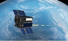
Lasercom is not without its disadvantages, which include the required beam pointing accuracy and the impact that weather has on the signal. The small beam divergence of lasercom transmit beams means that the acceptable pointing error of the narrow beam is much smaller than that of typical RF systems. The frequencies used in lasercom systems are also susceptible to large amounts of attenuation due to moisture in clouds. This attenuation prohibits communication while there is cloud cover and incentivizes operators to build their optical ground stations in areas with infrequent cloud cover. While larger missions such as the Geosynchronous Lightweight Technology Experiment (GeoLITE), Near Field Infrared Experiment (NFIRE), and Lunar Laser Communication Demonstration (LLCD) demonstrated laser communications downlinks and crosslinks decades ago, SmallSats and CubeSats have successfully demonstrated laser communication downlinks from space. For example, The Aerospace Corporation, in cooperation with NASA ARC, launched three CubeSats in its AeroCube Optical Communication and Sensor Demonstration (OCSD) series (Figure 9.8). OCSD-B and C demonstrated a 200 Mbps downlink from a 1.5U CubeSat to a 40 cm ground station (16). The Aerospace Corporation transmitter has also successfully flown on follow-on missions that were able to use lasercom systems to downlink science data (17).
9.3.1 System Architecture
An optical modem, optical amplifier, and optical head typically comprise a lasercom terminal (LCT) (see Figure 9.9 for an example system diagram of an optical head). As with radio terminals, component locations in optical terminals can vary; for example, the modulator may not be located near the optical front end. Also, the pointing mechanism might differ from the one shown in Figure 9.9.

The key parameters of an optical communication system are frequency, modulation, aperture size, and range. Successful optical communications links require high pointing accuracy. The optical communication terminal on a spacecraft typically has a two-stage pointing system, with a coarse-pointing stage and a fine-pointing stage. The optical communication system often relies heavily on the spacecraft attitude determination and control system (ADCS) for coarse pointing and may use a second pointing mechanism such as a gimbal as additional support for coarse pointing. Fine pointing is often implemented with additional mirrors in the payload. However, pointing that is solely dependent on spacecraft attitude control has also been demonstrated. On transmit, energy passing through the optical aperture forms a very narrow beam. The larger the aperture, the narrower the beam; this creates higher power density at a receiver for a given range, but comes at the expense of more demanding pointing requirements for the transmit beam.
For two communication terminals to locate each other, they may shine higher-power and broader-beam “beacon” lasers to find each other before engaging the narrower and higher data rate link. Other strategies are possible, for example, scanning the direction of the data beam until acquisition is achieved. The beacon itself may also be modulated. Optical modems may be software-defined and can support multiple modulation and coding schemes, similar to RF.
9.3.2 Optical Ground Stations
The ground stations for optical communications understandably differ significantly from RF ground stations due to the need for the receiving aperture (typically a mirrored telescope) to maintain an optical-quality surface to focus the collected optical energy onto a receiver. Optical ground stations are often located at or near astronomical telescope sites, as they are located in favorable “seeing” environments, that is, locations with a low chance of cloud cover and calm, non-turbulent air.Optical ground stations are typically mounted inside protected domes or other structures to cover them during bad weather. These structures typically need to be opened for clear access to the sky. Since optical ground stations often have beacons, it is important to consider laser safety and their proximity to airports. Typical ground-to-space beacons are on the order of tens of watts of optical power for low-Earth orbit missions. Most optical ground stations are experimental facilities used for campaigns with specific research missions, although there have been recent developments in commercial optical ground stations. For a more detailed descriptions of existing optical ground stations, refer to the Ground Data Systems and Mission Operations chapter.
9.3.3 Design Considerations
Lasercom terminals can offer a smaller footprint and lower power draw compared to those of an RF terminal. However, lasercom pointing requirements are significantly more demanding. One of the largest challenges to widespread implementation is the pointing accuracy required for the LCT. To manage the pointing challenges, there are different types of system implementation and components that can be used, depending on resource constraints, performance requirements, and mission lifetime. The LCTs that have been designed, built, and operated on small satellite and CubeSat platforms have some significant differences from LCTs designed for larger spacecraft. Given the size, weight, and power constraints for SmallSat LCTs, mechanical gimbals are typically not used. SmallSat lasercom systems may rely entirely on the body pointing of the satellite to point the LCT at the ground station, or they may use an internal fine pointing mechanism to achieve the required fine-pointing performance.
On SmallSat platforms, the limited volume and tight packaging is often a major challenge in the design of low-SWaP LCTs. There are thermal management challenges during operation, as it is difficult to radiate enough heat given the limited surface area for radiators. There are also power constraints due to limited surface area for solar arrays and secondary battery systems. In addition, not all SmallSat platforms can achieve the pointing requirements necessary for laser communications. Typically, both precise three-axis reaction wheels for actuation and attitude determination sensing from at least one star tracker are necessary.
While RF bands with high frequency and bandwidth are also affected by clouds and rain, cloud cover can prove difficult or even insurmountable for optical communications systems due to the high levels of attenuation. If the cloud coverage is too great at a specific ground station, the transmission may be held for a later time or passed off to a different ground station. With advances in intersatellite networking and the development of extensive networks of optical communication ground stations, routing data around weather may become more feasible.
The atmosphere is also a source of aberrations for optical communication systems, particularly for terminals with larger apertures and more complex receivers designed to support higher data rates. For example, some high-rate optical downlink terminals that require coupling the received light into fiber receivers must use adaptive optics to correct atmospheric effects on the incident wavefront. Without correction of the wavefront, there would be a lack of received signal power to couple into the receive optical fiber due to the perturbed wavefront of the received light. Adaptive optics systems take a sample of the incident wavefront before it reaches the receiver and measure the aberrations of the wavefront to provide input to the control of the adaptive optics system that acts on the received light and counters the aberrations.
Lasercom crosslinks can provide a high bandwidth connection between two satellites, as well as perform ranging between the satellites, potentially with high ranging precision. Connecting two satellites across different orbit planes can help with data routing and can reduce how long it takes to route data to the end user. Lasercom crosslink systems are now in use for both commercial and government missions. Lasercom crosslink demonstrations have been performed from GEO-LEO, LEO-GEO, LEO-LEO, and are operational as part of the European Data Relay Service (43)(44), but these LCTs were developed for much larger spacecraft (20)(21). Crosslinks also have the challenge of both terminals being resource-constrained onboard a spacecraft. Space-to-ground links have an advantage in that the ground station apertures can be large with essentially unconstrained resources relative to what is available on a satellite. The challenges facing inter-satellite optical communications also center on pointing, acquisition, and tracking (PAT) requirements. Satellites in different orbital planes can have high relative velocities and performing pointing, acquisition, and tracking of the terminal can be a challenge. An advanced opto-mechanical system may be needed to surmount this challenge, and special consideration may be needed in the design of the receive optics to manage high Doppler shifts.
9.3.4 Policies and Licensing
Given the early stages of implementation for satellite optical communication systems, both policy and regulatory approaches are still evolving. In the policy realm, there is an initial draft of the CCSDS Pink Book in process (CCSDS 141.0-P-1.1) with a goal to facilitate interoperability and cross-support between different communication systems. There is also an optical communications working group with NASA and ESA participation. The U.S. government Space Development Agency has also recently released its Optical Communications Terminal (OCT) Standard Version 4.0.0 (28th June 2024), which is a widely used design reference for space lasercom terminals, although not yet targeted specifically to small satellite terminals.
Regarding licensing and regulation, the situation is very different from the radio frequency domain. Currently there are no licensing requirements for laser communications. In the radio frequency spectrum, the main goal for licensing is to prevent interference between transmitters.
Lasercom interference is not currently coordinated by a regulatory body (like the ITU or NTIA in RF), although there have been historical ITU World Radiocommunication Conference resolutions that have considered implementing regulations. There is currently no regulation for two major reasons:
- Laser communications is highly directional, which makes interference unlikely, due to the narrow divergence of the transmitting beam and corresponding small beam footprint at the receiver.
- The small number of organizations that deploy laser communication systems doesn’t warrant a complex coordination body like the ITU.
However, in the U.S. there are three regulatory entities that are concerned with aspects of outdoor laser operations: the FAA, the DoD Laser Clearing House (for DoD missions) and the NASA Laser Safety Review Board (for NASA missions).
FAA coordination is required if potentially harmful laser irradiance is transmitted through navigable airspace. This includes prevention of injury as well as potential distraction of pilots by visible lasers. The FAA will most likely only be concerned about transmitters at ground stations because transmitters on spacecraft are hundreds of miles above the highest-flying aircraft and beam dispersion is large enough that there are usually no safety implications. Missions should coordinate with their local FAA service center to get approval, documented with a “letter of non-objection.”
The DoD Laser Clearinghouse (LCH) works to ensure that DoD and DoD-sponsored outdoor laser use does not impact orbiting spacecraft or their sensors. That includes both US DoD and foreign assets. LCH and mission operators might enter close cooperation where LCH permits specific laser engagements. The process of coordinating with LCH to get to that point can take many months and should be started as early as possible. However, currently LCH will only engage DoD and DOD-sponsored missions.
NASA’s Laser Safety Review Board (LSRB) is focused on personnel safety for all outdoor laser operations. NASA missions prepare safety documentation and submit to LSRB for review before launch. The LSRB will also verify FAA concurrence. Further information on regulations can be found in ANSI Z136.6, American National Standard for Safe Use of Lasers Outdoors, and in (45).
9.3.5 Mission Examples
SmallSat and CubeSat missions using lasercom terminals have shown viable pathways for overcoming the challenges associated with lasercom to enable high-bandwidth communications. Please refer to Table 9-4 for more information on lasercom missions. These efforts promote research toward practical applications of space optical communication technologies in the future.
The Small Optical Transponder (SOTA) project led by the National Institute of Information and Communications Technology (NICT) in Japan successfully demonstrated a laser space-to-ground link from a 50 kg microsatellite multiple times between 2014 and 2016 (22). This LCT was capable of up to 10 Mbps; the Very Small Optical Transponder (VSOTA) LCT, also developed by NICT, is capable of 1 Mbps. VSOTA was integrated into the Rapid International Scientific Experiment Satellite (RISESAT) from Tohoku University and launched in 2019 (23). Planned for 2027 is the demonstration of several technologies to enable optical communication constellations.
The German Aerospace Center (DLR) develops LCTs under its Optical Space Infrared Downlink System (OSIRIS) program to support laser downlinks from small satellites, using reference beacons for fine pointing. OSIRISv1 launched in 2017 on the University of Stuttgart’s Flying Laptop satellite, demonstrated 200 Mbps downlinks using a body‑pointing‑only approach and continues to support testing of DLR’s optical ground stations. The OSIRISv2 LCT, launched in 2016 on DLR’s BiROS satellite, provided 1 Gbps and employed closed-loop body pointing with a beacon reference; portions of the terminal have been commissioned to date (24)(25)(26). The OSIRIS4 CubeSat transmitter, demonstrated in 2021, achieved an optical downlink in a 0.3U package using a MEMs fast-steering mirror for fine pointing. Designed to be compatible with a 60 cm optical receiver, this terminal has been commercialized through TESAT with the product name CubeLCT (28). A modified version, CubeISL by DLR, adds a receive optical path and fiber amplifier to support 100 Mbps crosslinks at distances up to 1000 km and 1 Gbps downlinks. The terminal has a mass below 1 kg, a volume of 1U, and an operating power of about 30 W (35). A dedicated on-orbit demonstration of these terminals is planned for 2026 using two 6U CubeSats as host platforms (36).
The Aerospace Corporation completed the first demonstration of optical communications from a 1.5U CubeSat platform with the NASA-sponsored Optical Communication and Sensor Demonstration (OCSD) mission. The terminals achieved a 200 Mbps downlink data rate to a 40 cm ground station and did not use a beacon for a pointing reference (16). This transmitter has been flown since on multiple missions such as R3 (17) and the Rogue Alpha and Beta CubeSats (18). An updated version was later demonstrated on the Slingshot mission, achieving downlink rates at 250 Mbps (19). In 2025, The Aerospace Corporation also demonstrated an optical crosslink between two 6U CubeSats at distances of roughly 560 km using its Flashlight Laser Crosslink Terminal. This terminal occupies approximately two units of volume and supports bidirectional data rates of 312.5 Mbps (46).
MIT Lincoln Laboratory developed the TeraByte InfraRed Delivery (TBIRD) terminal, which achieved 200 Gbps downlinks. The transmitter uses commercial fiber telecommunication transceivers and amplifiers to support very high data rate downlinks. This project used NASA JPL’s Optical Communication Telescope Laboratory (OCTL), which hosts a 1 m telescope with the adaptive optics necessary to couple the received light back into an optical fiber connected to a transceiver for demodulation. This terminal development was sponsored by NASA and was launched on the PDT-3 6U CubeSat mission in June of 2022 (33). It has thus far achieved the transmission of 4.8 Tb in a single pass and has demonstrated the value of implementing an automatic repeat request protocol in the use of lasercom downlinks (31)(32).
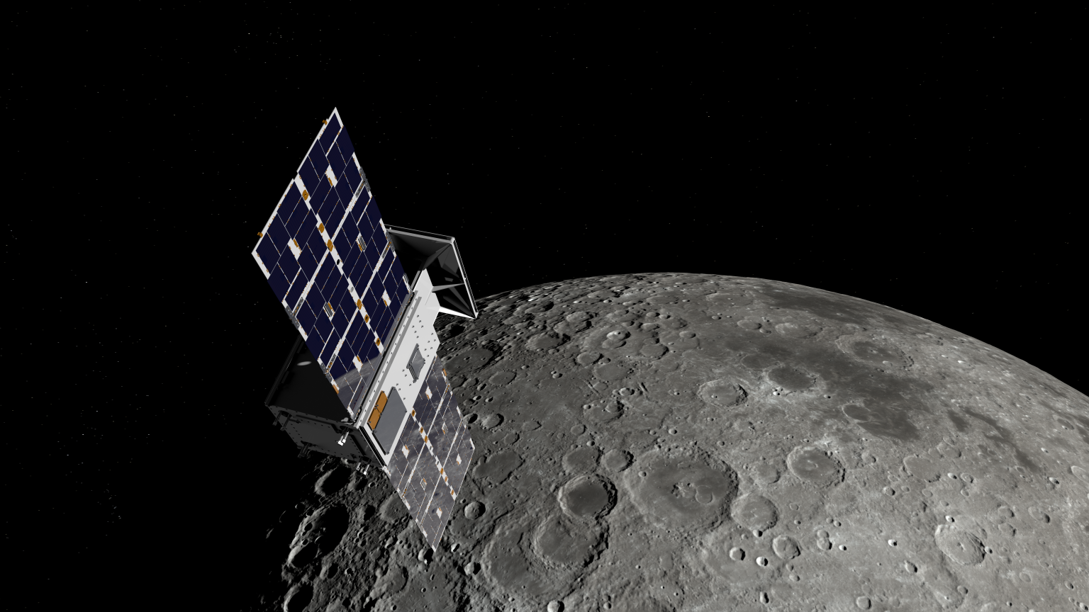
As part of NASA’s CLICK mission, MIT developed the 1.2U CLICK-A terminal. The first phase of the mission flew the CLICK-A downlink terminal on a 3U CubeSat to demonstrate an optical design that uses a secondary fine pointing micro-electromechanical systems (MEMS) fine-steering mirror (FSM) to achieve the necessary pointing requirements for optical communication without imposing those requirements on spacecraft body pointing or needing large gimbals. This LCT uses closed-loop fine pointing with a beacon reference and is designed to close its link with a 28 cm ground station. The terminal was integrated into a Blue Canyon Technology’s XB1 spacecraft bus and was launched to and deployed from the ISS in 2022. The mission successfully demonstrated improved pointing with the MEMS FSM compared to body-only pointing. CLICK-A ultimately served as a risk-reduction phase for the CLICK-B and C mission operations (27).
The CLICK-B/C phase of the CLICK mission is developing a 1.5U crosslink LCT. The CLICK-B/C crosslink LCT is designed to establish a 20 Mbps link at separations from 25 to 580 km. CLICK-B and C will each be integrated into their own 3U Blue Canyon Technologies XB1 spacecraft. The LCTs are designed to be capable of precision ranging up to a precision of 50 cm relative to each other. The spacecraft will be launched to and deployed from the ISS in late 2026 and will fly in the same orbital plane (27).
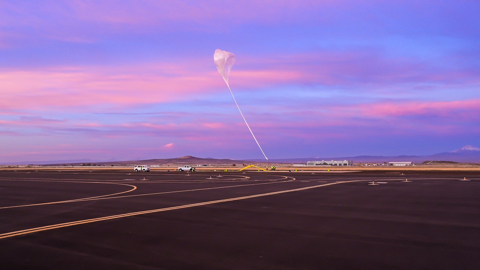
The Laser Crosslink Experiment (LaCE) by Los Alamos National Laboratory consisted of two 6U CubeSats that demonstrated the Skylight Laser Communication Terminal crosslink as their primary objective. The Skylight LCT was designed to actively steer the laser communication payload to establish an optical link between the two CubeSats which it successfully did in 2024 (47)(48). At a distance of 7.4 km between each CubeSat, 2 Tbit/s was achieved in an urban environment with atmospheric turbulence. Future efforts aim to miniaturize the terminals while supporting data rates of up to 10 Gbit/s between a LEO spacecraft and the ground in 2026, and between a satellite and a high-altitude balloon in 2027.
| Table 9-4: LCT Technologies | ||||||||
|---|---|---|---|---|---|---|---|---|
| Vendor / Developer | Terminal | Platform | Data Rate | Mass | Power | Wavelength | Modulation | Launch Date |
| — | — | — | [Mbps] | [kg] | [W] | [nm] | — | — |
| NICT | SOTA | SOCRATES | 10 | 5.9 | 16 | 976/800/1549 | OOK | May 2014 |
| DLR | OSIRISv2 | BiROS | 1000 | 1.65 | 37 | 1550 | OOK | June 2016 |
| DLR | OSIRISv1 | Flying Laptop | 200 | 1.3 | 26 | 1550 | OOK | July 2017 |
| Aerospace Corporation | OCSD-B&C | AeroCube-7 | 200 | <2.3 | 20 | 1064 | OOK | December2017 |
| NICT | VSOTA | RISESAT | 1 | <1 | 4.33 | 980/1550 | OOK/PPM | January 2019 |
| Sony/JAXA | SOLISS | ISS | 100 | 9.8 | 36 | 1550 | OOK | July 2019 |
| DLR | OSIRIS4CubeSat | PIXL-1 | 100 | 0.4 | 10 | 1550 | OOK | January 2021 |
| MIT Lincoln Labs | TBIRD | PDT-3 | 200,000 | <3 | 100 | 1550 | QPSK | May 2022 |
| MIT | CLICK-A | CLICK | 10 | 1.2 | 15 | 1550 | PPM | July 2022 |
| AAC Clyde Space | CubeCat | NorSat-TD | 1000 | <1.33 | 15 | 1550 | OOK | April 2023 |
| MIT | CLICK-B/C | CLICK | 20 | 1.5 | 30 | 1537/1563 | PPM | Est. 2026 |
| DLR | CubeISL | CubeISL | 100 | 1 | 30 | 1537/1553 | OOK | 2025 |
| CACI | Skylight | 100 | 1.6 | 35 | 1536/1553 | PPM | May 2024 | |
| Emxys | ODALCOM | Optical transceiver | 200 | <1 | 2.6 | 1550 | Unipolar NRZ | Est. 2026 |
9.4 Future Communications Technologies
As SmallSat missions become more complex, there is a greater need for higher data rates that drive the development of higher frequency communication systems—such as Ku-band, Ka-band, and W-band—for SmallSats. These bands enable higher-speed and higher‑capacity data transmission and help alleviate the already overcrowded RF spectrum in lower frequency bands. Both RF congestion and interference risks have resulted from the rapid growth in the aerospace, commercial spacecraft, and 5G telecommunications sectors. Traditionally used for military radar and space communications, S‑band allocations now face intense competition as commercial operators seek access to bands that were once reserved for more specialized applications. S‑band remains widely used for higher‑rate telemetry (up to ~10 Mbps), and many academic and commercial missions still rely on S‑band transceivers.
Deployable Ka‑band mesh reflectors have demonstrated gains above 40 dBi on 6U platforms (50). NASA’s Investigation of Convective Updrafts (INCUS) mission aims to track the vertical dynamics of tropical convective storms, and each of the three identical ~100 kg SmallSats will carry active Ka‑band radar and a deployable Ka-band mesh reflector antenna (51). Once fully deployed, the Ka-band reflector has a 1.6 m aperture on-orbit that will provide high-sensitivity Ka-band radar observations. At Ku‑band, microstrip and dual‑band shared‑aperture phased arrays offer wide bandwidth, circular polarization, and up to ±55° electronic steering in low‑profile formats suitable for CubeSats (52).
NEC Corporation is progressing with a technology demonstration of millimeter-wave Q/V-band transceiver equipment in orbit on a ~200-kg class spacecraft (53). This payload is designed to operate in the Q-band (approximately 33–50 GHz) and V‑band (40–75 GHz), enabling high-capacity satellite downlinks and experiments to measure radio-wave propagation characteristics in these bands (54).
The other solution to the congested RF spectrum is to employ optical terminals for space-to-ground and space-to-space communication. Ongoing efforts are improving current optical communication in LEO for future SmallSat mission generations. While free space optical communication technology continues to progress toward fielding operational systems, other avenues of research have also been explored. Quantum key distribution is a protocol that shares a secret cryptographic key using entangled photons. Sources and optical front ends have been in development for transmitting these keys from small satellite spaceborne platforms (38)(39).
Another approach to expanding the communication windows for SmallSats in LEO is to form an intersatellite link to geosynchronous orbit. NICT is developing the CubeSat Small Optical Transponder (CubeSOTA) which aims to validate laser communication links between a 6U LEO CubeSat and a GEO satellite at data rates up to 10 Gbps (55). For larger spacecraft, one example is DLR’s European Data Relay System (EDRS), which aims to enable near-real-time data relay between LEO and ground stations via GEO satellites equipped with laser communication terminals and Ka-band. Other terminals for larger SmallSats have been developed by Tesat, Mynaric (27), SpaceMicro (28), and SA Photonics in response to the development of the Space Development Agency’s Proliferated Warfighter Space Architecture constellation and the use of LCTs in that architecture. Beyond this, DARPA has funded the Space-BACN program, which seeks to develop a reconfigurable multi-protocol inter-satellite LCT that can be supported on small satellites.
As SmallSats employ more autonomous onboard systems, multi-spacecraft missions will ultimately exchange navigation data directly between spacecraft, which will reduce reliance on ground control. Recent generations of CubeSat deep‑space transceivers have integrated radiometric ranging capabilities in which timing codes embedded in the RF waveform provide one‑way or two‑way ranging measurements. When combined with directional information from ground antennas, these radiometric observables enable accurate trajectory reconstruction for spacecraft operating beyond LEO.
Inter-spacecraft relay capabilities are gaining interest because they will enhance crosslink communication to extend the effective coverage of limited ground station networks. As SmallSats venture farther into space, transponders may offer a more efficient pathway for high‑rate communications back to Earth. The limitations in RF power and antenna aperture further motivate the need for cooperative networks in which small spacecraft relay data through a larger, more capable mothership. Although transponders are common in traditional spacecraft, networked SmallSat swarms with fully operational RF crosslinks in deep space have not yet flown.
As of 2026, several CubeSats—including the MarCO pair, CAPSTONE, BioSentinel, ArgoMoon, and LunaH‑Map—have operated beyond low‑Earth orbit using the Iris deep‑space transponder. The MarCO spacecraft employed deployable X‑band reflectarray high‑gain antennas and full‑duplex UHF/X‑band radios, enabling near‑real‑time relay of telemetry during the InSight lander’s descent and landing on Mars. Following the success of these missions, the deployment of additional SmallSats to cislunar and interplanetary destinations is anticipated. In the longer term, crosslink-enabled relay architectures, in which clusters of CubeSats provide communication hops for larger spacecraft, are expected to play an increasingly critical role in deep‑space exploration.
Through NASA’s Small Spacecraft & Distributed Systems (SSDS) capability, the University SmallSat Technology Partnerships (USTP) initiative has begun advancing RF and optical communication systems. Listed below in Table 9-5 are USTP projects focused on SmallSat communications technology advancement. Further information can be found at the USTP website:
https://www.nasa.gov/smallspacecraft/university-smallsat-technology-partnership-initiative
| Table 9-5: USTP Initiative Communication Projects | |||
|---|---|---|---|
| Project | University | Current Status | Reference |
| FIGARO, 5G arrays for lunar relay operations | San Diego State | Still in development | USTP Technology Expo presentation |
| A Small Satellite Lunar Communications and Navigation System | University of Colorado, Boulder | Still in development | USTP Technology Expo presentation |
9.5 Summary
There is already strong flight heritage for many UHF/VHF and S-band communication systems for CubeSats. Less common, but with growing flight heritage, are X-band systems. Higher RF frequencies already have CubeSat flight heritage, and the performance is improving. Although there are limited Ka-band systems for CubeSats today, high-rate transmitters such as the Astro Digital AS-10075 demonstrated 320 Mbps in the Landmapper-BC 3 v2 mission. While laser communication has been demonstrated on multiple CubeSat platforms, it is still not yet considered to be an established technology for SmallSats, however, this will likely change in the near future. More demonstrations are in development, with some already launched and operating, to demonstrate higher data rates and increased pointing performance. Since optical communications uplink and downlink can be blocked by clouds, RF is considered complementary to maintain contact under all conditions. There is growing interest among the NASA science community in using constellations of CubeSats to enhance observations for Earth and space science.
For feedback solicitation, please email: arc-sst-soa@mail.nasa.gov. Please include a valid business email for further contact.
References
- J.N Pelton. “The Basics of Satellite Communications.” s.l.: Professional Education International, Inc., 2006.
- National Aeronautics and Space Administration, “Integrated Solar Array and Reflectarray Antenna (ISARA) for High Bandwidth CubeSats.” July 26, 2016. [Online] Available at: https://www.nasa.gov/sites/default/files/atoms/files/isara_fact_sheet-26july2016.pdf
- National Aeronautics and Space Administration, “Mars Cube One (MarCO),” Jet Propulsion Laboratory California Institute of Technology | CubeSat. [Online] Available at: https://www.jpl.nasa.gov/cubesat/missions/marco.php
- S. Xie et al., “Wireless Sensor Network for Satellite Applications: A Survey and Case Study.” Unmanned Systems, Vol. 2, pp. 261-277, 2014.
- R. Schoemaker and J. Bouwmeester, “Evaluation of Bluetooth Low Energy Wireless Internal Data Communication for Nanosatellites.” Small Satellites Systems and Services Symposium. pp. 1-15, 2014.
- P.G. Farrell and A.P. Clark, “Modulation and coding.” International Journal of Satellite Communications, 1984.
- A. Datta, “New FCC rules make small satellite licensing easier, faster, and cheaper. Geospatial World | Advancing Knowledge for Sustainability.” August 22, 2020. [Online] Available at: https://www.geospatialworld.net/blogs/new-fcc-rules-make-small-satellite-licensing-easier-faster-and-cheaper/
- J. Buxton and D. Glasbrenner, “Amateur Radio and Experimental Licensing for CubeSats.”
- CalPoly. “CubeSat Licensing Support.” [Online] Available at: https://www.cubesat.org/cubesatlicensingsupport
- National Institute of Standards and Technology. “Security Requirements for Cryptographic Modules, Federal Information Processing Standard (FIPS).” ISO/IEC 19790:2012; ISO/IEC 24759:2014
- 47 CFR Part 97, “Amateur Radio Service,” [Online] Available at: https://www.law.cornell.edu/cfr/text/47/part-97
- J.R. Wertz, D.F. Everett, and J.J. Puschell, “Space Mission Engineering: The New SMAD.” Microcosm Press, Hawthorne, CA, 2015.
- S.K. Johnson, R.C. Reinhart, and T.J. Kacpura, “CoNNeCT’s Approach for the Development of Three Software Defined Radios for Space Application.” IEEE Aerospace Conference. pp. 1-13, Big Sky, MT, 2012.
- Y. Wong et al., “NASA Near Earth Network (NEN) DVB-S2 Demonstration Testing for Enhancing Data Rates for CubeSats.” 31st Annual AIAA/USU Conference on Small Satellites, Logan, UT, 2019.
- National Aeronautics and Space Administration, “Iris V2 CubeSat Deep-Space Transponder (IRIS),” [Online] Available at: https://www.jpl.nasa.gov/cubesat/missions/iris.php
- T.S. Rose, D.W. Rowen, S.D. LaLumondiere, N.I. Werner, R. Linares, A.C. Faler, J.M. Wicker, C.M. Coffman, G.A. Maul, D.H. Chien, A.C. Utter, R.P. Welle, and S.W. Janson, “Optical Communications Downlink from a Low-Earth Orbiting 1.5U CubeSat.” Opt. Express 27, 24382-24392, 2019.
- D.W. Pack, G. Kinum, P.D. Johnson, T.S. Wilkinson, C.M Coffman, J.C. Mauerhan, B.S. Hardy, R. Russell, and K. Mercy, “Landsat Imagery from a CubeSat: Results and Operational Lessons from the R3 Satellite’s First 18 Months in Space.” Small Satellite Conference, Logan UT, 2020.
- D.W Pack, B.S Hardy, J.R. Santiago, D. Pietrowski, J.C. Mauerhan, P.F. Zittel, D.W. Rowen, C.R. Purcell, P. Thiyanaratnam, L.J. Gelinas, P.K. Su, J. Gussy, and J.M. Santiago, “Flight Operations of Two Rapidly Assembled CubeSats with Commercial Infrared Cameras: The Rogue-Alpha,Beta Program.” Small Satellite Conference, Logan UT, 2021.
- Aerospace Corporation “Aerospace’s SLINGSHOT 1 Demonstrates Pathway To Accelerating Space Innovation” Article 2024. [Online] Available at: https://aerospace.org/article/aerospaces-slingshot-1-demonstrates-pathway-accelerating-space-innovation
- T. Jono, Y. Takayama, N. Kura, K. Ohinata, Y. Koyama, K. Shiratama, Z. Sodnik, B. Demelenne, A. Bird, and K. Arai, “OICETS On-orbit Laser Communication Experiments. Page 610503, San Jose, CA, February 2006.
- R. Fields, D. Kozlowski, H. Yura, R Wong, J Wicker, C. Lunde, M. Gregory, B Wandernoth, and F. Heine, “5.625 Gbps Bidirectional Laser Communications Measurements Between the NFIRE Satellite and an Optical Ground Station.” International Conference on Space Optical Systems and Applications (ICSOS), pages 44–53, Santa Monica, CA, USA, May 2011. IEEE.
- H. Takenaka, Y. Koyama, M Akioka, D. Kolev, N. Iwakiri, H. Kunimori, A. Carrasco-Casado, Y. Munemasa, E. Okamoto, M. Toyoshima, “In-orbit Verification of Small Optical Transponder (SOTA): Evaluation of Satellite-to-ground Laser Communication Links.” Proc. SPIE 9739, Free-Space Laser Communication and Atmospheric Propagation XXVIII, 973903, March 15, 2016.
- H. Tomio, T. Kuwahara, S. Fujita, Y. Sato, M. Sakal, H. Kunimori, T. Kubooka, H. Takenaka, Y. Saito, M. Toyoshima, “Assembly and Integration of Optical Downlink Terminal VSOTA on Microsatellite RISESAT.” Proc. SPIE 11180, International Conference on Space Optics — ICSO 2018, 111805Z, July 12, 2019.
- C. Schmidt, C. Fuchs, “The OSIRIS Program at DLR,” Proc. SPIE 10524, Free-Space Laser Communication and Atmospheric Propagation XXX, 105240R, 5 February 15, 2018.
- C. Fuchs, C. Schmidt, J. Keim, F. Moll, B. Rödiger, M. Lengowski, S. Gaißer, and D. Giggenbach, “Update on DLR’’s OSIRIS Program and First results of OSIRISv1 on Flying Laptop.” Proc. SPIE 10910, Free-Space Laser Communications XXXI, 109100S, March 4, 2019.
- D. Giggenbach, C. Fuchs, C. Schmidt, B. Rödiger, S. Gaißer, S. Klinkner, D. Phung, J. Chabé, C. Courde, N. Maurice, H. Mariey, E. Samain, and G. Artaud, “Downlink Communication Experiments with OSIRISv1 Laser Terminal Onboard Flying Laptop Satellite.” Appl. Opt. 61, 1938-1946, 2022.
- W. Kammerer, P. Grenfell, L. Hyest, P. Serra, H. Tomio, N. Belsten, C. Lindsay, O. Čierny, K. Cahoy, M. Clark, D. Coogan, J. Conklin, D. Mayer, J. Stupl, J. Hanson, “CLICK Mission Flight Terminal Optomechanical Integration and Testing.” International Conference on Space Optics — ICSO, 2022.
- Tesat. “SMallest Laser Communication Transmitter Worldwide.” Technical Datasheet. 2022. [Online] Available at: https://www.tesat.de/images/tesat/products/220607_DataSheet_CubeLCT100M_A4.pdf
- K. Iwamoto, H. Komatsu, S. Ohta, Y. Kubo, T. Nakao, H. Yamazoe, T. Kamata, Y. Munemasa, H. Kunimori, M. Toyoshima, D. Koda, H. Sawada, T. Ikeda, “Experimental Results on In-orbit Technology Demonstration of SOLISS.” Proc. SPIE 11678, Free-Space Laser Communications XXXIII, 116780D, March 5, 2021.
- H. Komatsu, S. Ohta, H. Yamazoe, Y. Kubo, T. Nakao, T. Ito, D. Koda, H. Sawada, T. Ikeda, Y. Munemasa, H. Kunimori, T. Kubooka, M. Toyoshima, K. Iwamoto, “The Pointing Performance of the Optical Communication Terminal, SOLISS in the Experimentation of Bidirectional Laser Communication with an Optical Ground Station.” Proc. SPIE 11678, Free-Space Laser Communications XXXIII, 116780F, March 5, 2021.
- K. Riesing, et al., “Operations and Results from the 200 Gbps TBIRD Laser Communication Mission” Small Satellite Conference, Small Satellite Conference, Logan UT, 2023.
- C. M. Schieler et al., “Recent On-Orbit Results and ARQ Performance Analysis for the TBIRD 200-Gbps Mission.” 2023 IEEE International Conference on Space Optical Systems and Applications (ICSOS), Vancouver, BC, Canada, 2023, pp. 49-55, doi: 10.1109/ICSOS59710.2023.10490285.
- Curt M. Schieler, Kathleen M. Riesing, Andrew J. Horvath, Bryan C. Bilyeu, Jesse S. Chang, Ajay S. Garg, Jade P. Wang, Bryan S. Robinson, “200 Gbps TBIRD CubeSat Downlink: Pre-flight Test Results.” Proc. SPIE 11993, Free-Space Laser Communications XXXIV, 119930P, March 4, 2022.
- AAC Clyde Space. “AAC Clyde Space Succeeds with Laser Communication Terminal in Space. Press Release. 2024. [Online] Available at: https://cdn.bequoted.com/media/1/0ed1510b-9c33-4686-8547-55c3212c4737/AAC-Clyde-Space-Press-release-2024-01-24.pdf
- B. Rödiger, “DLRs Solutions for Optical Communications on CubeSats.” Small Spacecraft Systems Virtual Institute’s (S3VI) Monthly Webinar, 2023.
- J. Nonay, et al., “Horizontal Free-space Optical Link with CubeISL Over 143 km.” J. Opt. Commun. Netw. 16, 593-601, 2024.
- AAC Clyde Space. “Laser Communications CUBECAT.” Technical Datasheet. 2022. [Online] Available at: https://www.aac-clyde.space/wp-content/uploads/2021/10/CUBECAT.pdf
- R. Bedington, J.M. Arrazola, and A. Ling, “Progress in Satellite Quantum Key Distribution.” Npj Quantum Information Vol. 3, 30, 2017.
- P. Serra, O. Čierny, W. Kammerer, E.S. Douglas, D.W. Kim, J.N. Ashcraft, G. Smith, C. Guthery, T. Vergoossen, A. Lohrmann, R. Bedington, C. Perumangatt, A. Ling, K. Cahoy, “Optical Front-end for a Quantum Key Distribution CubeSat.” Proc. SPIE 11852, International Conference on Space Optics, 118523C, June 11, 2021.
- D. Jacobs, J. Bowman, M. Patterson, M. Horn, C. McCormick and M. Adkins, “Plan for On-Orbit Demonstration of the Deployable Optical Receiver Array.” IEEE Aerospace Conference (AERO), pp. 1-8, 2022.
- J.E. Velazco and J.S. de la Vega. “Q4 – A CubeSat Mission to Demonstrate Omnidirectional Optical Communications.” IEEE Aerospace Conference, pp. 1-6, 2020.
- A. Carrasco-Casado et al., “Intersatellite-Link Demonstration Mission Between CubeSOTA (LEO CubeSat) and ETS9-HICALI (GEO Satellite).” IEEE International Conference on Space Optical Systems and Applications (ICSOS), pp. 1-5, 2019.
- European Space Agency. “European Data Relay Service.” [Online] Available at: https://www.esa.int/Applications/Telecommunications_Integrated_Applications/EDRS
- F. Heine, P. Martin-Pimentel, N. Höpcke, D. Hasler, C. Rochow, and H. Zech, “Status of Tesat Lasercomms Activities.” Free-Space Laser Communications XXXIII, vol. 11678, pp. 45-50. SPIE, 2021.
- R. Lafon, J. Wu, B. Edwards, “Regulatory Considerations: Laser Safety and the Emerging Technology of Laser Communication.” Commercial Laser Communications Interoperability and Regulatory Workshop, Washington, DC, June 12, 2017.
- The Aerospace Corporation, “Aerospace Performs Optical Crosslinks Between CubeSats for the First Time,” February 27, 2025, [Online] Accessed: February 7, 2026, Available at: https://aerospace.org/press-release/aerospace-corporation-performs-optical-crosslinks-between-cubesats-first-time
- S. Stanko, D. Frey, J. Ruvalcaba, S. Burk, et al. “Laser Crosslink Experiment: A Mission Overview,” 38th Annual Small Satellite Conference, 2024, Logan Utah.
- National Institute of Information and Communications Technology, “World’s First Successful 2 Tbit/s Free-Space Optical Communication Using Small Optical Terminals Mountable on Satellites and HAPS,” December 16, 2025, Press release, [Online] Accessed: February 7, 2026, Available at: https://www.nict.go.jp/en/press/2025/12/16-1.html
- D. Wilson, “Nanosatellite Mission Yields Key Insights for Warfighter Capabilities,” June 23, 2025, Press releases, [Online] Accessed: February 7, 2026, Available at: https://www.niwcpacific.navy.mil/Media/Press-Releases/Article-Display/Article/4223309/nanosatellite-mission-yields-key-insights-for-warfighter-capabilities/
- Gurbet, Y.S., Doğu, S. Comprehensive Review of Ku, K, and Ka Band Antenna Designs: Applications in CubeSats. Int. J. Aeronaut. Space Sci. 27, 447–496 (2026). https://doi.org/10.1007/s42405-025-00989-5
- Gupta G, Mancini A, Focardi P (2025) Feed assembly development for INCUS 1.6 m mesh reflector antenna. International Journal of Microwave and Wireless Technologies 17(5), 784–793. https:// doi.org/10.1017/S1759078725000364
- Wenxuan Xie et al., “Hybrid Decoupling Based Shared Aperture Phased Array Antenna for Ku/Ka Band”, Scientific Reports, 2025
- A. Carrasco-Casado, K. Shiratama, D. Kolev, H. Tsuji and M. Toyoshima, “Development and environmental validation of a compact EDFA with integrated LNA+HPA for satellite optical communications,” 2025, Front. Phys. 13:1542043, doi: 10.3389/fphy.2025.1542043.
- Photonics Media, “NEC Designs Payload for Optical Communications Satellite,” March 24, 2026, photonics.com [Online] Accessed: March 30, 2026, Available at: https://www.photonics.com/Articles/NEC-Designs-Payload-for-Optical-Communications/a72075
- Carrasco-Casado A, Shiratama K, Kolev D, Tsuji H and Toyoshima M (2025) Development and environmental validation of a compact EDFA with integrated LNA+HPA for satellite optical communications,” Front. Phys. 13:1542043, doi: 10.3389/fphy.2025.1542043.