


Appendix A: Acronyms
AADL Architecture Analysis and Design Language
AD2 Advancement Degree of Difficulty Assessment
AIAA American Institute of Aeronautics and Astronautics
AO Announcement of Opportunity
AS9100 Aerospace Quality Management Standard
ASME American Society of Mechanical Engineers
ASQ American Society for Quality
CAIB Columbia Accident Investigation Board
CCB Configuration Control Board
CDR Critical Design Review
CE Concurrent Engineering or Chief Engineer
CEQ Council on Environmental Quality
CERR Critical Event Readiness Review
CHSIP Commercial Human Systems Integration Processes
CI Configuration Item
CM Configuration Management
CMO Configuration Management Organization
ConOps Concept of Operations
COSPAR Committee on Space Research
COTS Commercial Off-The-Shelf
CPI Critical Program Information
CR Change Request
CRM Continuous Risk Management
CSA Configuration Status Accounting
D&C Design and Construction
DDT&E Design, Development, Test, and Evaluation
DM Data Management
DOD (U.S.) Department of Defense
DODAF DOD Architecture Framework
DR Decommissioning Review
DRM Design Reference Mission
DRR Disposal Readiness Review
EDL Entry, Descent, and Landing
EEE Electrical, Electronic, and Electromechanical
EFFBD Enhanced Functional Flow Block Diagram
EIA Electronic Industries Alliance
EMC Electromagnetic Compatibility
EMI Electromagnetic Interference
EO (U.S.) Executive Order
EOM End of Mission
EVM Earned Value Management
FA Formulation Agreement
FAD Formulation Authorization Document
FAR Federal Acquisition Regulation
FCA Functional Configuration Audit
FFBD Functional Flow Block Diagram
FIPS Federal Information Processing Standard
FM Fault Management
FMEA Failure Modes and Effects Analysis
FMR Financial Management Requirements
FRR Flight Readiness Review
FTE Full Time Equivalent
GEO Geostationary
GOTS Government Off-The-Shelf
GSE Government-Supplied Equipment or Ground Support Equipment
GSFC Goddard Space Flight Center
HCD Human-Centered Design
HF Human Factors
HITL Human-In-The-Loop
HQ Headquarters
HSI Human Systems Integration
HSIP Human System Integration Plan
HWIL HardWare-In-the-Loop
I&T Integration and Test
ICD Interface Control Document/Drawing
ICP Interface Control Plan
IDD Interface Definition Document
IDEF0 Integration Definition (for functional modeling)
IEEE Institute of Electrical and Electronics Engineers
ILS Integrated Logistics Support
INCOSE International Council on Systems Engineering
IPT Integrated Product Team
IRD Interface Requirements Document
ISO International Organization for Standardization
IT Information Technology
ITA Internal Task Agreement
ITAR International Traffic in Arms Regulation
IV&V Independent Verification and Validation
IVHM Integrated Vehicle Health Management
IWG Interface Working Group
JCL Joint (cost and schedule) Confidence Level
JPL Jet Propulsion Laboratory
KBSI Knowledge Based Systems, Inc.
KDP Key Decision Point
KDR Key Driving Requirement
KPP Key Performance Parameter
KSC Kennedy Space Center
LCC Life Cycle Cost
LEO Low Earth Orbit or Low Earth Orbiting
M&S Modeling and Simulation or Models and Simulations
MBSE Model-Based Systems Engineering
MCR Mission Concept Review
MDAA Mission Directorate Associate Administrator
MDR Mission Definition Review
MEL Master Equipment List
MODAF (U.K.) Ministry of Defense Architecture Framework
MOE Measure of Effectiveness
MOP Measure of Performance
MOTS Modified Off-The-Shelf
MOU Memorandum of Understanding
MRB Material Review Board
MRR Mission Readiness Review
MSFC Marshall Space Flight Center
NASA (U.S.) National Aeronautics and Space Administration
NEN NASA Engineering Network
NEPA National Environmental Policy Act
NFS NASA FAR Supplement
NGO Needs, Goals, and Objectives
NIAT NASA Integrated Action Team
NID NASA Interim Directive
NOA New Obligation Authority
NOAA (U.S.) National Oceanic and Atmospheric Administration
NODIS NASA Online Directives Information System
NPD NASA Policy Directive
NPR NASA Procedural Requirements
NRC (U.S.) Nuclear Regulatory Commission
NSTS National Space Transportation System
OCE (NASA) Office of the Chief Engineer
OCIO (NASA) Office of the Chief Information Officer
OCL Object Constraint Language
OMB (U.S.) Office of Management and Budget
ORR Operational Readiness Review
OTS Off-the-Shelf
OWL Web Ontology Language
PBS Product Breakdown Structure
PCA Physical Configuration Audit or Program Commitment Agreement
PD/NSC (U.S.) Presidential Directive/National Security Council
PDR Preliminary Design Review
PFAR Post-Flight Assessment Review
PI Performance Index or Principal Investigator
PIR Program Implementation Review
PKI Public Key Infrastructure
PLAR Post-Launch Assessment Review
PM Program Manager or Project Manager
PMC Program Management Council
PPD (U.S.) Presidential Policy Directive
PRA Probabilistic Risk Assessment
PRD Project Requirements Document
PRR Production Readiness Review
QA Quality Assurance
QVT Query View Transformations
R&M Reliability and Maintainability
R&T Research and Technology
RACI Responsible, Accountable, Consulted, Informed
REC Record of Environmental Consideration
RF Radio Frequency
RFA Requests for Action
RFP Request for Proposal
RID Review Item Discrepancy or Review Item Disposition
RIDM Risk-Informed Decision-Making
RM Risk Management
RMA Rapid Mission Architecture
RUL Remaining Useful Life
SAR System Acceptance Review or Safety Analysis Report (DOE)
SBU Sensitive But Unclassified
SDR Program/System Definition Review
SE Systems Engineering
SECoP Systems Engineering Community of Practice
SEMP Systems Engineering Management Plan
SI International System of Units (French: Système international d’unités)
SIR System Integration Review
SMA Safety and Mission Assurance
SME Subject Matter Expert
SOW Statement Of Work
SP Special Publication
SRD System Requirements Document
SRR Program/System Requirements Review
SRS Software Requirements Specification
STI Scientific and Technical Information
STS Space Transportation System
SysML System Modeling Language
T&E Test and Evaluation
TA Technical Authority
TBD To Be Determined
TBR To Be Resolved
ToR Terms of Reference
TPM Technical Performance Measure
TRL Technology Readiness Level
TRR Test Readiness Review
TVC Thrust Vector Controller
UFE Unallocated Future Expenses
UML Unified Modeling Language
V&V Verification and Validation
WBS Work Breakdown Structure
WYE Work Year Equivalent
XMI XML Metadata Interchange
XML Extensible Markup Language
Appendix B: Glossary
A | B | C | D | E | F | G | H | I | J | K | L | M | N | O | P | Q | R | S | T | U | V | W | X | Y | Z
– A –
Acceptable Risk: The risk that is understood and agreed to by the program/project, governing authority, mission directorate, and other customer(s) such that no further specific mitigating action is required.
Acquisition: The process for obtaining the systems, research, services, construction, and supplies that NASA needs to fulfill its missions. Acquisition, which may include procurement (contracting for products and services), begins with an idea or proposal that aligns with the NASA Strategic Plan and fulfills an identified need and ends with the completion of the program or project or the final disposition of the product or service.
Activity: A set of tasks that describe the technical effort to accomplish a process and help generate expected outcomes.
Advancement Degree of Difficulty Assessment (AD2): The process to develop an understanding of what is required to advance the level of system maturity.
Allocated Baseline (Phase C): The allocated baseline is the approved performance-oriented configuration documentation for a CI to be developed that describes the functional and interface characteristics that are allocated from a higher level requirements document or a CI and the verification required to demonstrate achievement of those specified characteristics. The allocated baseline extends the top-level performance requirements of the functional baseline to sufficient detail for initiating manufacturing or coding of a CI. The allocated baseline is controlled by NASA. The allocated baseline(s) is typically established at the Preliminary Design Review.
Analysis: Use of mathematical modeling and analytical techniques to predict the compliance of a design to its requirements based on calculated data or data derived from lower system structure end product validations.
Analysis of Alternatives: A formal analysis method that compares alternative approaches by estimating their ability to satisfy mission requirements through an effectiveness analysis and by estimating their life cycle costs through a cost analysis. The results of these two analyses are used together to produce a cost-effectiveness comparison that allows decision makers to assess the relative value or potential programmatic returns of the alternatives. An analysis of alternatives broadly examines multiple elements of program or project alternatives (including technical performance, risk, LCC, and programmatic aspects).
Analytic Hierarchy Process: A multi-attribute methodology that provides a proven, effective means to deal with complex decision- making and can assist with identifying and weighting selection criteria, analyzing the data collected for the criteria, and expediting the decision-making process.
Anomaly: The unexpected performance of intended function.
Approval: Authorization by a required management official to proceed with a proposed course of action. Approvals are documented.
Approval (for Implementation): The acknowledgment by the decision authority that the program/project has met stakeholder expectations and formulation requirements, and is ready to proceed to implementation. By approving a program/project, the decision authority commits the budget resources necessary to continue into implementation. Approval (for Implementation) is documented.
Architecture (System): Architecture is the high-level unifying structure that defines a system. It provides a set of rules, guidelines, and constraints that defines a cohesive and coherent structure consisting of constituent parts, relationships and connections that establish how those parts fit and work together. It addresses the concepts, properties and characteristics of the system and is represented by entities such as functions, functional flows, interfaces, relationships, resource flow items, physical elements, containers, modes, links, communication resources, etc. The entities are not independent but interrelated in the architecture through the relationships between them (NASA HQ).
Architecture (ISO Definition): Fundamental concepts or properties of a system in its environment embodied in its elements, relationships, and in the principles of its design and evolution (ISO 42010).
As-Deployed Baseline: The as-deployed baseline occurs at the Operational Readiness Review. At this point, the design is considered to be functional and ready for flight. All changes will have been incorporated into the documentation.
Automated: Automation refers to the allocation of system functions to machines (hardware or software) versus humans.
Autonomous: Autonomy refers to the relative locations and scope of decision-making and control functions between two locations within a system or across the system boundary.
– B –
Baseline: An agreed-to set of requirements, designs, or documents that will have changes controlled through a formal approval and monitoring process.
Bidirectional Traceability : The ability to trace any given requirement/expectation to its parent requirement/expectation and to its allocated children requirements/expectations.
Brassboard: A medium fidelity functional unit that typically tries to make use of as much operational hardware/software as possible and begins to address scaling issues associated with the operational system. It does not have the engineering pedigree in all aspects, but is structured to be able to operate in simulated operational environments in order to assess performance of critical functions.
Breadboard: A low fidelity unit that demonstrates function only, without respect to form or fit in the case of hardware, or platform in the case of software. It often uses commercial and/or ad hoc components and is not intended to provide definitive information regarding operational performance.
– C –
Component Facilities: Complexes that are geographically separated from the NASA Center or institution to which they are assigned, but are still part of the Agency.
Concept of Operations (ConOps) (Concept Documentation): Developed early in Pre-Phase A, the ConOps describes the overall high-level concept of how the system will be used to meet stakeholder expectations, usually in a time-sequenced manner. It describes the system from an operational perspective and helps facilitate an understanding of the system goals. It stimulates the development of the requirements and architecture related to the user elements of the system. It serves as the basis for subsequent definition documents and provides the foundation for the long-range operational planning activities.
Concurrence: A documented agreement by a management official that a proposed course of action is acceptable.
Concurrent Engineering: Design in parallel rather than serial engineering fashion. It is an approach to product development that brings manufacturing, testing, assurance, operations and other disciplines into the design cycle to ensure all aspects are incorporated into the design and thus reduce overall product development time.
Configuration Items (CI): Any hardware, software, or combination of both that satisfies an end use function and is designated for separate configuration management. For example, configuration items can be referred to by an alphanumeric identifier which also serves as the unchanging base for the assignment of serial numbers to uniquely identify individual units of the CI.
Configuration Management Process: A management discipline that is applied over a product’s life cycle to provide visibility into and to control changes to performance and functional and physical characteristics. It ensures that the configuration of a product is known and reflected in product information, that any product change is beneficial and is effected without adverse consequences, and that changes are managed.
Context Diagram: A diagram that shows external systems that impact the system being designed.
Continuous Risk Management: A systematic and iterative process that efficiently identifies, analyzes, plans, tracks, controls, communicates, and documents risks associated with implementation of designs, plans, and processes.
Contract: A mutually binding legal relationship obligating the seller to furnish the supplies or services (including construction) and the buyer to pay for them. It includes all types of commitments that obligate the Government to an expenditure of appropriated funds and that, except as otherwise authorized, are in writing. In addition to bilateral instruments, contracts include (but are not limited to) awards and notices of awards; job orders or task letters issued under basic ordering agreements; letter contracts; orders, such as purchase orders under which the contract becomes effective by written acceptance or performance; and bilateral contract modifications. Contracts do not include grants and cooperative agreements.
Contractor: An individual, partnership, company, corporation, association, or other service having a contract with the Agency for the design, development, manufacture, maintenance, modification, operation, or supply of items or services under the terms of a contract to a program or project. Research grantees, research contractors, and research subcontractors are excluded from this definition.
Control Account Manager: A manager responsible for a control account and for the planning, development, and execution of the budget content for those accounts.
Control Gate (or milestone): A defined point in the program/project life cycle where the decision authority can evaluate progress and determine next actions. These may include a key decision point, life cycle review, or other milestones identified by the program/project.
Cost-Benefit Analysis: A methodology to determine the advantage of one alternative over another in terms of equivalent cost or benefits. It relies on totaling positive factors and subtracting negative factors to determine a net result.
Cost-Effectiveness Analysis: A systematic quantitative method for comparing the costs of alternative means of achieving the same equivalent benefit for a specific objective.
Critical Design Review: A review that demonstrates that the maturity of the design is appropriate to support proceeding with full-scale fabrication, assembly, integration, and test, and that the technical effort is on track to complete the system development meeting performance requirements within the identified cost and schedule constraints.
Critical Event (or key event): An event in the operations phase of the mission that is time-sensitive and is required to be accomplished successfully in order to achieve mission success. These events should be considered early in the life cycle as drivers for system design.
Critical Event Readiness Review: A review that evaluates the readiness of a project’s flight system to execute the critical event during flight operation.
Customer: The organization or individual that has requested a product and will receive the product to be delivered. The customer may be an end user of the product, the acquiring agent for the end user, or the requestor of the work products from a technical effort. Each product within the system hierarchy has a customer.
– D –
Data Management: DM is used to plan for, acquire, access, manage, protect, and use data of a technical nature to support the total life cycle of a system.
Decision Analysis Process: A methodology for making decisions that offers techniques for modeling decision problems mathematically and finding optimal decisions numerically. The methodology entails identifying alternatives, one of which should be decided upon; possible events, one of which occurs thereafter; and outcomes, each of which results from a combination of decision and event.
Decision Authority: The individual authorized by the Agency to make important decisions for programs and projects under his or her authority.
Decision Matrix: A methodology for evaluating alternatives in which valuation criteria are typically displayed in rows on the left side of the matrix and alternatives are the column headings of the matrix. A “weight” is typically assigned to each criterion.
Decision Support Package: Documentation submitted in conjunction with formal reviews and change requests.
Decision Tree: A decision model that displays the expected consequences of all decision alternatives by making discreet all “chance” nodes, and, based on this, calculating and appropriately weighting the possible consequences of all alternatives.
Decommissioning Review: A review that confirms the decision to terminate or decommission a system and assess the readiness for the safe decommissioning and disposal of system assets. The DR is normally held near the end of routine mission operations upon accomplishment of planned mission objectives. It may be advanced if some unplanned event gives rise to a need to prematurely terminate the mission, or delayed if operational life is extended to permit additional investigations.
Deliverable Data Item: Consists of technical data, such as requirements specifications, design documents, management data plans, and metrics reports, that have been identified as items to be delivered with an end product.
Demonstration: Showing that the use of an end product achieves the individual specified requirement (verification) or stakeholder expectation (validation). It is generally a basic confirmation of performance capability, differentiated from testing by the lack of detailed data gathering. Demonstrations can involve the use of physical models or mock-ups; for example, a requirement that all controls shall be reachable by the pilot could be verified by having a pilot perform flight-related tasks in a cockpit mock-up or simulator. A demonstration could also be the actual operation of the end product by highly qualified personnel, such as test pilots, who perform a one-time event that demonstrates a capability to operate at extreme limits of system performance.
Derived Requirements: Requirements arising from constraints, consideration of issues implied but not explicitly stated in the high-level direction provided by NASA Headquarters and Center institutional requirements, factors introduced by the selected architecture, and the design. These requirements are finalized through requirements analysis as part of the overall systems engineering process and become part of the program or project requirements baseline. Requirements arising from constraints, consideration of issues implied but not explicitly stated in the high-level direction provided by NASA Headquarters and Center institutional requirements, factors introduced by the selected architecture, and the design. These requirements are finalized through requirements analysis as part of the overall systems engineering process and become part of the program or project requirements baseline.
Descope: As a verb, take out of (or remove from) the scope of a project. As a noun, as in “performance descope,” it indicates the process or the result of the process of narrowing the scope; i.e., removing part of the original scope.
Design Solution Definition Process: The process used to translate the outputs of the logical decomposition process into a design solution definition. It includes transforming the defined logical decomposition models and their associated sets of derived technical requirements into alternative solutions and analyzing each alternative to be able to select a preferred alternative and fully define that alternative into a final design solution that will satisfy the technical requirements.
Designated Governing Authority: For the technical effort, this is the Center Director or the person that has been designated by the Center Director to ensure the appropriate level of technical management oversight. For large programs, this will typically be the Engineering Technical Authority. For smaller projects, this function can be delegated to line managers.
Detection: Determination that system state or behavior is different from expected performance.
Diagnosis: Determining the possible locations and/or causes of an anomaly or a failure.
Discrepancy: Any observed variance from, lack of agreement with, or contradiction to the required or expected outcome, configuration, or result.
– E –
Earned Value: The sum of the budgeted cost for tasks and products that have actually been produced (completed or in progress) at a given time in the schedule.
Earned Value Management: A tool for measuring and assessing project performance through the integration of technical scope with schedule and cost objectives during the execution of the project. EVM provides quantification of technical progress, enabling management to gain insight into project status and project completion costs and schedules. Two essential characteristics of successful EVM are EVM system data integrity and carefully targeted monthly EVM data analyses (i.e., risky WBS elements).
Emergent Behavior: An unanticipated behavior shown by a system due to interactions between large numbers of simple components of that system.
End Product: The hardware/software or other product that performs the operational functions. This product is to be delivered to the next product layer or to the final customer.
Enabling Products: The life cycle support products and services (e.g., production, test, deployment, training, maintenance, and disposal) that facilitate the progression and use of the operational end product through its life cycle. Since the end product and its enabling products are interdependent, they are viewed as a system. Project responsibility thus extends to acquiring services from the relevant enabling products in each life cycle phase. When a suitable enabling product does not already exist, the project that is responsible for the end product may also be responsible for creating and using the enabling product.
Engineering Unit: A high fidelity unit that demonstrates critical aspects of the engineering processes involved in the development of the operational unit. Engineering test units are intended to closely resemble the final product (hardware/software) to the maximum extent possible and are built and tested so as to establish confidence that the design will function in the expected environments. In some cases, the engineering unit will become the final product, assuming that proper traceability has been exercised over the components and hardware handling.
Enhanced Functional Flow Block Diagram: A block diagram that represents control flows and data flows as well as system functions and flow.
Entrance Criteria: Guidance for minimum accomplishments each project needs to fulfill prior to a life cycle review.
Environmental Impact: The direct, indirect, or cumulative beneficial or adverse effect of an action on the environment.
Environmental Management: The activity of ensuring that program and project actions and decisions that potentially impact or damage the environment are assessed and evaluated during the formulation and planning phase and reevaluated throughout implementation. This activity is performed according to all NASA policy and Federal, state, and local environmental laws and regulations.
Establish (with respect to processes): The act of developing policy, work instructions, or procedures to implement process activities.
Evaluation: The continual self- and independent assessment of the performance of a program or project and incorporation of the evaluation findings to ensure adequacy of planning and execution according to plan.
Extensibility: The ability of a decision to be extended to other applications.
– F –
Failure: The inability of a system, subsystem, component, or part to perform its required function within specified limits (Source: NPR 8715.3 and Avizienis 2004).
Failure Tolerance: The ability to sustain a certain number of failures and still retain capability (Source: NPR 8705.2). A function should be preserved despite the presence of any of a specified number of coincident, independent failure causes of specified types.
Fault: A physical or logical cause, which explains a failure (Source: Avizienis 2004).
Fault Identification: Determining the possible locations of a failure or anomaly cause(s), to a defined level of granularity.
Fault Isolation: The act of containing the effects of a fault to limit the extent of failure.
Fault Management: A specialty engineering discipline that encompasses practices that enable an operational system to contain, prevent, detect, diagnose, identify, respond to, and recover from conditions that may interfere with nominal mission operations.
Fault Tolerance: See “Failure Tolerance.”
Feasible: Initial evaluations show that the concept credibly falls within the technical cost and schedule constraints for the project.
Flexibility: The ability of a decision to support more than one current application.
Flight Readiness Review: A review that examines tests, demonstrations, analyses, and audits that determine the system’s readiness for a safe and successful flight/launch and for subsequent flight operations. It also ensures that all flight and ground hardware, software, personnel, and procedures are operationally ready.
Float: The amount of time that a task in a project network schedule can be delayed without causing a delay to subsequent tasks or the project completion date.
Formulation Phase: The first part of the NASA management life cycle defined in NPR 7120.5 where system requirements are baselined, feasible concepts are determined, a system definition is baselined for the selected concept(s), and preparation is made for progressing to the Implementation Phase.
Functional Analysis: The process of identifying, describing, and relating the functions a system should perform to fulfill its goals and objectives.
Functional Baseline (Phase B): The functional baseline is the approved configuration documentation that describes a system’s or top-level CIs’ performance requirements (functional, interoperability, and interface characteristics) and the verification required to demonstrate the achievement of those specified characteristics.
Functional Configuration Audit (FCA): Examines the functional characteristics of the configured product and verifies that the product has met, via test results, the requirements specified in its functional baseline documentation approved at the PDR and CDR plus any approved changes thereafter. FCAs will be conducted on both hardware- and software-configured products and will precede the PCA of the configured product.
Functional Decomposition: A subfunction under logical decomposition and design solution definition, it is the examination of a function to identify subfunctions necessary for the accomplishment of that function and functional relationships and interfaces.
Functional Flow Block Diagram: A block diagram that defines system functions and the time sequence of functional events.
– G –
Gantt Chart: A bar chart depicting start and finish dates of activities and products in the WBS.Goal: Goals elaborate on the need and constitute a specific set of expectations for the system. They further define what we hope to accomplish by addressing the critical issues identified during the problem assessment. Goals need not be in a quantitative or measurable form, but they must allow us to assess whether the system has achieved them.
Government Mandatory Inspection Points: Inspection points required by Federal regulations to ensure 100 percent compliance with safety/mission-critical attributes when noncompliance can result in loss of life or loss of mission.
– H –
Health Assessment: The activity under Fault Management that carries out detection, diagnosis, and identification of faults and prediction of fault propagation states into the future.
Health Monitoring: The activity under Fault Management that implements system state data collection, storage, and reporting though sensing and communication.
Heritage (or legacy): Refers to the original manufacturer’s level of quality and reliability that is built into the parts, which have been proven by (1) time in service, (2) number of units in service, (3) mean time between failure performance, and (4) number of use cycles.
Human-Centered Design: An approach to the development of interactive systems that focuses on making systems usable by ensuring that the needs, abilities, and limitations of the human user are met throughout the system’s life cycle.
Human Factors Engineering: The discipline that studies human-system interfaces and provides requirements, standards, and guidelines to ensure the human component of an integrated system is able to function as intended.
Human Systems Integration: An interdisciplinary and comprehensive management and technical process that focuses on the integration of human considerations into the system acquisition and development processes to enhance human system design, reduce life cycle ownership cost, and optimize total system performance.
– I –
Implementation Phase: The part of the NASA management life cycle defined in NPR 7120.5 where the detailed design of system products is completed and the products to be deployed are fabricated, assembled, integrated, and tested and the products are deployed to their customers or users for their assigned use or mission.
Incommensurable Costs: Costs that cannot be easily measured, such as controlling pollution on launch or mitigating debris.
Influence Diagram: A compact graphical and mathematical representation of a decision state. Its elements are decision nodes, chance nodes, value nodes, and arrows to indicate the relationships among these elements.
Inspection: The visual examination of a realized end product. Inspection is generally used to verify physical design features or specific manufacturer identification. For example, if there is a requirement that the safety arming pin has a red flag with the words “Remove Before Flight” stenciled on the flag in black letters, a visual inspection of the arming pin flag can be used to determine if this requirement was met.
Integrated Logistics Support: The management, engineering activities, analysis, and information management associated with design requirements definition, material procurement and distribution, maintenance, supply replacement, transportation, and disposal that are identified by space flight and ground systems supportability objectives.
Interface Management Process: The process to assist in controlling product development when efforts are divided among parties (e.g., Government, contractors, geographically diverse technical teams) and/or to define and maintain compliance among the products that should interoperate.
Iterative: Application of a process to the same product or set of products to correct a discovered discrepancy or other variation from requirements. (See “recursive” and “repeatable.”)
– K –
Key Decision Point: The event at which the decision authority determines the readiness of a program/project to progress to the next phase of the life cycle (or to the next KDP).
Key Event (or Critical Event): See “Critical Event.”
Key Performance Parameter: Those capabilities or characteristics (typically engineering-based or related to health and safety or operational performance) considered most essential for successful mission accomplishment. They characterize the major drivers of operational performance, supportability, and interoperability.
Knowledge Management: A collection of policies, processes, and practices relating to the use of intellectual- and knowledge-based assets in an organization.
– L –
Least-Cost Analysis: A methodology that identifies the least-cost project option for meeting the technical requirements.
Liens: Requirements or tasks not satisfied that have to be resolved within a certain assigned time to allow passage through a control gate to proceed.
Life Cycle Cost (LCC): The total of the direct, indirect, recurring, nonrecurring, and other related expenses both incurred and estimated to be incurred in the design, development, verification, production, deployment, prime mission operation, maintenance, support, and disposal of a project, including closeout, but not extended operations. The LCC of a project or system can also be defined as the total cost of ownership over the project or system’s planned life cycle from Formulation (excluding Pre–Phase A) through Implementation (excluding extended operations). The LCC includes the cost of the launch vehicle.
Logical Decomposition Models: Mathematical or visual representations of the relationships between requirements as identified in the Logical Decomposition Process.
Logical Decomposition Process: A process used to improve understanding of the defined technical requirements and the relationships among the requirements (e.g., functional, behavioral, performance, and temporal) and to transform the defined set of technical requirements into a set of logical decomposition models and their associated set of derived technical requirements for lower levels of the system and for input to the Design Solution Definition Process.
Logistics (or Integrated Logistics Support): See “Integrated Logistics Support.”
Loosely Coupled Program: Programs that address specific objectives through multiple space flight projects of varied scope. While each individual project has an assigned set of mission objectives, architectural and technological synergies and strategies that benefit the program as a whole are explored during the formulation process. For instance, Mars orbiters designed for more than one Mars year in orbit are required to carry a communication system to support present and future landers.
– M –
Maintain (with respect to establishment of processes): The act of planning the process, providing resources, assigning responsibilities, training people, managing configurations, identifying and involving stakeholders, and monitoring process effectiveness.
Maintainability: The measure of the ability of an item to be retained in or restored to specified conditions when maintenance is performed by personnel having specified skill levels, using prescribed procedures and resources, at each prescribed level of maintenance.
Margin: The allowances carried in budget, projected schedules, and technical performance parameters (e.g., weight, power, or memory) to account for uncertainties and risks. Margins are allocated in the formulation process based on assessments of risks and are typically consumed as the program/project proceeds through the life cycle.
Master Equipment List (MEL): The MEL is a listing of all the parts of a system and includes pertinent information such as serial numbers, model numbers, manufacturer, equipment type, system/element it is located within, etc.
Measure of Effectiveness (MOE): A measure by which a stakeholder’s expectations are judged in assessing satisfaction with products or systems produced and delivered in accordance with the associated technical effort. The MOE is deemed to be critical to not only the acceptability of the product by the stakeholder but also critical to operational/mission usage. A MOE is typically qualitative in nature or not able to be used directly as a design-to requirement.
Measure of Performance (MOP): A quantitative measure that, when met by the design solution, helps ensure that a MOE for a product or system will be satisfied. These MOPs are given special attention during design to ensure that the MOEs to which they are associated are met. There are generally two or more measures of performance for each MOE.
Metric: The result of a measurement taken over a period of time that communicates vital information about the status or performance of a system, process, or activity. A metric should drive appropriate action.
Mission: A major activity required to accomplish an Agency goal or to effectively pursue a scientific, technological, or engineering opportunity directly related to an Agency goal. Mission needs are independent of any particular system or technological solution.
Mission Concept Review: A review that affirms the mission/project need and examines the proposed mission’s objectives and the ability of the concept to fulfill those objectives.
Mission Definition Review: A life cycle review that evaluates whether the proposed mission/system architecture is responsive to the program mission/system functional and performance requirements and requirements have been allocated to all functional elements of the mission/system.
Mitigation: An action taken to mitigate the effects of a fault towards achieving existing or redefined system goals.
Model: A model is a physical, mathematical, or logical representation of reality.
– N –
Need: A single statement that drives everything else. It should relate to the problem that the system is supposed to solve, but not be the solution.
Nonconforming product: Software, hardware, or combination, either produced, acquired, or in some combination that is identified as not meeting documented requirements.
– O –
Objective: Specific target levels of outputs the system must achieve. Each objective should relate to a particular goal. Generally, objectives should meet four criteria:
- Specific: Objectives should aim at results and reflect what the system needs to do, but they don’t outline how to implement the solution. They need to be specific enough to provide clear direction, so developers, customers, and testers can understand them.
- Measurable: Objectives need to be quantifiable and verifiable. The project needs to monitor the system’s success in achieving each objective.
- Aggressive, but attainable: Objectives need to be challenging but reachable, and targets need to be realistic. At first, objectives “To Be Determined” (TBD) may be included until trade studies occur, operations concepts solidify, or technology matures. But objectives need to be feasible before starting to write requirements and design systems.
- Results-oriented: Objectives need to focus on desired outputs and outcomes, not on the methods used to achieve the target (what, not how).
Objective Function (sometimes Cost Function): A mathematical expression of the values of combinations of possible outcomes as a single measure of cost-effectiveness.
Operational Environment: The environment in which the final product will be operated. In the case of space flight hardware/software, it is space. In the case of ground-based or airborne systems that are not directed toward space flight, it is the environments defined by the scope of operations. For software, the environment is defined by the operational platform.
Operational Readiness Review: A review that examines the actual system characteristics and the procedures used in the system or product’s operation and ensures that all system and support (flight and ground) hardware, software, personnel, procedures, and user documentation accurately reflects the deployed state of the system and are operationally ready.
Operations Concept: A description of how the flight system and the ground system are used together to ensure that the concept of operation is reasonable. This might include how mission data of interest, such as engineering or scientific data, are captured, returned to Earth, processed, made available to users, and archived for future reference. (Source: NPR 7120.5)
Optimal Solution: A feasible solution that best meets criteria when balanced at a system level.
Other Interested Parties (Stakeholders): A subset of “stakeholders,” other interested parties are groups or individuals who are not customers of a planned technical effort but may be affected by the resulting product, the manner in which the product is realized or used, or have a responsibility for providing life cycle support services.
– P –
Peer Review: Independent evaluation by internal or external subject matter experts who do not have a vested interest in the work product under review. Peer reviews can be planned, focused reviews conducted on selected work products by the producer’s peers to identify defects and issues prior to that work product moving into a milestone review or approval cycle.
Performance Standards: Defines what constitutes acceptable performance by the provider. Common metrics for use in performance standards include cost and schedule.
Physical Configuration Audits (PCA) or configuration inspection: The PCA examines the physical configuration of the configured product and verifies that the product corresponds to the build-to (or code-to) product baseline documentation previously approved at the CDR plus the approved changes thereafter. PCAs are conducted on both hardware-and software-configured products.
Post-Flight Assessment Review: Evaluates how well mission objectives were met during a mission and identifies all flight and ground system anomalies that occurred during the flight and determines the actions necessary to mitigate or resolve the anomalies for future flights of the same spacecraft design.
Post-Launch Assessment Review: A review that evaluates the readiness of the spacecraft systems to proceed with full, routine operations after post-launch deployment. The review also evaluates the status of the project plans and the capability to conduct the mission with emphasis on near-term operations and mission-critical events.
Precedence Diagram: Workflow diagram that places activities in boxes connected by dependency arrows; typical of a Gantt chart.
Preliminary Design Review: A review that demonstrates that the preliminary design meets all system requirements with acceptable risk and within the cost and schedule constraints and establishes the basis for proceeding with detailed design. It will show that the correct design option has been selected, interfaces have been identified, and verification methods have been described.
Process: A set of activities used to convert inputs into desired outputs to generate expected outcomes and satisfy a purpose.
Producibility: A system characteristic associated with the ease and economy with which a completed design can be transformed (i.e., fabricated, manufactured, or coded) into a hardware and/or software realization.
Product: A part of a system consisting of end products that perform operational functions and enabling products that perform life cycle services related to the end product or a result of the technical efforts in the form of a work product (e.g., plan, baseline, or test result).
Product Baseline (Phase D/E): The product baseline is the approved technical documentation that describes the configuration of a CI during the production, fielding/deployment, and operational support phases of its life cycle. The product baseline describes detailed physical or form, fit, and function characteristics of a CI; the selected functional characteristics designated for production acceptance testing; and the production acceptance test requirements.
Product Breakdown Structure: A hierarchical breakdown of the hardware and software products of a program/project.
Product Implementation Process: A process used to generate a specified product of a product layer through buying, making, or reusing in a form consistent with the product life cycle phase exit (success) criteria and that satisfies the design solution definition-specified requirements (e.g., drawings, specifications).
Product Integration Process: A process used to transform the design solution definition into the desired end product of the product layer through assembly and integration of lower-level validated end products in a form that is consistent with the product life cycle phase exit (success) criteria and that satisfies the design solution definition requirements (e.g., drawings, specifications).
Product Realization: The act of making, buying, or reusing a product, or the assembly and integration of lower-level realized products into a new product, as well as the verification and validation that the product satisfies its appropriate set of requirements and the transition of the product to its customer.
Product Transition Process: A process used to transition a verified and validated end product that has been generated by product implementation or product integration to the customer at the next level in the system structure for integration into an end product or, for the top-level end product, transitioned to the intended end user.
Product Validation Process: A process used to confirm that a verified end product generated by product implementation or product integration fulfills (satisfies) its intended use when placed in its intended environment and to assure that any anomalies discovered during validation are appropriately resolved prior to delivery of the product (if validation is done by the supplier of the product) or prior to integration with other products into a higher-level assembled product (if validation is done by the receiver of the product). The validation is done against the set of baselined stakeholder expectations.
Product Verification Process: A process used to demonstrate that an end product generated from product implementation or product integration conforms to its design solution definition requirements as a function of the product life cycle phase and the location of the product layer end product in the system structure.
Production Readiness Review (PRR): A review for projects developing or acquiring multiple or similar systems greater than three or as determined by the project. The PRR determines the readiness of the system developers to efficiently produce the required number of systems. It ensures that the production plans, fabrication, assembly, integration-enabling products, operational support, and personnel are in place and ready to begin production.
Prognosis: The prediction of a system’s future health states, degradation, and Remaining Useful Life (RUL).
Program: A strategic investment by a mission directorate or mission support office that has a defined architecture and/or technical approach, requirements, funding level, and a management structure that initiates and directs one or more projects. A program defines a strategic direction that the Agency has identified as critical.
Program/System Definition Review: A review that examines the proposed program architecture and the flowdown to the functional elements of the system. The proposed program’s objectives and the concept for meeting those objectives are evaluated. Key technologies and other risks are identified and assessed. The baseline program plan, budgets, and schedules are presented.
Program Requirements: The set of requirements imposed on the program office, which are typically found in the program plan plus derived requirements that the program imposes on itself.
Program System Requirements Review: A review that evaluates the credibility and responsiveness of a proposed program requirements/architecture to the mission directorate requirements, the allocation of program requirements to the projects, and the maturity of the program’s mission/system definition.
Programmatic Requirements: Requirements set by the mission directorate, program, project, and PI, if applicable. These include strategic scientific and exploration requirements, system performance requirements, and schedule, cost, and similar nontechnical constraints.
Project: A specific investment having defined goals, objectives, requirements, life cycle cost, a beginning, and an end. A project yields new or revised products or services that directly address NASA’s strategic needs. The products may be produced or the services performed wholly in-house; by partnerships with Government, industry, or academia; or through contracts with private industry.
Project Plan: The document that establishes the project’s baseline for implementation, signed by the responsible program manager, Center Director, project manager, and the MDAA, if required.
Project Requirements: The set of requirements imposed on the project and developer, which are typically found in the project plan plus derived requirements that the project imposes on itself. It includes identification of activities and deliverables (end products and work products) and outputs of the development and operations.
Phase Product: An end product that is to be provided as a result of the activities of a given life cycle phase. The form depends on the phase—a product of early phases might be a simulation or model; a product of later phases may be the (final) end product itself.
Product Form: A representation of a product that depends on the development phase, current use, and maturity. Examples include mock-up, model, engineering unit, prototype unit, and flight unit.
Product Realization: The desired output from the application of the four product realization processes. The form of this product is dependent on the phase of the product life cycle and the phase exit (success) criteria.
Prototype: The prototype unit demonstrates form, fit, and function at a scale deemed to be representative of the final product operating in its operational environment. A subscale test article provides fidelity sufficient to permit validation of analytical models capable of predicting the behavior of full-scale systems in an operational environment. The prototype is used to “wring out” the design solution so that experience gained from the prototype can be fed back into design changes that will improve the manufacture, integration, and maintainability of a single flight item or the production run of several flight items.
– Q –
Quality Assurance: An independent assessment performed throughout a product’s life cycle in order to acquire confidence that the system actually produced and delivered is in accordance with its functional, performance, and design requirements.
– R –
Realized Product: The end product that has been implemented/integrated, verified, validated, and transitioned to the next product layer.
Recovery: An action taken to restore the functions necessary to achieve existing or redefined system goals after a fault/failure occurs.
Recursive: Value is added to the system by the repeated application of processes to design next lower-layer system products or to realize next upper-layer end products within the system structure. This also applies to repeating the application of the same processes to the system structure in the next life cycle phase to mature the system definition and satisfy phase exit (success) criteria.
Relevant Stakeholder: A subset of the term “stakeholder” that applies to people or roles that are designated in a plan for stakeholder involvement. Since “stakeholder” may describe a very large number of people, a lot of time and effort would be consumed by attempting to deal with all of them. For this reason, “relevant stakeholder” is used in most practice statements to describe the people identified to contribute to a specific task.
Relevant Environment: Not all systems, subsystems, and/or components need to be operated in the operational environment in order to satisfactorily address performance margin requirements or stakeholder expectations. Consequently, the relevant environment is the specific subset of the operational environment that is required to demonstrate critical “at risk” aspects of the final product performance in an operational environment.
Reliability: The measure of the degree to which a system ensures mission success by functioning properly over its intended life. It has a low and acceptable probability of failure, achieved through simplicity, proper design, and proper application of reliable parts and materials. In addition to long life, a reliable system is robust and fault tolerant.
Repeatable: A characteristic of a process that can be applied to products at any level of the system structure or within any life cycle phase.
Requirement: The agreed-upon need, desire, want, capability, capacity, or demand for personnel, equipment, facilities, or other resources or services by specified quantities for specific periods of time or at a specified time expressed as a “shall” statement. Acceptable form for a requirement statement is individually clear, correct, feasible to obtain, unambiguous in meaning, and can be validated at the level of the system structure at which it is stated. In pairs of requirement statements or as a set, collectively, they are not redundant, are adequately related with respect to terms used, and are not in conflict with one another.
Requirements Allocation Sheet: Documents the connection between allocated functions, allocated performance, and the physical system.
Requirements Management Process: A process used to manage the product requirements identified, baselined, and used in the definition of the products of each product layer during system design. It provides bidirectional traceability back to the top product layer requirements and manages the changes to established requirement baselines over the life cycle of the system products.
Risk: In the context of mission execution, risk is the potential for performance shortfalls that may be realized in the future with respect to achieving explicitly established and stated performance requirements. The performance shortfalls may be related to any one or more of the following mission execution domains: (1) safety, (2) technical, (3) cost, and (4) schedule. (Source: NPR 8000.4, Agency Risk Management Procedural Requirements)
Risk Assessment: An evaluation of a risk item that determines (1) what can go wrong, (2) how likely it is to occur, (3) what the consequences are, and (4) what the uncertainties associated with the likelihood and consequences are, and 5) what the mitigation plans are.
Risk-Informed Decision Analysis Process: A five-step process focusing first on objectives and next on developing decision alternatives with those objectives clearly in mind and/or using decision alternatives that have been developed under other systems engineering processes. The later steps of the process interrelate heavily with the Technical Risk Management Process.
Risk Management: Risk management includes Risk-Informed Decision-Making (RIDM) and Continuous Risk Management (CRM) in an integrated framework. RIDM informs systems engineering decisions through better use of risk and uncertainty information in selecting alternatives and establishing baseline requirements. CRM manages risks over the course of the development and the Implementation Phase of the life cycle to ensure that safety, technical, cost, and schedule requirements are met. This is done to foster proactive risk management, to better inform decision-making through better use of risk information, and then to more effectively manage Implementation risks by focusing the CRM process on the baseline performance requirements emerging from the RIDM process. (Source: NPR 8000.4, Agency Risk Management Procedural Requirements) These processes are applied at a level of rigor commensurate with the complexity, cost, and criticality of the program.
– S –
Safety: Freedom from those conditions that can cause death, injury, occupational illness, damage to or loss of equipment or property, or damage to the environment.
Note 1: For purposes of the NASA Software Release program only, the term “software,” as redefined in NPR 2210.1, Release of NASA Software, does not include computer databases or software documentation.
Search Space (or Alternative Space): The envelope of concept possibilities defined by design constraints and parameters within which alternative concepts can be developed and traded off.
Single-Project Programs: Programs that tend to have long development and/or operational lifetimes, represent a large investment of Agency resources, and have contributions from multiple organizations/agencies. These programs frequently combine program and project management approaches, which they document through tailoring.
Software: Computer programs, procedures, rules, and associated documentation and data pertaining to the development and operation of a computer system. Software also includes Commercial Off-The-Shelf (COTS), Government Off-The-Shelf (GOTS), Modified Off-The-Shelf (MOTS), embedded software, reuse, heritage, legacy, autogenerated code, firmware, and open source software components.
Solicitation: The vehicle by which information is solicited from contractors for the purpose of awarding a contract for products or services. Any request to submit offers or quotations to the Government. Solicitations under sealed bid procedures are called “invitations for bids.” Solicitations under negotiated procedures are called “requests for proposals.” Solicitations under simplified acquisition procedures may require submission of either a quotation or an offer.
Note 2: Definitions for the terms COTS, GOTS, heritage software, MOTS, legacy software, software reuse, and classes of software are provided in NPR 7150.2, NASA Software Engineering Requirements. (Source: NPD 7120.4, NASA Engineering and Program/Project Management Policy)
Specification: A document that prescribes completely, precisely, and verifiably the requirements, design, behavior, or characteristics of a system or system component. In NPR 7123.1, “specification” is treated as a “requirement.”
Stakeholder: A group or individual who is affected by or has an interest or stake in a program or project. There are two main classes of stakeholders. See “customers” and “other interested parties.”
Stakeholder Expectations: A statement of needs, desires, capabilities, and wants that are not expressed as a requirement (not expressed as a “shall” statement) is referred to as an “expectation.” Once the set of expectations from applicable stakeholders is collected, analyzed, and converted into a “shall” statement, the expectation becomes a requirement. Expectations can be stated in either qualitative (non-measurable) or quantitative (measurable) terms. Requirements are always stated in quantitative terms. Expectations can be stated in terms of functions, behaviors, or constraints with respect to the product being engineered or the process used to engineer the product.
Stakeholder Expectations Definition Process: A process used to elicit and define use cases, scenarios, concept of operations, and stakeholder expectations for the applicable product life cycle phases and product layer. The baselined stakeholder expectations are used for validation of the product layer end product.
Standing Review Board: The board responsible for conducting independent reviews (life-cycle and special) of a program or project and providing objective, expert judgments to the convening authorities. The reviews are conducted in accordance with approved Terms of Reference (ToR) and life cycle requirements per NPR 7123.1.
State Diagram: A diagram that shows the flow in the system in response to varying inputs in order to characterize the behavior of the system.
Success Criteria: Specific accomplishments that need to be satisfactorily demonstrated to meet the objectives of a technical review so that a technical effort can progress further in the life cycle. Success criteria are documented in the corresponding technical review plan. Formerly referred to as “exit” criteria, a term still used in some NPDs/NPRs.
Surveillance: The monitoring of a contractor’s activities (e.g., status meetings, reviews, audits, site visits) for progress and production and to demonstrate fiscal responsibility, ensure crew safety and mission success, and determine award fees for extraordinary (or penalty fees for substandard) contract execution.
System: (1) The combination of elements that function together to produce the capability to meet a need. The elements include all hardware, software, equipment, facilities, personnel, processes, and procedures needed for this purpose. (2) The end product (which performs operational functions) and enabling products (which provide life cycle support services to the operational end products) that make up a system.
System Acceptance Review: The SAR verifies the completeness of the specific end products in relation to their expected maturity level, assesses compliance to stakeholder expectations, and ensures that the system has sufficient technical maturity to authorize its shipment to the designated operational facility or launch site.
System Definition Review: The Mission/System Definition Review (MDR/SDR) evaluates whether the proposed mission/system architecture is responsive to the program mission/system functional and performance requirements and requirements have been allocated to all functional elements of the mission/system. This review is used for projects and for single-project programs.
System Integration Review: A SIR ensures that segments, components, and subsystems are on schedule to be integrated into the system and that integration facilities, support personnel, and integration plans and procedures are on schedule to support integration.
System Requirements Review: For a program, the SRR is used to ensure that its functional and performance requirements are properly formulated and correlated with the Agency and mission directorate strategic objectives. For a system/project, the SRR evaluates whether the functional and performance requirements defined for the system are responsive to the program’s requirements and ensures that the preliminary project plan and requirements will satisfy the mission.
System Safety Engineering: The application of engineering and management principles, criteria, and techniques to achieve acceptable mishap risk within the constraints of operational effectiveness and suitability, time, and cost throughout all phases of the system life cycle.
System Structure: A system structure is made up of a layered structure of product-based WBS models. (See “Work Breakdown Structure” and Product Breakdown Structure.”)
Systems Approach: The application of a systematic, disciplined engineering approach that is quantifiable, recursive, iterative, and repeatable for the development, operation, and maintenance of systems integrated into a whole throughout the life cycle of a project or program.
Systems Engineering (SE) Engine: The SE model shown in Figure 2.1-1 that provides the 17 technical processes and their relationships with each other. The model is called an “SE engine” in that the appropriate set of processes is applied to the products being engineered to drive the technical effort.
Systems Engineering Management Plan (SEMP): The SEMP identifies the roles and responsibility interfaces of the technical effort and specifies how those interfaces will be managed. The SEMP is the vehicle that documents and communicates the technical approach, including the application of the common technical processes; resources to be used; and the key technical tasks, activities, and events along with their metrics and success criteria.
– T –
Tailoring: A process used to adjust or seek relief from a prescribed requirement to accommodate the needs of a specific task or activity (e.g., program or project). The tailoring process results in the generation of deviations and waivers depending on the timing of the request.
OR
The process used to seek relief from NPR 7123.1 requirements consistent with program or project objectives, allowable risk, and constraints.
Technical Assessment Process: A process used to help monitor progress of the technical effort and provide status information for support of the system design, product realization, and technical management processes. A key aspect of the process is conducting life cycle and technical reviews throughout the system life cycle.
Technical Cost Estimate: The cost estimate of the technical work on a project created by the technical team based on its understanding of the system requirements and operational concepts and its vision of the system architecture.
Technical Data Management Process: A process used to plan for, acquire, access, manage, protect, and use data of a technical nature to support the total life cycle of a system. This process is used to capture trade studies, cost estimates, technical analyses, reports, and other important information.
Technical Data Package: An output of the Design Solution Definition Process, it evolves from phase to phase, starting with conceptual sketches or models and ending with complete drawings, parts list, and other details needed for product implementation or product integration.
Technical Measures: An established set of measures based on the expectations and requirements that will be tracked and assessed to determine overall system or product effectiveness and customer satisfaction. Common terms for these measures are: Measures Of Effectiveness (MOEs), Measures Of Performance (MOPs), and Technical Performance Measures (TPMs).
Technical Performance Measures: A set of performance measures that are monitored by comparing the current actual achievement of the parameters with that anticipated at the current time and on future dates. TPMs are used to confirm progress and identify deficiencies that might jeopardize meeting a system requirement. Assessed parameter values that fall outside an expected range around the anticipated values indicate a need for evaluation and corrective action. Technical performance measures are typically selected from the defined set of Measures Of Performance (MOPs).
Technical Planning Process: A process used to plan for the application and management of each common technical process. It is also used to identify, define, and plan the technical effort applicable to the product life cycle phase for product layer location within the system structure and to meet project objectives and product life cycle phase exit (success) criteria. A key document generated by this process is the SEMP.
Technical Requirements: A set of requirements imposed on the end products of the system, including the system itself. Also referred to as “product requirements.”
Technical Requirements Definition Process: A process used to transform the stakeholder expectations into a complete set of validated technical requirements expressed as “shall” statements that can be used for defining a design solution for the ProductBreakdown Structure (PBS) model and related enabling products.
Technical Risk: Risk associated with the achievement of a technical goal, criterion, or objective. It applies to undesired consequences related to technical performance, human safety, mission assets, or environment.
Technical Risk Management Process: A process used to make risk-informed decisions and examine, on a continuing basis, the potential for deviations from the project plan and the consequences that could result should they occur.
Technical Team: A group of multidisciplinary individuals with appropriate domain knowledge, experience, competencies, and skills who are assigned to a specific technical task.
Technology Readiness Assessment Report: A document required for transition from Phase B to Phase C/D demonstrating that all systems, subsystems, and components have achieved a level of technological maturity with demonstrated evidence of qualification in a relevant environment.
Technology Assessment: A systematic process that ascertains the need to develop or infuse technological advances into a system. The technology assessment process makes use of basic systems engineering principles and processes within the framework of the Product Breakdown Structure (PBS). It is a two-step process comprised of (1) the determination of the current technological maturity in terms of Technology Readiness Levels (TRLs) and (2) the determination of the difficulty associated with moving a technology from one TRL to the next through the use of the Advancement Degree of Difficulty Assessment (AD2).
Technology Development Plan: A document required for transition from Phase A to Phase B identifying technologies to be developed, heritage systems to be modified, alternative paths to be pursued, fallback positions and corresponding performance descopes, milestones, metrics, and key decision points. It is incorporated in the preliminary project plan.
Technology Maturity Assessment: A process to determine a system’s technological maturity based on Technology Readiness Levels (TRLs).
Technology Readiness Level: Provides a scale against which to measure the maturity of a technology. TRLs range from 1, basic technology research, to 9, systems test, launch, and operations. Typically, a TRL of 6 (i.e., technology demonstrated in a relevant environment) is required for a technology to be integrated into an SE process.
Test: The use of a realized end product to obtain detailed data to verify or validate performance or to provide sufficient information to verify or validate performance through further analysis.
Test Readiness Review: A review that ensures that the test article (hardware/software), test facility, support personnel, and test procedures are ready for testing and data acquisition, reduction, and control.
Threshold Requirements: A minimum acceptable set of technical and project requirements; the set could represent the descope position of the project.
Tightly Coupled Programs: Programs with multiple projects that execute portions of a mission(s). No single project is capable of implementing a complete mission. Typically, multiple NASA Centers contribute to the program. Individual projects may be managed at different Centers. The program may also include contributions from other agencies or international partners.
Traceability: A discernible association among two or more logical entities such as requirements, system elements, verifications, or tasks.
Trade Study: A means of evaluating system designs by devising alternative means to meet functional requirements, evaluating these alternatives in terms of the measures of effectiveness and system cost, ranking the alternatives according to appropriate selection criteria, dropping less promising alternatives, and proceeding to the next level of resolution, if needed.
Trade Study Report: A report written to document a trade study. It should include: the system under analysis; system goals, objectives (or requirements, as appropriate to the level of resolution), and constraints; measures and measurement methods (models) used; all data sources used; the alternatives chosen for analysis; computational results, including uncertainty ranges and sensitivity analyses performed; the selection rule used; and the recommended alternative.
Trade Tree: A representation of trade study alternatives in which each layer represents some system aspect that needs to be treated in a trade study to determine the best alternative.
Transition: The act of delivery or moving of a product from one location to another. This act can include packaging, handling, storing, moving, transporting, installing, and sustainment activities.
– U –
Uncoupled Programs: Programs implemented under a broad theme and/or a common program implementation concept, such as providing frequent flight opportunities for cost-capped projects selected through AO or NASA Research Announcements. Each such project is independent of the other projects within the program.
Utility: A measure of the relative value gained from an alternative. The theoretical unit of measurement for utility is the “util.”
– V –
Validated Requirements: A set of requirements that are well formed (clear and unambiguous), complete (agree with customer and stakeholder needs and expectations), consistent (conflict free), and individually verifiable and traceable to a higher level requirement or goal.
Validation (of a product): The process of showing proof that the product accomplishes the intended purpose based on stakeholder expectations and the Concept of Operations. May be determined by a combination of test, analysis, demonstration, and inspection. (Answers the question, “Am I building the right product?”)
Variance: In program control terminology, a difference between actual performance and planned costs or schedule status.
Verification (of a product): Proof of compliance with specifications. Verification may be determined by test, analysis, demonstration, or inspection or a combination thereof. (Answers the question, “Did I build the product right?”)
– W –
Waiver: A documented authorization releasing a program or project from meeting a requirement after the requirement is put under configuration control at the level the requirement will be implemented.
Work Breakdown Structure (WBS): A product-oriented hierarchical division of the hardware, software, services, and data required to produce the program/project’s end product(s) structured according to the way the work will be performed, reflecting the way in which program/project costs, schedule, technical, and risk data are to be accumulated, summarized, and reported.
WBS Model: A WBS model describes a system that consists of end products and their subsystems (which perform the operational functions of the system), the supporting or enabling products, and any other work products (plans, baselines) required for the development of the system.
Workflow Diagram: A scheduling chart that shows activities, dependencies among activities, and milestones
Appendix C: How to Write a Good Requirement
C.1 Use of Correct Terms
- Shall = requirement
- Will = facts or declaration of purpose
- Should = goal
C.2 Editorial Checklist
Personnel Requirement
- The requirement is in the form “responsible party shall perform such and such.” In other words, use the active, rather than the passive voice. A requirement should state who shall (do, perform, provide, weigh, or other verb) followed by a description of what should be performed.
Product Requirement
- The requirement is in the form “product ABC shall XYZ.” A requirement should state “The product shall” (do, perform, provide, weigh, or other verb) followed by a description of what should be done.
- The requirement uses consistent terminology to refer to the product and its lower-level entities.
- Complete with tolerances for qualitative/performance values (e.g., less than, greater than or equal to, plus or minus, 3 sigma root sum squares).
- Is the requirement free of implementation? (Requirements should state WHAT is needed, NOT HOW to provide it; i.e., state the problem not the solution. Ask, “Why do you need the requirement?” The answer may point to the real requirement.)
- Free of descriptions of operations? (Is this a need the product should satisfy or an activity involving the product? Sentences like “The operator shall…” are almost always operational statements not requirements.)
Example Product Requirements
- The system shall operate at a power level of…
- The software shall acquire data from the…
- The structure shall withstand loads of…
- The hardware shall have a mass of…
C.3 General Goodness Checklist
- The requirement is grammatically correct.
- The requirement is free of typos, misspellings, and punctuation errors.
- The requirement complies with the project’s template and style rules.
- The requirement is stated positively (as opposed to negatively, i.e., “shall not”).
- The use of “To Be Determined” (TBD) values should be minimized. It is better to use a best estimate for a value and mark it “To Be Resolved” (TBR) with the rationale along with what should be done to eliminate the TBR, who is responsible for its elimination, and by when it should be eliminated.
- The requirement is accompanied by an intelligible rationale, including any assumptions. Can you validate (concur with) the assumptions? Assumptions should be confirmed before baselining.
- The requirement is located in the proper section of the document (e.g., not in an appendix).
C.4 Requirements Validation Checklist
Clarity
- Are the requirements clear and unambiguous? (Are all aspects of the requirement understandable and not subject to misinterpretation? Is the requirement free from indefinite pronouns (this, these) and ambiguous terms (e.g., “as appropriate,” “etc.,” “and/or,” “but not limited to”)?)
- Are the requirements concise and simple?
- Do the requirements express only one thought per requirement statement, a stand-alone statement as opposed to multiple requirements in a single statement, or a paragraph that contains both requirements and rationale?
- Does the requirement statement have one subject and one predicate?
Completeness
- Are requirements stated as completely as possible? Have all incomplete requirements been captured as TBDs or TBRs and a complete listing of them maintained with the requirements?
- Are any requirements missing? For example, have any of the following requirements areas been overlooked: functional, performance, interface, environment (development, manufacturing, test, transport, storage, and operations), facility (manufacturing, test, storage, and operations), transportation (among areas for manufacturing, assembling, delivery points, within storage facilities, loading), training, personnel, operability, safety, security, appearance and physical characteristics, and design.
- Have all assumptions been explicitly stated?
Compliance
- Are all requirements at the correct level (e.g., system, segment, element, subsystem)?
- Are requirements free of implementation specifics? (Requirements should state what is needed, not how to provide it.)
- Are requirements free of descriptions of operations? (Don’t mix operation with requirements: update the ConOps instead.)
- Are requirements free of personnel or task assignments? (Don’t mix personnel/task with product requirements: update the SOW or Task Order instead.)
Consistency
- Are the requirements stated consistently without contradicting themselves or the requirements of related systems?
- Is the terminology consistent with the user and sponsor’s terminology? With the project glossary?
- Is the terminology consistently used throughout the document? Are the key terms included in the project’s glossary?
Traceability
- Are all requirements needed? Is each requirement necessary to meet the parent requirement? Is each requirement a needed function or characteristic? Distinguish between needs and wants. If it is not necessary, it is not a requirement. Ask, “What is the worst that could happen if the requirement was not included?”
- Are all requirements (functions, structures, and constraints) bidirectionally traceable to higher-level requirements or mission or system-of-interest scope (i.e., need(s), goals, objectives, constraints, or concept of operations)?
- Is each requirement stated in such a manner that it can be uniquely referenced (e.g., each requirement is uniquely numbered) in subordinate documents?
Correctness
- Is each requirement correct?
- Is each stated assumption correct? Assumptions should be confirmed before the document can be baselined.
- Are the requirements technically feasible?
Functionality
- Are all described functions necessary and together sufficient to meet mission and system goals and objectives?
Performance
- Are all required performance specifications and margins listed (e.g., consider timing, throughput, storage size, latency, accuracy and precision)?
- Is each performance requirement realistic?
- Are the tolerances overly tight? Are the tolerances defendable and cost-effective? Ask, “What is the worst thing that could happen if the tolerance was doubled or tripled?”
Interfaces
- Are all external interfaces clearly defined?
- Are all internal interfaces clearly defined?
- Are all interfaces necessary, sufficient, and consistent with each other?
Maintainability
- Have the requirements for maintainability of the system been specified in a measurable, verifiable manner?
- Are requirements written so that ripple effects from changes are minimized (i.e., requirements are as weakly coupled as possible)?
Reliability
- Are clearly defined, measurable, and verifiable reliability requirements specified?
- Are there error detection, reporting, handling, and recovery requirements?
- Are undesired events (e.g., single-event upset, data loss or scrambling, operator error) considered and their required responses specified?
- Have assumptions about the intended sequence of functions been stated? Are these sequences required?
- Do these requirements adequately address the survivability after a software or hardware fault of the system from the point of view of hardware, software, operations, personnel and procedures?
Verifiability/Testability
- Can the system be tested, demonstrated, inspected, or analyzed to show that it satisfies requirements? Can this be done at the level of the system at which the requirement is stated? Does a means exist to measure the accomplishment of the requirement and verify compliance? Can the criteria for verification be stated?
- Are the requirements stated precisely to facilitate specification of system test success criteria and requirements?
- Are the requirements free of unverifiable terms (e.g., flexible, easy, sufficient, safe, ad hoc, adequate, accommodate, user-friendly, usable, when required, if required, appropriate, fast, portable, light-weight, small, large, maximize, minimize, sufficient, robust, quickly, easily, clearly, other “ly” words, other “ize” words)?
Data Usage
- Where applicable, are “don’t care” conditions truly “don’t care”? (“Don’t care” values identify cases when the value of a condition or flag is irrelevant, even though the value may be important for other cases.) Are “don’t care” conditions values explicitly stated? (Correct identification of “don’t care” values may improve a design’s portability.)
Appendix D: Requirements Verification Matrix
Note: See Appendix I for an outline of the Verification and Validation Plan. The matrix shown here (Table D-1) is Appendix C in that outline.
When developing requirements, it is important to identify an approach for verifying the requirements. This appendix provides an example matrix that defines how all the requirements are verified. Only “shall” requirements should be included in these matrices. The matrix should identify each “shall” by unique identifier and be definitive as to the source, i.e., document from which the requirement is taken. This matrix could be divided into multiple matrices (e.g., one for each requirements document) to delineate sources of requirements depending on the project. The example is shown to provide suggested guidelines for the minimum information that should be included in the verification matrix.
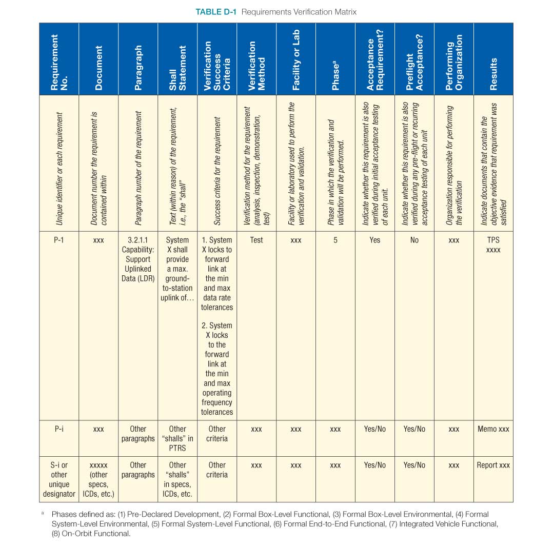
Appendix E: Creating the Validation Plan with a Validation Requirements Matrix
Note: See Appendix I for an outline of the Verification and Validation Plan. The matrix shown here (Table E-1) is Appendix D in that outline.
When developing requirements, it is important to identify a validation approach for how additional validation evaluation, testing, analysis, or other demonstrations will be performed to ensure customer/sponsor satisfaction.
There are a number of sources to draw from for creating the validation plan:
- ConOps
- Stakeholder/customer needs, goals, and objectives documentation
- Rationale statements for requirements and in verification requirements
- Lessons learned database
- System architecture modeling
- Test-as-you-fly design goals and constraints
- SEMP, HSIP, V&V plans
Validation products can take the form of a wide range of deliverables, including:
- Stakeholder evaluation and feedback
- Peer reviews
- Physical models of all fidelities
- Simulations
- Virtual modeling
- Tests
- Fit-checks
- Procedure dry-runs
- Integration activities (to inform on-orbit maintenance procedures)
- Phase-level review solicitation and feedback
Particular attention should be paid to the planning for life cycle phase since early validation can have a profound impact on the design and cost in the later life cycle phases.
Table E-1 shows an example validation matrix.
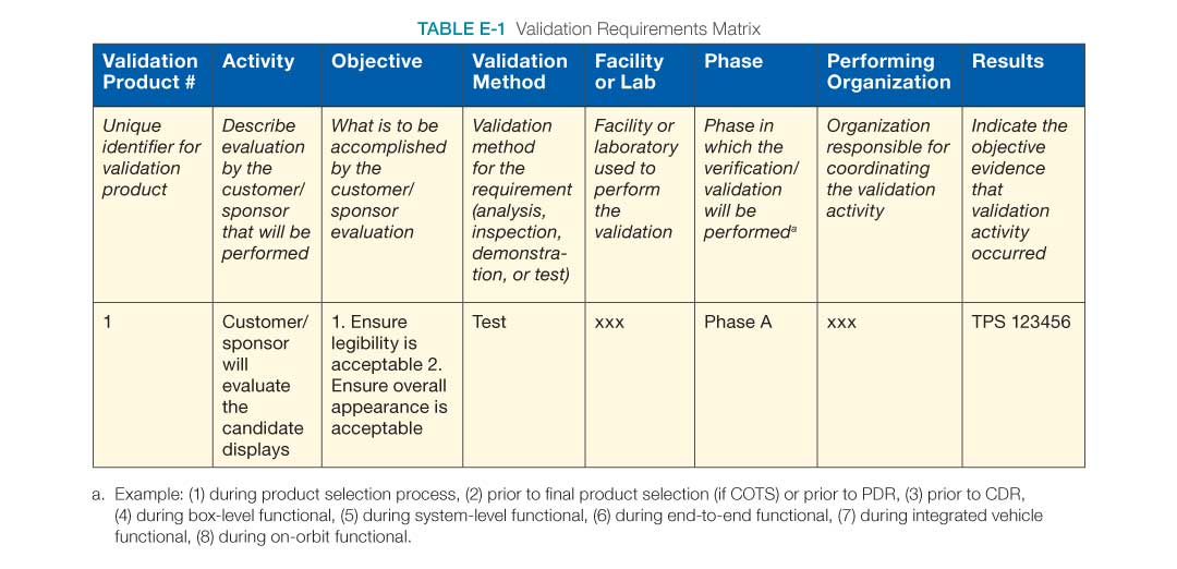
Appendix F: Functional, Timing, and State Analysis
This appendix was removed. For additional guidance on functional flow block diagrams, requirements allocation sheets/models, N-squared diagrams, timing analysis, and state analysis refer to Appendix F in the NASA Expanded Guidance for Systems Engineering at https://nen.nasa.gov/web/se/doc-repository.
Appendix G: Technology Assessment/Insertion
G.1 Introduction, Purpose, and Scope
In 2014, the Headquarters Office of Chief Engineer and Office of Chief Technologist conducted an Agency-wide study on Technical Readiness Level (TRL) usage and Technology Readiness Assessment (TRA) implementation. Numerous findings, observations, and recommendations were identified, as was a wealth of new guidance, best practices, and clarifications on how to interpret TRL and perform TRAs. These are presently being collected into a NASA TRA Handbook (in work), which will replace this appendix. In the interim, contact HQ/Steven Hirshorn on any specific questions on interpretation and application of TRL/TRA. Although the information contained in this appendix may change, it does provide some information until the TRA Handbook can be completed.
Agency programs and projects frequently require the development and infusion of new technological advances to meet mission goals, objectives, and resulting requirements. Sometimes the new technological advancement being infused is actually a heritage system that is being incorporated into a different architecture and operated in a different environment from that for which it was originally designed. It is important to recognize that the adaptation of heritage systems frequently requires technological advancement. Failure to account for this requirement can result in key steps of the development process being given short shrift—often to the detriment of the program/project. In both contexts of technological advancement (new and adapted heritage), infusion is a complex process that is often dealt with in an ad hoc manner differing greatly from project to project with varying degrees of success.
Technology infusion frequently results in schedule slips, cost overruns, and occasionally even in cancellations or failures. In post mortem, the root cause of such events is often attributed to “inadequate definition of requirements.” If such is indeed the root cause, then correcting the situation is simply a matter of defining better requirements, but this may not be the case—at least not totally.
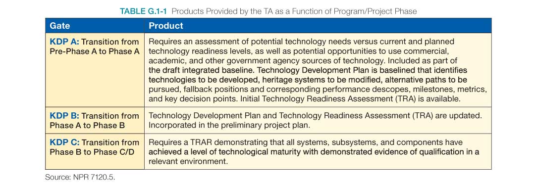
In fact, there are many contributors to schedule slip, cost overrun, and project cancellation and failure—among them lack of adequate requirements definition. The case can be made that most of these contributors are related to the degree of uncertainty at the outset of the project and that a dominant factor in the degree of uncertainty is the lack of understanding of the maturity of the technology required to bring the project to fruition and a concomitant lack of understanding of the cost and schedule reserves required to advance the technology from its present state to a point where it can be qualified and successfully infused with a high degree of confidence. Although this uncertainty cannot be eliminated, it can be substantially reduced through the early application of good systems engineering practices focused on understanding the technological requirements; the maturity of the required technology; and the technological advancement required to meet program/project goals, objectives, and requirements.
A number of processes can be used to develop the appropriate level of understanding required for successful technology insertion. The intent of this appendix is to describe a systematic process that can be used as an example of how to apply standard systems engineering practices to perform a comprehensive Technology Assessment (TA). The TA comprises two parts, a Technology Maturity Assessment (TMA) and an Advancement Degree of Difficulty Assessment (AD2). The process begins with the TMA which is used to determine technological maturity via NASA’s Technology Readiness Level (TRL) scale. It then proceeds to develop an understanding of what is required to advance the level of maturity through the AD2. It is necessary to conduct TAs at various stages throughout a program/project to provide the Key Decision Point (KDP) products required for transition between phases. (See Table G.1-1)
The initial TMA provides the baseline maturity of the system’s required technologies at program/project outset and allows monitoring progress throughout development. The final TMA is performed just prior to the Preliminary Design Review (PDR). It forms the basis for the Technology Readiness Assessment Report (TRAR), which documents the maturity of the technological advancement required by the systems, subsystems, and components demonstrated through test and analysis. The initial AD2 provides the material necessary to develop preliminary cost and to schedule plans and preliminary risk assessments. In subsequent assessments, the information is used to build the Technology Development Plan and in the process, identify alternative paths, fallback positions, and performance descope options. The information is also vital to preparing milestones and metrics for subsequent Earned Value Management (EVM).
The TMA is performed against the hierarchical breakdown of the hardware and software products of the program/project PBS to achieve a systematic, overall understanding at the system, subsystem, and component levels. (See Figure G.1-1.)
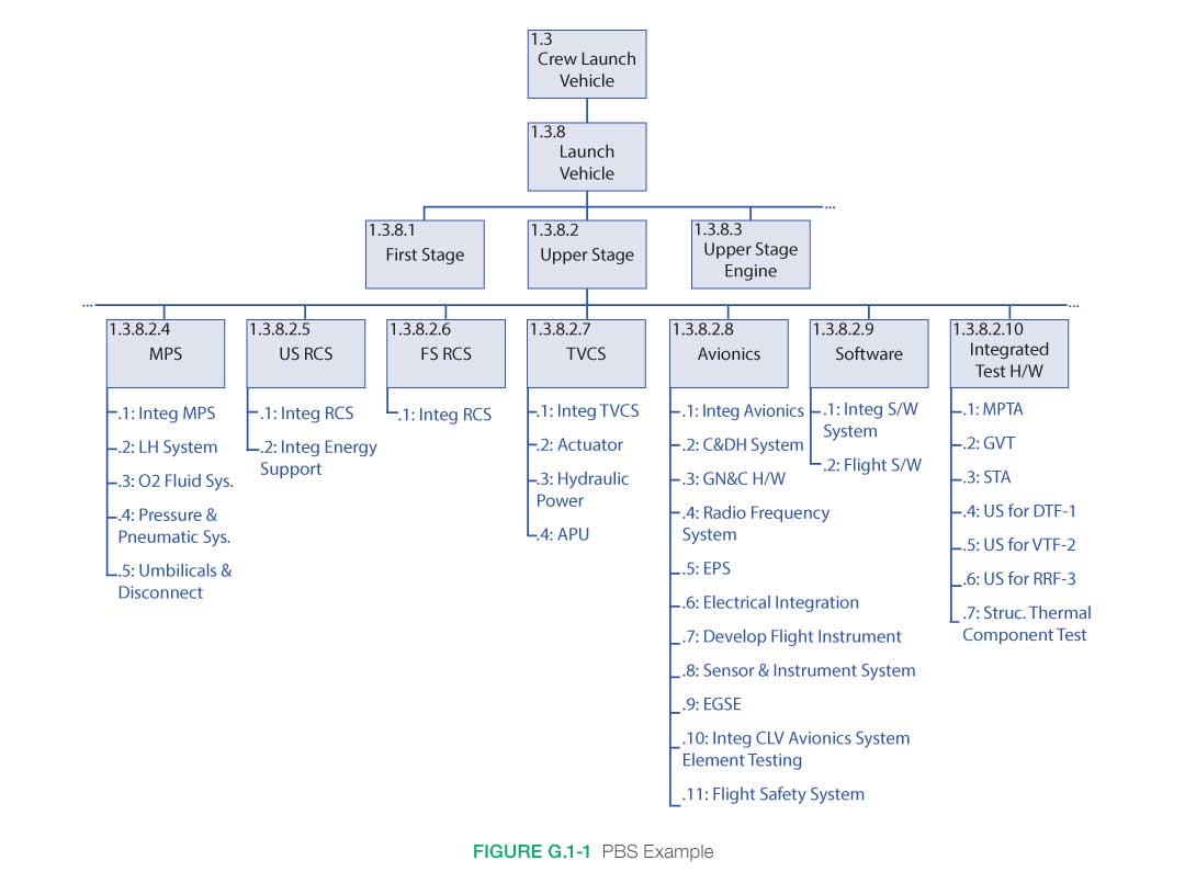
G.2 Inputs/Entry Criteria
It is extremely important that a TA process be defined at the beginning of the program/project and that it be performed at the earliest possible stage (concept development) and throughout the program/project through PDR. Inputs to the process will vary in level of detail according to the phase of the program/project, and even though there is a lack of detail in Pre-Phase A, the TA will drive out the major critical technological advancements required. Therefore, at the beginning of Pre-Phase A, the following should be provided:
- Refinement of TRL definitions.
- Definition of AD2.
- Definition of terms to be used in the assessment process.
- Establishment of meaningful evaluation criteria and metrics that will allow for clear identification of gaps and shortfalls in performance.
- Establishment of the TA team.
- Establishment of an independent TA review team.
G.3 How to Do Technology Assessment
The technology assessment process makes use of basic systems engineering principles and processes. As mentioned previously, it is structured to occur within the framework of the Product Breakdown Structure (PBS) to facilitate incorporation of the results. Using the PBS as a framework has a twofold benefit—it breaks the “problem” down into systems, subsystems, and components that can be more accurately assessed; and it provides the results of the assessment in a format that can be readily used in the generation of program costs and schedules. It can also be highly beneficial in providing milestones and metrics for progress tracking using EVM. As discussed above, it is a two-step process comprised of (1) the determination of the current technological maturity in terms of TRLs and (2) the determination of the difficulty associated with moving a technology from one TRL to the next through the use of the AD2.
Conceptual Level Activities
The overall process is iterative, starting at the conceptual level during program Formulation, establishing the initial identification of critical technologies, and establishing the preliminary cost, schedule, and risk mitigation plans. Continuing on into Phase A, the process is used to establish the baseline maturity, the Technology Development Plan, and the associated costs and schedule. The final TA consists only of the TMA and is used to develop the TRAR, which validates that all elements are at the requisite maturity level. (See Figure G.3-1.)
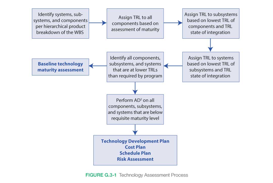
Even at the conceptual level, it is important to use the formalism of a PBS to avoid allowing important technologies to slip through the cracks. Because of the preliminary nature of the concept, the systems, subsystems, and components will be defined at a level that will not permit detailed assessments to be made. The process of performing the assessment, however, is the same as that used for subsequent, more detailed steps that occur later in the program/project where systems are defined in greater detail.
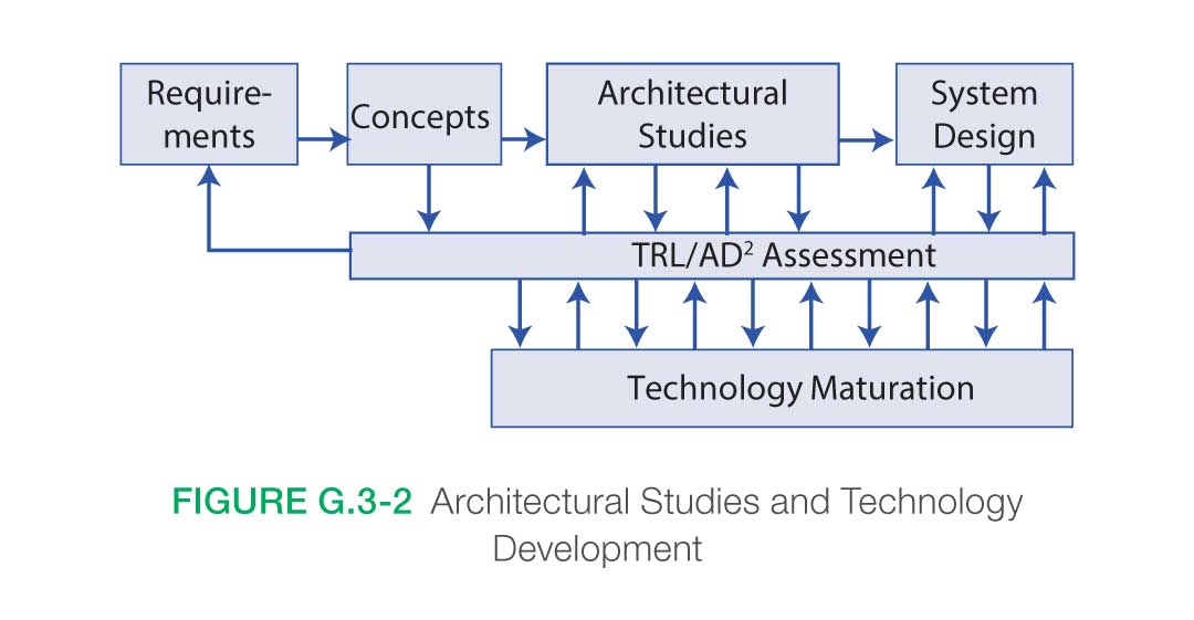
Architectural Studies
Once the concept has been formulated and the initial identification of critical technologies made, it is necessary to perform detailed architecture studies with the Technology Assessment Process intimately interwoven. (See Figure G.3-2.)
The purpose of the architecture studies is to refine end-item system design to meet the overall scientific requirements of the mission. It is imperative that there be a continuous relationship between architectural studies and maturing technology advances. The architectural studies should incorporate the results of the technology maturation, planning for alternative paths and identifying new areas required for development as the architecture is refined. Similarly, it is incumbent upon the technology maturation process to identify requirements that are not feasible and development routes that are not fruitful and to transmit that information to the architecture studies in a timely manner. It is also incumbent upon the architecture studies to provide feedback to the technology development process relative to changes in requirements. Particular attention should be given to “heritage” systems in that they are often used in architectures and environments different from those in which they were designed to operate.
G.4 Establishing TRLs
A Technology Readiness Level (TRL) is, at its most basic, a description of the performance history of a given system, subsystem, or component relative to a set of levels first described at NASA HQ in the 1980s. The TRL essentially describes the state of a given technology and provides a baseline from which maturity is gauged and advancement defined. (See Figure G.4-1.)
Programs are often undertaken without fully understanding either the maturity of key technologies or what is needed to develop them to the required level. It is impossible to understand the magnitude and scope of a development program without having a clear understanding of the baseline technological maturity of all elements of the system. Establishing the TRL is a vital first step on the way to a successful program. A frequent misconception is that in practice, it is too difficult to determine TRLs and that when you do, it is not meaningful. On the contrary, identifying TRLs can be a straightforward systems engineering process of determining what was demonstrated and under what conditions it was demonstrated.
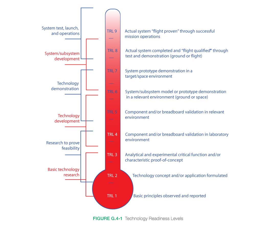
Terminology
At first glance, the TRL descriptions in Figure G.4-1 appear to be straightforward. It is in the process of trying to assign levels that problems arise. A primary cause of difficulty is in terminology; e.g., everyone knows what a breadboard is, but not everyone has the same definition. Also, what is a “relevant environment?” What is relevant to one application may or may not be relevant to another. Many of these terms originated in various branches of engineering and had, at the time, very specific meanings to that particular field. They have since become commonly used throughout the engineering field and often acquire differences in meaning from discipline to discipline, some differences subtle, some not so subtle. “Breadboard,” for example, comes from electrical engineering where the original use referred to checking out the functional design of an electrical circuit by populating a “breadboard” with components to verify that the design operated as anticipated. Other terms come from mechanical engineering, referring primarily to units that are subjected to different levels of stress under testing, e.g., qualification, protoflight, and flight units. The first step in developing a uniform TRL assessment (see Figure G.4-2) is to define the terms used. It is extremely important to develop and use a consistent set of definitions over the course of the program/project.
Judgment Calls
Having established a common set of terminology, it is necessary to proceed to the next step: quantifying “judgment calls” on the basis of past experience. Even with clear definitions, judgment calls will be required when it comes time to assess just how similar a given element is relative to what is needed (i.e., is it close enough to a prototype to be considered a prototype, or is it more like an engineering breadboard?). Describing what has been done in terms of form, fit, and function provides a means of quantifying an element based on its design intent and subsequent performance. The current definitions for software TRLs are contained in NPR 7123.1, NASA Systems Engineering Processes and Requirements.
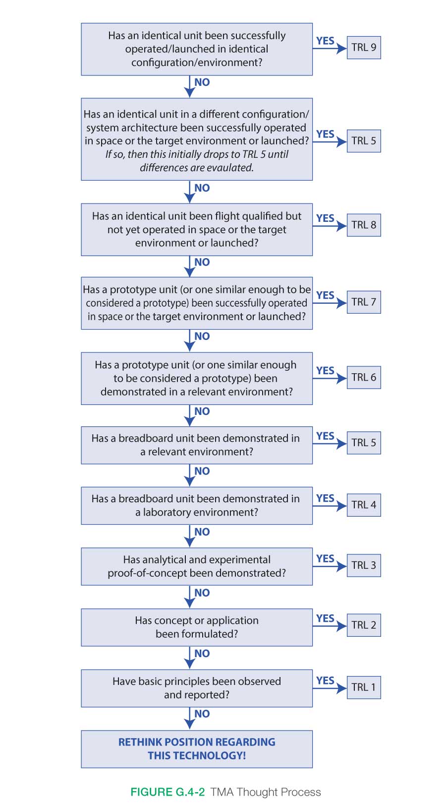
Assessment Team
A third critical element of any assessment relates to the question of who is in the best position to make judgment calls relative to the status of the technology in question. For this step, it is extremely important to have a well-balanced, experienced assessment team. Team members do not necessarily have to be discipline experts. The primary expertise required for a TRL assessment is that the systems engineer/user understands the current state of the art in applications. User considerations are evaluated by HFE personnel who understand the challenges of technology insertions at various stages of the product life cycle. Having established a set of definitions, defined a process for quantifying judgment calls, and assembled an expert assessment team, the process primarily consists of asking the right questions. The flowchart depicted in Figure G.4-2 demonstrates the questions to ask to determine TRL at any level in the assessment.
Heritage Systems
Note the second box particularly refers to heritage systems. If the architecture and the environment have changed, then the TRL drops to TRL 5—at least initially. Additional testing may need to be done for heritage systems for the new use or new environment. If in subsequent analysis the new environment is sufficiently close to the old environment or the new architecture sufficiently close to the old architecture, then the resulting evaluation could be TRL 6 or 7, but the most important thing to realize is that it is no longer at TRL 9. Applying this process at the system level and then proceeding to lower levels of subsystem and component identifies those elements that require development and sets the stage for the subsequent phase, determining the AD2.
Formal Process for Determining TRLs
A method for formalizing this process is shown in Figure G.4-3. Here, the process has been set up as a table: the rows identify the systems, subsystems, and components that are under assessment. The columns identify the categories that will be used to determine the TRL; i.e., what units have been built, to what scale, and in what environment have they been tested. Answers to these questions determine the TRL of an item under consideration. The TRL of the system is determined by the lowest TRL present in the system; i.e., a system is at TRL 2 if any single element in the system is at TRL 2. The problem of multiple elements being at low TRLs is dealt with in the AD2 process. Note that the issue of integration affects the TRL of every system, subsystem, and component. All of the elements can be at a higher TRL, but if they have never been integrated as a unit, the TRL will be lower for the unit. How much lower depends on the complexity of the integration. The assessed complexity depends upon the combined judgment of the engineers. It is important to have a good cross-section of senior people sitting in judgment.
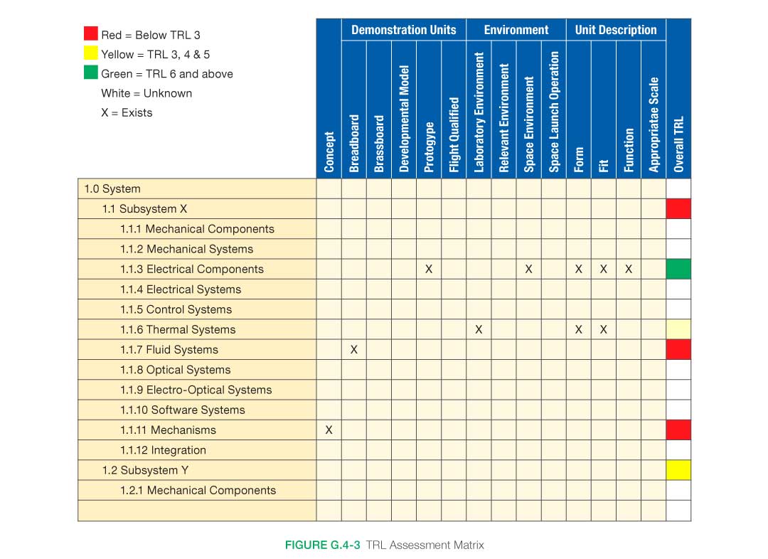
Appendix H: Integration Plan Outline
H.1 Purpose
The integration plan defines the integration and verification strategies for a project interface with the system design and decomposition into the lower-level elements. The integration plan is structured to bring the elements together to assemble each subsystem and to bring all of the subsystems together to assemble the system/product. The primary purposes of the integration plan are: (1) to describe this coordinated integration effort that supports the implementation strategy, (2) to describe for the participants what needs to be done in each integration step, and (3) to identify the required resources and when and where they will be needed.
H.2 Questions/Checklist
- Does the integration plan include and cover integration of all of the components and subsystems of the project, either developed or purchased?
- Does the integration plan account for all external systems to be integrated with the system (for example, communications networks, field equipment, other complete systems owned by the government or owned by other government agencies)?
- Does the integration plan fully support the implementation strategy, for example, when and where the subsystems and system are to be used?
- Does the integration plan mesh with the verification plan?
- For each integration step, does the integration plan define what components and subsystems are to be integrated?
- For each integration step, does the integration plan identify all the needed participants and define what their roles and responsibilities are?
- Does the integration plan establish the sequence and schedule for every integration step?
- Does the integration plan spell out how integration problems are to be documented and resolved?
H.3 Integration Plan Contents
Title Page
The title page should follow the NASA procedures or style guide. At a minimum, it should contain the following information:
- INTEGRATION PLAN FOR THE [insert name of project] AND [insert name of organization]
- Contract number
- Date that the document was formally approved
- The organization responsible for preparing the document
- Internal document control number, if available
- Revision version and date issued
1.0 Purpose of Document
This section gives a brief statement of the purpose of this document. It is the plan for integrating the components and subsystems of the project prior to verification.
2.0 Scope of Project
This section gives a brief description of the planned project and the purpose of the system to be built. Special emphasis is placed on the project’s deployment complexities and challenges.
3.0 Integration Strategy
This section tells the reader what the high-level plan for integration is and, most importantly, why the integration plan is structured the way it is. The integration plan is subject to several, sometimes conflicting, constraints. Also, it is one part of the larger process of build, integrate, verify, and deploy, all of which should be synchronized to support the same project strategy. So, for even a moderately complex project, the integration strategy, which is based on a clear and concise statement of the project’s goals and objectives, is described here at a high but all-inclusive level. It may also be necessary to describe the analysis of alternative strategies to make it clear why this particular strategy was selected.
The same strategy is the basis for the build plan, the verification plan, and the deployment plan. This section covers and describes each step in the integration process. It describes what components are integrated at each step and gives a general idea of what threads of the operational capabilities (requirements) are covered. It ties the plan to the previously identified goals and objectives so the stakeholders can understand the rationale for each integration step. This summary-level description also defines the schedule for all the integration efforts.
4.0 Phase 1 Integration
This and the following sections define and explain each step in the integration process. The intent here is to identify all the needed participants and to describe to them what they have to do. In general, the description of each integration step should identify the following:
- The location of the activities.
- The project-developed equipment and software products to be integrated. Initially this is just a high-level list, but eventually the list should be exact and complete, showing part numbers and quantity.
- Any support equipment (special software, test hardware, software stubs, and drivers to simulate yet-to-be-integrated software components, external systems) needed for this integration step. The same support equipment is most likely needed for the subsequent verification step.
- All integration activities that need to be performed after installation, including integration with onsite systems and external systems at other sites.
- A description of the verification activities, as defined in the applicable verification plan, that occur after this integration step.
- The responsible parties for each activity in the integration step.
- The schedule for each activity.
5.0 Multiple Phase Integration Steps (1 or N steps)
This and any needed additional sections follow the format for Section 3.0. Each covers each step in a multiple-step integration effort.
Appendix I: Integration Plan Outline
Sample Outline
The Verification and Validation (V&V) Plan needs to be baselined after the comments from PDR are incorporated. In this annotated outline, the use of the term “system” is indicative of the entire scope for which this plan is developed. This may be an entire spacecraft, just the avionics system, or a card within the avionics system. Likewise, the terms “end item,” “subsystem,” or “element” are meant to imply the lower-level products that, when integrated together, will produce the “system.” The general term “end item” is used to encompass activities regardless of whether the end item is a hardware or software element.
The various sections are intended to move from the high-level generic descriptions to the more detailed. The sections also flow from the lower-level items in the product layer to larger and larger assemblies and to the completely integrated system. The sections also describe how that system may be integrated and further verified/validated with its externally interfacing elements. This progression will help build a complete understanding of the overall plans for verification and validation.
1.0 Introduction
1.1 Purpose and Scope
This section states the purpose of this Verification and Validation Plan and the scope (i.e., systems) to which it applies. The purpose of the V&V Plan is to identify the activities that will establish compliance with the requirements (verification) and to establish that the system will meet the customers’ expectations (validation).
1.2 Responsibility and Change Authority
This section will identify who has responsibility for the maintenance of this plan and who or what board has the authority to approve any changes to it.
1.3 Definitions
This section will define any key terms used in the plan. The section may include the definitions of verification, validation, analysis, test, demonstration, and test. See appendix B of this handbook for definitions of these and other terms that might be used.
2.0 Applicable and Reference Documents
2.1 Applicable Documents
These are the documents that may impose additional requirements or from which some of the requirements have been taken.
2.2 Reference Documents
These are the documents that are referred to within the V&V Plan that do not impose requirements, but which may have additional useful information.
2.3 Order of Precedence
This section identifies which documents take precedence whenever there are conflicting requirements.
3.0 System Description
3.1 System Requirements Flowdown
This section describes where the requirements for this system come from and how they are flowed down to subsystems and lower-level elements. It should also indicate what method will be used to perform the flowdown and bidirectional traceability of the requirements: spreadsheet, model, or other means. It can point to the file, document, or spreadsheet that captures the actual requirements flowdown.
3.2 System Architecture
This section describes the system that is within the scope of this V&V Plan. The description should be enough so that the V&V activities will have the proper context and be understandable.
3.3 End Item Architectures
This section describes each of the major end items (subsystems, elements, units, modules, etc.) that when integrated together, will form the overall system that is the scope of this V&V Plan.
3.3.1 System End Item A
This section describes the first major end item/subsystem in more detail so that the V&V activities have context and are understandable.
3.3.n System End Item n
Each end item/subsystem is separately described in a similar manner as above.
3.4 Ground Support Equipment
This section describes any major ground-support equipment that will be used during the V&V activities. This may include carts for supplying power or fuel, special test fixtures, lifting aids, simulators, or other type of support.
3.5 Other Architecture Descriptions
This section describes any other items that are important for the V&V activities but which are not included in the sections above. This may be an existing control center, training facility, or other support.
4.0 Verification and Validation Process
This section describes the process that will be used to perform verification and validation.
4.1 Verification and Validation Management Responsibilities
This section describes the responsibilities of key players in the V&V activities. It may include identification and duty description for test directors/conductors, managers, facility owners, boards, and other key stakeholders.
4.2 Verification Methods
This section defines and describes the methods that will be used during the verification activities.
4.2.1 Analysis
Defines what this verification method means (See Appendix B of this handbook) and how it will be applied to this system.
4.2.2 Inspection
Defines what this verification method means (See Appendix B of this handbook) and how it will be applied to this system.
4.2.3 Demonstration
Defines what this verification method means (See Appendix B of this handbook) and how it will be applied to this system.
4.2.4 Test
Defines what this verification method means (See Appendix B of this handbook) and how it will be applied to this system. This category may need to be broken down into further categories.
4.2.4.1 Qualification Testing
This section describes the test philosophy for the environmental and other testing that is performed at higher than normal levels to ascertain margins and performance in worst-case scenarios. Includes descriptions of how the minimum and maximum extremes will be determined for various types of tests (thermal, vibration, etc.), whether it will be performed at a component, subsystem, or system level, and the pedigree (flight unit, qualification unit, engineering unit, etc.) of the units these tests will be performed on.
4.2.4.2 Other Testing
This section describes any other testing that will be used as part of the verification activities that are not part of the qualification testing. It includes any testing of requirements within the normal operating range of the end item. It may include some engineering tests that will form the foundation or provide dry runs for the official verification testing.
4.3 Validation Methods
This section defines and describes the methods to be used during the validation activities.
4.3.1 Analysis
Defines what this validation method means (See Appendix B of this handbook) and how it will be applied to this system.
4.3.2 Inspection
Defines what this validation method means (See Appendix B of this handbook) and how it will be applied to this system.
4.3.3 Demonstration
Defines what this validation method means (See Appendix B of this handbook) and how it will be applied to this system.
4.3.4 Test
Defines what this validation method means (See Appendix B of this handbook) and how it will be applied to this system. This category may need to be broken down into further categories such as end-to-end testing, testing with humans, etc.)
4.4 Certification Process
Describes the overall process by which the results of these verification and validation activities will be used to certify that the system meets its requirements and expectations and is ready to be put into the field or fly. In addition to the verification and validation results, the certification package may also include special forms, reports, safety documentation, drawings, waivers, or other supporting documentation.
4.5 Acceptance Testing
Describes the philosophy of how/which of the verification/validation activities will be performed on each of the operational units as they are manufactured/coded and are readied for flight/use. Includes how/if data packages will be developed and provided as part of the delivery.
5.0 Verification and Validation Implementation
5.1 System Design and Verification and Validation Flow
This section describes how the system units/modules will flow from manufacturing/coding through verification and validation. Includes whether each unit will be verified/validated separately, or assembled to some level and then evaluated or other statement of flow.
5.2 Test Articles
This section describes the pedigree of test articles that will be involved in the verification/validation activities. This may include descriptions of breadboards, prototypes, engineering units, qualification units, protoflight units, flight units, or other specially named units. A definition of what is meant by these terms needs to be included to ensure clear understanding of the expected pedigree of each type of test article. Descriptions of what kind of test/analysis activities will be performed on each type of test article is included.
5.3 Support Equipment
This section describes any special support equipment that will be needed to perform the verification/validation activities. This will be a more detailed description than is stated in Section 3.4 of this outline.
5.4 Facilities
This section identifies and describes major facilities that will be needed in order to accomplish the verification and validation activities. These may include environmental test facilities, computational facilities, simulation facilities, training facilities, test stands, and other facilities as needed.
6.0 End Item Verification and Validation
This section describes in detail the V&V activities that will be applied to the lower-level subsystems/elements/end items. It can point to other stand-alone descriptions of these tests if they will be generated as part of organizational responsibilities for the products at each product layer.
6.1 End Item A
This section focuses in on one of the lower-level end items and describes in detail what type of verification activities it will undergo.
6.1.1 Developmental/Engineering Unit Evaluations
This section describes what kind of testing, analysis, demonstrations, or inspections the prototype/engineering or other types of units/modules will undergo prior to performing official verification and validation.
6.1.2 Verification Activities
This section describes in detail the verification activities that will be performed on this end item.
6.1.2.1 Verification by Testing
This section describes all verification testing that will be performed on this end item.
6.1.2.1.1 Qualification Testing
This section describes the test environmental and other testing that is performed at higher than normal levels to ascertain margins and performance in worst-case scenarios. It includes what minimum and maximum extremes will be used on qualification tests (thermal, vibration, etc.) of this unit, whether it will be performed at a component, subsystem, or system level, and the pedigree (flight unit, qualification unit, engineering unit, etc.) of the units these tests will be performed on.
6.1.2.1.2 Other Testing
This section describes all other verification tests that are not performed as part of the qualification testing. These will include verification of requirements in the normal operating ranges.
6.1.2.2 Verification by Analysis
This section describes the verifications that will be performed by analysis (including verification by similarity). This may include thermal analysis, stress analysis, analysis of fracture control, materials analysis, Electrical, Electronic, and Electromechnical (EEE) parts analysis, and other analyses as needed for the verification of this end item.
6.1.2.3 Verification by Inspection
This section describes the verifications that will be performed for this end item by inspection.
6.1.2.4 Verification Demonstration
This section describes the verifications that will be performed for this end item by demonstration.
6.1.3 Validation Activities
6.1.3.1 Validation by Testing
This section describes what validation tests will be performed on this end item.
6.1.3.2 Validation by Analysis
This section describes the validation that will be performed for this end item through analysis.
6.1.3.3 Validation by Inspection
This section describes the validation that will be performed for this end item through inspection.
6.1.3.4 Validation by Demonstration
This section describes the validations that will be performed for this end item by demonstration.
6.1.4 Acceptance Testing
This section describes the set of tests, analysis, demonstrations, or inspections that will be performed on the flight/final version of the end item to show it has the same design as the one that is being verified, that the workmanship on this end item is good, and that it performs the identified functions properly.
6.n End Item n
In a similar manner as above, a description of how each end item that makes up the system will be verified and validated is made.
7.0 System Verification and Validation
7.1 End-Item Integration
This section describes how the various end items will be assembled/integrated together, verified and validated. For example, the avionics and power systems may be integrated and tested together to ensure their interfaces and performance is as required and expected prior to integration with a larger element. This section describes the verification and validation that will be performed on these major assemblies. Complete system integration will be described in later sections.
7.1.1 Developmental/Engineering Unit Evaluations
This section describes the unofficial (not the formal verification/validation) testing/analysis that will be performed on the various assemblies that will be tested together and the pedigree of the units that will be used. This may include system-level testing of configurations using engineering units, breadboard, simulators, or other forms or combination of forms.
7.1.2 Verification Activities
This section describes the verification activities that will be performed on the various assemblies.
7.1.2.1 Verification by Testing
This section describes all verification testing that will be performed on the various assemblies. The section may be broken up to describe qualification testing performed on the various assemblies and other types of testing.
7.1.2.2 Verification by Analysis
This section describes all verification analysis that will be performed on the various assemblies.
7.1.2.3 Verification by Inspection
This section describes all verification inspections that will be performed on the various assemblies.
7.1.2.4 Verification by Demonstration
This section describes all verification demonstrations that will be performed on the various assemblies.
7.1.3 Validation Activities
7.1.3.1 Validation by Testing
This section describes all validation testing that will be performed on the various assemblies.
7.1.3.2 Validation by Analysis
This section describes all validation analysis that will be performed on the various assemblies.
7.1.3.3 Validation by Inspection
This section describes all validation inspections that will be performed on the various assemblies.
7.1.3.4 Validation by Demonstration
This section describes all validation demonstrations that will be performed on the various assemblies.
7.2 Complete System Integration
This section describes the verification and validation activities that will be performed on the systems after all its assemblies are integrated together to form the complete integrated system. In some cases this will not be practical. Rationale for what cannot be done should be captured.
7.2.1 Developmental/Engineering Unit Evaluations
This section describes the unofficial (not the formal verification/validation) testing/analysis that will be performed on the complete integrated system and the pedigree of the units that will be used. This may include system-level testing of configurations using engineering units, breadboard, simulators, or other forms or combination of forms.
7.2.2 Verification Activities
This section describes the verification activities that will be performed on the completely integrated system
7.2.2.1 Verification Testing
This section describes all verification testing that will be performed on the integrated system. The section may be broken up to describe qualification testing performed at the integrated system level and other types of testing.
7.2.2.2 Verification Analysis
This section describes all verification analysis that will be performed on the integrated system.
7.2.2.3 Verification Inspection
This section describes all verification inspections that will be performed on the integrated system.
7.2.2.4 Verification Demonstration
This section describes all verification demonstrations that will be performed on the integrated system.
7.2.3 Validation Activities
This section describes the validation activities that will be performed on the completely integrated system.
7.2.3.1 Validation by Testing
This section describes all validation testing that will be performed on the integrated system.
7.2.3.2 Validation by Analysis
This section describes all validation analysis that will be performed on the integrated system.
7.2.3.3 Validation by Inspection
This section describes the validation inspections that will be performed on the integrated system.
7.2.3.4 Validation by Demonstration
This section describes the validation demonstrations that will be performed on the integrated system.
8.0 Program Verification and Validation
This section describes any further testing that the system will be subjected to. For example, if the system is an instrument, the section may include any verification/validation that the system will undergo when integrated into its spacecraft/platform. If the system is a spacecraft, the section may include any verification/validation the system will undergo when integrated with its launch vehicle.
8.1 Vehicle Integration
This section describes any further verification or validation activities that will occur when the system is integrated with its external interfaces.
8.2 End-to-End Integration
This section describes any end-to-end testing that the system may undergo. For example, this configuration would include data being sent from a ground control center through one or more relay satellites to the system and back.
8.3 On-Orbit V&V Activities
This section describes any remaining verification/validation activities that will be performed on a system after it reaches orbit or is placed in the field.
9.0 System Certification Products
This section describes the type of products that will be generated and provided as part of the certification process. This package may include the verification and validation matrix and results, pressure vessel certifications, special forms, materials certifications, test reports or other products as is appropriate for the system being verified and validated.
Appendix A: Acronyms and Abbreviations
This is a list of all the acronyms and abbreviations used in the V&V Plan and their spelled-out meaning.
Appendix B: Definition of Terms
This section is a definition of the key terms that are used in the V&V Plan.
Appendix C: Requirement Verification Matrix
The V&V Plan needs to be baselined after the comments from PDR are incorporated. The information in this section may take various forms. It could be a pointer to another document or model where the matrix and its results may be found. This works well for large projects using a requirements-tracking application. The information in this section could also be the requirements matrix filled out with all but the results information and a pointer to where the results can be found. This allows the key information to be available at the time of baselining. For a smaller project, this may be the completed verification matrix. In this case, the V&V Plan would be filled out as much as possible before. See Appendix D for an example of a verification matrix.
Appendix D: Validation Matrix
As with the verification matrix, this product may take various forms from a completed matrix to just a pointer for where the information can be found. Appendix E provides an example of a validation matrix.
Appendix J: SEMP Content Outline
J.1 SEMP Content
The Systems Engineering Management Plan (SEMP) is the foundation document for the technical and engineering activities conducted during the project. The SEMP conveys information to all of the personnel on the technical integration methodologies and activities for the project within the scope of the project plan. SEMP content can exist as a stand-alone document or, for smaller projects, in higher-level project documentation.
The SEMP provides the specifics of the technical effort and describes what technical processes will be used, how the processes will be applied using appropriate activities, how the project will be organized to accomplish the activities, and the resources required for accomplishing the activities. The SEMP provides the framework for realizing the appropriate work products that meet the entry and success criteria of the applicable project life cycle phases to provide management with necessary information for assessing technical progress.
Because the SEMP provides the specific technical and management information to understand the technical integration and interfaces, its documentation and approval serve as an agreement within the project of how the technical work will be conducted. The SEMP communicates to the team itself, managers, customers, and other stakeholders the technical effort that will be performed by the assigned technical team.
The technical team, working under the overall program/project plan, develops and updates the SEMP as necessary. The technical team works with the project manager to review the content and obtain concurrence. The SEMP includes the following three general sections:
- Technical program planning and control, which describe the processes for planning and control of the engineering efforts for the design, development, test, and evaluation of the system.
- Systems engineering processes, which include specific tailoring of the systems engineering process as described in the NPR, implementation procedures, trade study methodologies, tools, and models to be used.
- Engineering specialty integration describes the integration of the technical disciplines’ efforts into the systems engineering process and summarizes each technical discipline effort and cross references each of the specific and relevant plans.
The SEMP outline in this appendix is guidance to be used in preparing a stand-alone project SEMP. The level of detail in the project SEMP should be adapted based on the size of the project. For a small project, the material in the SEMP can be placed in the project plan’s technical summary, and this annotated outline should be used as a topic guide.
Some additional important points on the SEMP:
- The SEMP is a living document. The initial SEMP is used to establish the technical content of the engineering work early in the Formulation Phase for each project and updated as needed throughout the project life cycle. Table J-1 provides some high level guidance on the scope of SEMP content based on the life cycle phase.
- Project requirements that have been tailored or significant customization of SE processes should be described in the SEMP.
- For multi-level projects, the SEMP should be consistent with higher-level SEMPs and the project plan.
- For a technical effort that is contracted, the SEMP should include details on developing requirements for source selection, monitoring performance, and transferring and integrating externally produced products to NASA.
J.2 Terms Used
Terms used in the SEMP should have the same meaning as the terms used in the NPR 7123.1, Systems Engineering Processes and Requirements.
J.3 Annotated Outline
Title Page
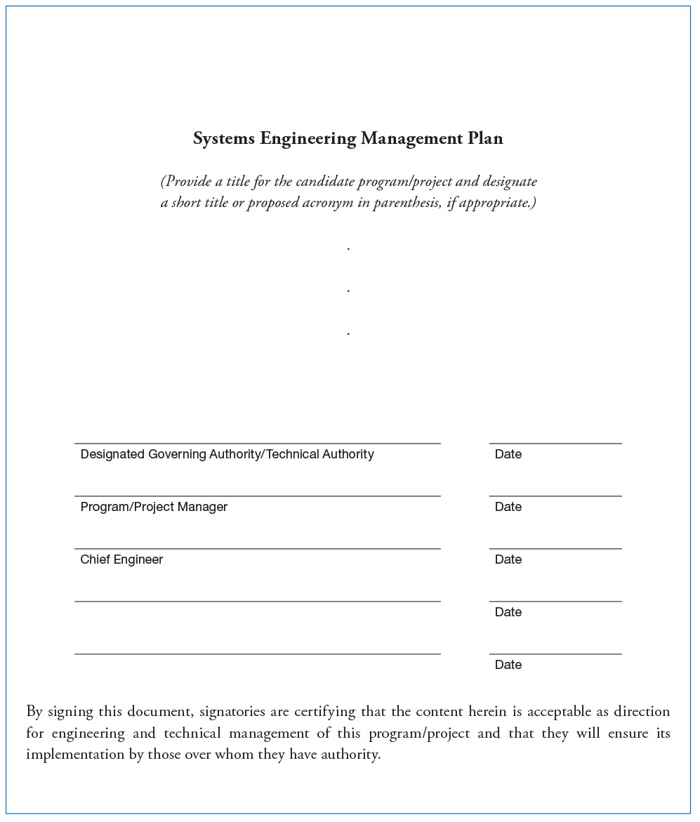
1.0 Purpose and Scope
This section provides a brief description of the purpose, scope, and content of the SEMP.
- Purpose: This section should highlight the intent of the SEMP to provide the basis for implementing and communicating the technical effort.
- Scope: The scope describes the work that encompasses the SE technical effort required to generate the work products. The plan is used by the technical team to provide personnel the information necessary to successfully accomplish the required task.
- Content: This section should briefly describe the organization of the document.
2.0 Applicable Documents
This section of the SEMP lists the documents applicable to this specific project and its SEMP implementation. This section should list major standards and procedures that this technical effort for this specific project needs to follow. Examples of specific procedures to list could include procedures for hazardous material handling, crew training plans for control room operations, special instrumentation techniques, special interface documentation for vehicles, and maintenance procedures specific to the project.
3.0 Technical Summary
This section contains an executive summary describing the problem to be solved by this technical effort and the purpose, context, and products to be developed and integrated with other interfacing systems identified.
Key Questions
- What is the problem we’re trying to solve?
- What are the influencing factors?
- What are the critical questions?
- What are the overall project constraints in terms of cost, schedule, and technical performance
- How will we know when we have adequately defined the problem?
- Who are the customers?
- Who are the users?
- What are the customer and user priorities?
- What is the relationship to other projects?
3.1 System Description
This section contains a definition of the purpose of the system being developed and a brief description of the purpose of the products of the product layer of the system structure to which this SEMP applies. Each product layer includes the system end products and their subsystems and the supporting or enabling products and any other work products (plans, baselines) required for the development of the system. The description should include any interfacing systems and system products, including humans with which the system products will interact physically, cognitively, functionally, or electronically.
3.2 System Structure
This section contains an explanation of how the technical portion of the product layer (including enabling products, technical cost, and technical schedule) will be developed, how the resulting product layers will be integrated into the project portion of the WBS, and how the overall system structure will be developed. This section contains a description of the relationship of the specification tree and the drawing tree with the products of the system structure and how the relationship and interfaces of the system end products and their life cycle-enabling products will be managed throughout the planned technical effort.
3.3 Product Integration
This section contains an explanation of how the products will be integrated and describes clear organizational responsibilities and interdependencies and whether the organizations are geographically dispersed or managed across Centers. This section should also address how products created under a diverse set of contracts are to be integrated, including roles and responsibilities. This includes identifying organizations—intra-and inter-NASA, other Government agencies, contractors, or other partners—and delineating their roles and responsibilities. Product integration includes the integration of analytical products.
When components or elements will be available for integration needs to be clearly understood and identified on the schedule to establish critical schedule issues.
3.4 Planning Context
This section contains the programmatic constraints (e.g., NPR 7120.5) that affect the planning and implementation of the common technical processes to be applied in performing the technical effort. The constraints provide a linkage of the technical effort with the applicable product life cycle phases covered by the SEMP including, as applicable, milestone decision gates, major technical reviews, key intermediate events leading to project completion, life cycle phase, event entry and success criteria, and major baseline and other work products to be delivered to the sponsor or customer of the technical effort.
3.5 Boundary of Technical Effort
This section contains a description of the boundary of the general problem to be solved by the technical effort, including technical and project constraints that affect the planning. Specifically, it identifies what can be controlled by the technical team (inside the boundary) and what influences the technical effort and is influenced by the technical effort but not controlled by the technical team (outside the boundary). Specific attention should be given to physical, cognitive, functional, and electronic interfaces across the boundary.
A description of the boundary of the system can include the following:
- Definition of internal and external elements/items involved in realizing the system purpose as well as the system boundaries in terms of space, time, physical, and operational.
- Identification of what initiates the transitions of the system to operational status and what initiates its disposal is important. General and functional descriptions of the subsystems inside the boundary.
- Current and established subsystem performance characteristics.
- Interfaces and interface characteristics.
- Functional interface descriptions and functional flow diagrams.
- Key performance interface characteristics.
- Current integration strategies and architecture.
- Documented Human System Integration Plan (HSIP)
3.6 Cross References
This section contains cross references to appropriate nontechnical plans and critical reference material that interface with the technical effort. It contains a summary description of how the technical activities covered in other plans are accomplished as fully integrated parts of the technical effort.
4.0 Technical Effort Integration
This section describes how the various inputs to the technical effort will be integrated into a coordinated effort that meets cost, schedule, and performance objectives.
The section should describe the integration and coordination of the specialty engineering disciplines into the systems engineering process during each iteration of the processes. Where there is potential for overlap of specialty efforts, the SEMP should define the relative responsibilities and authorities of each specialty. This section should contain, as needed, the project’s approach to the following:
- Concurrent engineering
- The activity phasing of specialty engineering
- The participation of specialty disciplines
- The involvement of specialty disciplines,
- The role and responsibility of specialty disciplines,
- The participation of specialty disciplines in system decomposition and definition
- The role of specialty disciplines in verification and validation
- Reliability
- Maintainability
- Quality assurance
- Integrated logistics
- Human engineering
- Safety
- Producibility
- Survivability/vulnerability
- National Environmental Policy Act (NEPA) compliance
- Launch approval/flight readiness
The approach for coordination of diverse technical disciplines and integration of the development tasks should be described. For example, this can include the use of multidiscipline integrated teaming approaches—e.g., an HSI team—or specialized control boards. The scope and timing of the specialty engineering tasks should be described along with how specialty engineering disciplines are represented on all technical teams and during all life cycle phases of the project.
4.1 Responsibility and Authority
This section describes the organizing structure for the technical teams assigned to this technical effort and includes how the teams will be staffed and managed.
Key Questions
- What organization/panel will serve as the designated governing authority for this project?
- How will multidisciplinary teamwork be achieved?
- What are the roles, responsibilities, and authorities required to perform the activities of each planned common technical process?
- What should be the planned technical staffing by discipline and expertise level?
- What is required for technical staff training?
- How will the assignment of roles, responsibilities, and authorities to appropriate project stakeholders or technical teams be accomplished?
- How are we going to structure the project to enable this problem to be solved on schedule and within cost?
- What does systems engineering management bring to the table?
The section should provide an organization chart and denote who on the team is responsible for each activity. It should indicate the lines of authority and responsibility. It should define the resolution authority to make decisions/decision process. It should show how the engineers/engineering disciplines relate.
The systems engineering roles and responsibilities need to be addressed for the following: project office, user, Contracting Officer’s Representative (COR), systems engineering, design engineering, specialty engineering, and contractor.
4.2 Contractor Integration
This section describes how the technical effort of in-house and external contractors is to be integrated with the NASA technical team efforts. The established technical agreements should be described along with how contractor progress will be monitored against the agreement, how technical work or product requirement change requests will be handled, and how deliverables will be accepted. The section specifically addresses how interfaces between the NASA technical team and the contractor will be implemented for each of the 17 common technical processes. For example, it addresses how the NASA technical team will be involved with reviewing or controlling contractor-generated design solution definition documentation or how the technical team will be involved with product verification and product validation activities.
Key deliverables for the contractor to complete their systems and those required of the contractor for other project participants need to be identified and established on the schedule.
4.3 Analytical Tools that Support Integration
This section describes the methods (such as integrated computer-aided tool sets, integrated work product databases, and technical management information systems) that will be used to support technical effort integration.
5.0 Common Technical Processes Implementation
Each of the 17 common technical processes will have a separate subsection that contains a plan for performing the required process activities as appropriately tailored. (See NPR 7123.1 for the process activities required and tailoring.) Implementation of the 17 common technical processes includes (1) the generation of the outcomes needed to satisfy the entry and success criteria of the applicable product life cycle phase or phases identified in D.4.4.4, and (2) the necessary inputs for other technical processes. These sections contain a description of the approach, methods, and tools for:
- Identifying and obtaining adequate human and nonhuman resources for performing the planned process, developing the work products, and providing the services of the process.
- Assigning responsibility and authority for performing the planned process (e.g., RACI matrix, [http://en.wikipedia.org/wiki/Responsibility_assignment_matrix]), developing the work products, and providing the services of the process.
- Training the technical staff performing or supporting the process, where training is identified as needed.
- Designating and placing designated work products of the process under appropriate levels of configuration management.
- Identifying and involving stakeholders of the process.
- Monitoring and controlling the systems engineering processes.
- Identifying, defining, and tracking metrics and success.
- Objectively evaluating adherence of the process and the work products and services of the process to the applicable requirements, objectives, and standards and addressing noncompliance.
- Reviewing activities, status, and results of the process with appropriate levels of management and resolving issues.
This section should also include the project-specific description of each of the 17 processes to be used, including the specific tailoring of the requirements to the system and the project; the procedures to be used in implementing the processes; in-house documentation; trade study methodology; types of mathematical and/or simulation models to be used; and generation of specifications.
Key Questions
- What are the systems engineering processes for this project?
- What are the methods that we will apply for each systems engineering task?
- What are the tools we will use to support these methods? How will the tools be integrated?
- How will we control configuration development?
- How and when will we conduct technical reviews?
- How will we establish the need for and manage trade-off studies?
- Who has authorization for technical change control?
- How will we manage requirements? interfaces? documentation?
6.0 Technology Insertion
This section describes the approach and methods for identifying key technologies and their associated risks and criteria for assessing and inserting technologies, including those for inserting critical technologies from technology development projects. An approach should be developed for appropriate level and timing of technology insertion. This could include alternative approaches to take advantage of new technologies to meet systems needs as well as alternative options if the technologies do not prove appropriate in result or timing. The strategy for an initial technology assessment within the scope of the project requirements should be provided to identify technology constraints for the system.
Key Questions
- How and when will we insert new of special technology into the project?
- What is the relationship to research and development efforts? How will they support the project? How will the results be incorporated?
- How will we incorporate system elements provided by others? How will these items be certified for adequacy?
- What facilities are required?
- When and how will these items be transitioned to be part of the configuration?
7.0 Additional SE Functions and Activities
This section describes other areas not specifically included in previous sections but that are essential for proper planning and conduct of the overall technical effort.
7.1 System Safety
This section describes the approach and methods for conducting safety analysis and assessing the risk to operators, the system, the environment, or the public.
7.2 Engineering Methods and Tools
This section describes the methods and tools that are not included in the technology insertion sections but are needed to support the overall technical effort. It identifies those tools to be acquired and tool training requirements.
This section defines the development environment for the project, including automation, simulation, and software tools. If required, it describes the tools and facilities that need to be developed or acquired for all disciplines on the project. It describes important enabling strategies such as standardizing tools across the project, or utilizing a common input and output format to support a broad range of tools used on the project. It defines the requirements for information management systems and for using existing elements. It defines and plans for the training required to use the tools and technology across the project.
7.3 Specialty Engineering
This section describes engineering discipline and specialty requirements that apply across projects and the WBS models of the system structure. Examples of these requirement areas would include planning for safety, reliability, human factors, logistics, maintainability, quality, operability, and supportability. It includes estimates of staffing levels for these disciplines and incorporates them with the project requirements.
7.4 Technical Performance Measures
a. This section describes the TPMs that have been derived from the MOEs and MOPs for the project. The TPMs are used to define and track the technical progress of the systems engineering effort. (The unique identification numbers in red reference the corresponding requirement in NPR 7123.1.) The performance metrics need to address the minimally required TPMs as defined in NPR 7123.1. These include:
- Mass margins for projects involving hardware [SE-62].
- Power margins for projects that are powered [SE-63].
- Review Trends including closure of review action documentation (Request for Action, Review Item Discrepancies, and/or Action Items as established by the project) for all software and hardware projects [SE-64].
b. Other performance measure that should be considered by the project include:
- Requirement trends (percent growth, TBD/TBR closures, number of requirement changes);
- Interface trends (percent ICD approval, TBD/TBR burndown, number of interface requirement changes);
- Verification trends (closure burndown, number of deviations/waivers approved/open);
- Software-unique trends (number of requirements per build/release versus plan);
- Problem report/discrepancy report trends (number open, number closed);
- Cost trends (plan, actual, UFE, EVM, NOA);
- Schedule trends (critical path slack/float, critical milestone dates); and
- Staffing trends (FTE, WYE).
Key Questions
- What metrics will be used to measure technical progress?
- What metrics will be used to identify process improvement opportunities?
- How will we measure progress against the plans and schedules?
- How often will progress be reported? By whom? To whom?
7.5 Heritage
This section describes the heritage or legacy products that will be used in the project. It should include a discussion of which products are planned to be used, the rationale for their use, and the analysis or testing needed to assure they will perform as intended in the stated use.
7.6 Other
This section is reserved to describe any unique SE functions or activities for the project that are not covered in other sections.
8.0 Integration with the Project Plan and Technical Resource Allocation
This section describes how the technical effort will integrate with project management and defines roles and responsibilities. It addresses how technical requirements will be integrated with the project plan to determine the allocation of resources, including cost, schedule, and personnel, and how changes to the allocations will be coordinated.
Key Questions
- How will we assess risk? What thresholds are needed for triggering mitigation activities? How will we integrate risk management into the technical decision process?
- How will we communicate across and outside of the project?
- How will we record decisions?
- How do we incorporate lessons learned from other projects?
This section describes the interface between all of the technical aspects of the project and the overall project management process during the systems engineering planning activities and updates. All activities to coordinate technical efforts with the overall project are included, such as technical interactions with the external stakeholders, users, and contractors.
9.0 Compliance Matrices
Appendix H.2 in NPR 7123.1A is the basis for the compliance matrix for this section of the SEMP. The project will complete this matrix from the point of view of the project and the technical scope. Each requirement will be addressed as compliant, partially compliant, or noncompliant. Compliant requirements should indicate which process or activity addresses the compliance. For example, compliance can be accomplished by using a Center process or by using a project process as described in another section of the SEMP or by reference to another documented process. Noncompliant areas should state the rationale for noncompliance.
Appendices
Appendices are included, as necessary, to provide a glossary, acronyms and abbreviations, and information published separately for convenience in document maintenance. Included are: (1) information that may be pertinent to multiple topic areas (e.g., description of methods or procedures); (2) charts and proprietary data applicable to the technical efforts required in the SEMP; and (3) a summary of technical plans associated with the project. Each appendix should be referenced in one of the sections of the engineering plan where data would normally have been provided.
Templates
Any templates for forms, plans, or reports the technical team will need to fill out, like the format for the verification and validation plan, should be included in the appendices.
References
This section contains all documents referenced in the text of the SEMP.
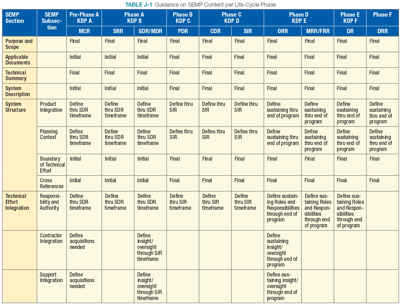
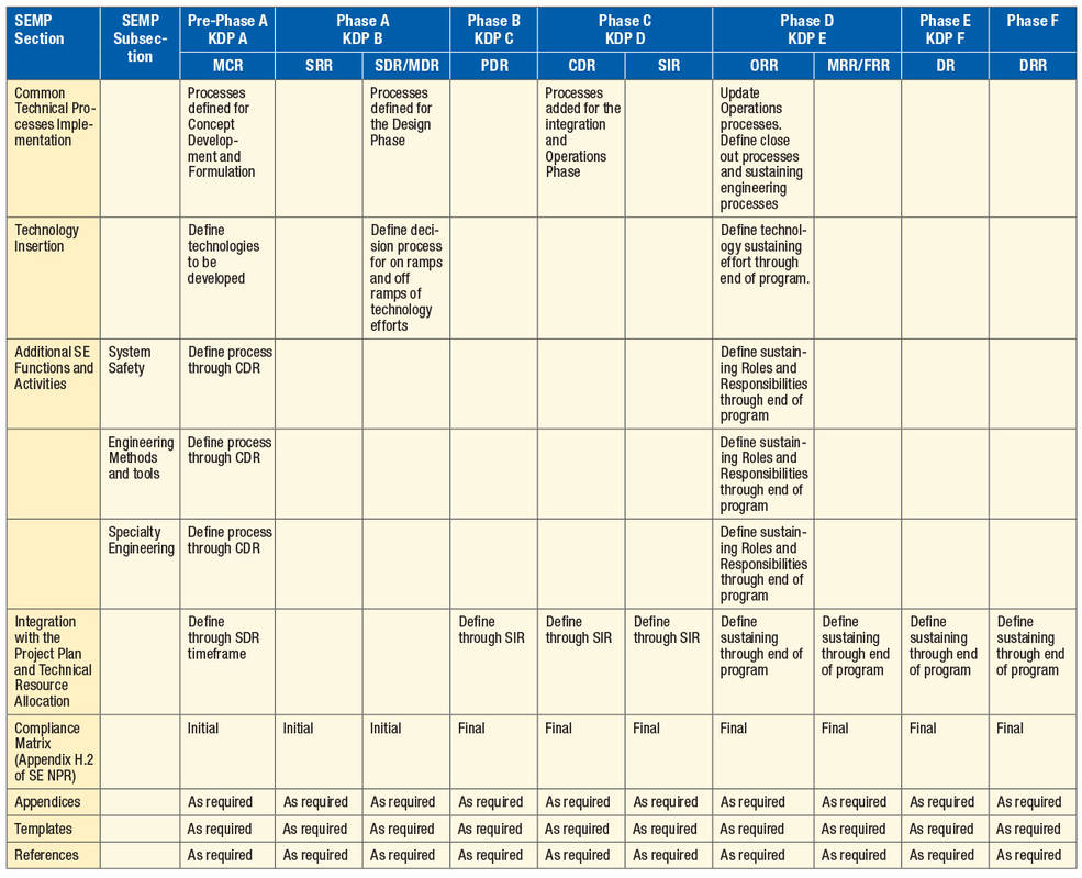
Appendix K: Technical Plans
The following table represents a typical expectation of maturity of some of the key technical plans developed during the SE processes. This example is for a space flight project. Requirements for work product maturity can be found in the governing PM document (i.e., NPR 7120.5) for the associated type of project.
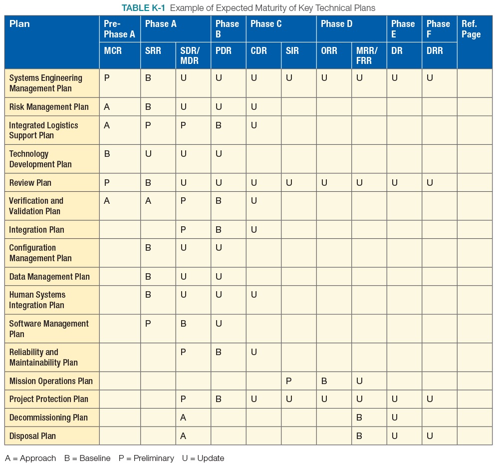
Appendix L: Interface Requirements Document Outline
1.0 Introduction
1.1 Purpose and Scope
State the purpose of this document and briefly identify the interface to be defined. (For example, “This IRD defines and controls the interface(s) requirements between ______ and ______.”)
1.2 Precedence
Define the relationship of this document to other program documents and specify which is controlling in the event of a conflict.
1.3 Responsibility and Change Authority
State the responsibilities of the interfacing organizations for development of this document and its contents. Define document approval authority (including change approval authority).
2.0 Documents
2.1 Applicable Documents
List binding documents that are invoked to the extent specified in this IRD. The latest revision or most recent version should be listed. Documents and requirements imposed by higher-level documents (higher order of precedence) should not be repeated.
2.2 Reference Documents
List any document that is referenced in the text in this subsection.
3.0 Interfaces
3.1 General
In the subsections that follow, provide the detailed description, responsibilities, coordinate systems, and numerical requirements as they relate to the interface plane.
3.1.1 Interface Description
Describe the interface as defined in the system specification. Use tables, figures, or drawings as appropriate.
3.1.2 Interface Responsibilities
Define interface hardware and interface boundary responsibilities to depict the interface plane. Use tables, figures, or drawings as appropriate.
3.1.3 Coordinate Systems
Define the coordinate system used for interface requirements on each side of the interface. Use tables, figures, or drawings as appropriate.
3.1.4 Engineering Units, Tolerances, and Conversion
Define the measurement units along with tolerances. If required, define the conversion between measurement systems.
3.2 Interface Requirements
In the subsections that follow, define structural limiting values at the interface, such as interface loads, forcing functions, and dynamic conditions. Define the interface requirements on each side of the interface plane.
3.2.1 Mass Properties
Define the derived interface requirements based on the allocated requirements contained in the applicable specification pertaining to that side of the interface. For example, this subsection should cover the mass of the element.
3.2.2 Structural/Mechanical
Define the derived interface requirements based on the allocated requirements contained in the applicable specification pertaining to that side of the interface. For example, this subsection should cover attachment, stiffness, latching, and mechanisms.
3.2.3 Fluid
Define the derived interface requirements based on the allocated requirements contained in the applicable specification pertaining to that side of the interface. For example, this subsection should cover fluid areas such as thermal control, O2 and N2, potable and waste water, fuel cell water, and atmospheric sampling.
3.2.4 Electrical (Power)
Define the derived interface requirements based on the allocated requirements contained in the applicable specification pertaining to that side of the interface. For example, this subsection should cover various electric current, voltage, wattage, and resistance levels.
3.2.5 Electronic (Signal)
Define the derived interface requirements based on the allocated requirements contained in the applicable specification pertaining to that side of the interface. For example, this subsection should cover various signal types such as audio, video, command data handling, and navigation.
3.2.6 Software and Data
Define the derived interface requirements based on the allocated requirements contained in the applicable specification pertaining to that side of the interface. For example, this subsection should cover various data standards, message timing, protocols, error detection/correction, functions, initialization, and status.
3.2.7 Environments
Define the derived interface requirements based on the allocated requirements contained in the applicable specification pertaining to that side of the interface. For example, cover the dynamic envelope measures of the element in English units or the metric equivalent on this side of the interface.
3.2.7.1 Electromagnetic Effects
3.2.7.1.a Electromagnetic Compatibility
Define the appropriate electromagnetic compatibility requirements. For example, the end-item-1-to-end-item-2 interface shall meet the requirements [to be determined] of systems requirements for electromagnetic compatibility.
3.2.7.1.b Electromagnetic Interference
Define the appropriate electromagnetic interference requirements. For example, the end-item-1-to-end-item-2 interface shall meet the requirements [to be determined] of electromagnetic emission and susceptibility requirements for electromagnetic compatibility.
3.2.7.1.c Grounding
Define the appropriate grounding requirements. For example, the end-item-1-to-end-item-2 interface shall meet the requirements [to be determined] of grounding requirements.
3.2.7.1.d Bonding
Define the appropriate bonding requirements. For example, the end-item-1-to-end-item-2 structural/mechanical interface shall meet the requirements [to be determined] of electrical bonding requirements.
3.2.7.1.e Cable and Wire Design
Define the appropriate cable and wire design requirements. For example, the end-item-1-to-end-item-2 cable and wire interface shall meet the requirements [to be determined] of cable/wire design and control requirements for electromagnetic compatibility.
3.2.7.2 Acoustic
Define the appropriate acoustics requirements. Define the acoustic noise levels on each side of the interface in accordance with program or project requirements.
3.2.7.3 Structural Loads
Define the appropriate structural loads requirements. Define the mated loads that each end item should accommodate.
3.2.7.4 Vibroacoustics
Define the appropriate vibroacoustics requirements. Define the vibroacoustic loads that each end item should accommodate.
3.2.7.5 Human Operability
Define the appropriate human interface requirements. Define the human-centered design considerations, constraints, and capabilities that each end item should accommodate.
3.2.8 Other Types of Interface Requirements
Define other types of unique interface requirements that may be applicable.
Appendix M: CM Plan Outline
A comprehensive Configuration Management (CM) Plan that reflects efficient application of configuration management principles and practices would normally include the following topics:
- General product definition and scope
- Description of CM activities and procedures for each major CM function
- Organization, roles, responsibilities, and resources
- Definitions of terms
- Programmatic and organizational interfaces
- Deliverables, milestones, and schedules
- Subcontract flow down requirements
The documented CM planning should be reevaluated following any significant change affecting the context and environment, e.g., changes in suppliers or supplier responsibilities, changes in diminishing manufacturing sources/part obsolescence, changes in resource availabilities, changes in customer contract, and changes in the product. CM planning should also be reviewed on a periodic basis to make sure that an organization’s application of CM functions is current.
For additional information regarding a CM Plan, refer to SAE EIA-649, Rev. B.
Appendix N: Guidance on Technical Peer Reviews/Inspections
This appendix has been removed. For additional guidance on how to perform technical peer reviews refer to Appendix N in the NASA Expanded Guidance for Systems Engineering at https://nen.nasa.gov/web/se/doc-repository.
Appendix O: Reserved
Appendix P: SOW Review Checklist
This appendix has been removed. For additional guidance on checklists for editorial and content review questions refer to Appendix P in the NASA Expanded Guidance for Systems Engineering at https://nen.nasa.gov/web/se/doc-repository.
Appendix Q: Reserved
Reserved
Appendix R: HSI Plan Content Outline
R.1 HSI Plan Overview
The Human Systems Integration (HSI) Plan documents the strategy for and planned implementation of HSI through a particular program’s/project’s life cycle. The intent of HSI is:
- To ensure the human elements of the total system are effectively integrated with hardware and software elements,
- To ensure all human capital required to develop and operate the system is accounted for in life cycle costing, and
- To ensure that the system is built to accommodate the characteristics of the user population that will operate, maintain, and support the system.
The HSI Plan is specific to a program or project and applies to NASA systems engineering per NPR 7123.1, NASA Systems Engineering Processes and Requirements. The HSI Plan should address the following:
- Roles and responsibilities for integration across HSI domains;
- Roles and responsibilities for coordinating integrated HSI domain inputs with the program team and stakeholders;
- HSI goals and deliverables for each phase of the life cycle;
- Entry and exit criteria with defined metrics for each phase, review, and milestone;
- Planned methods, tools, requirements, processes, and standards for conducting HSI;
- Strategies for identifying and resolving HSI risks; and
- Alignment strategy with the SEMP.
The party or parties responsible for program/project HSI implementation—e.g., an HSI integrator (or team)—should be identified by the program/project manager. The HSI integrator or team develops and maintains the HSI Plan with support from and coordination with the project manager and systems engineer.
Implementation of HSI on a program/project utilizes many of the tools and products already required by systems engineering; e.g., development of a ConOps, clear functional allocation across the elements of a system (hardware, software, and human), and the use of key performance measurements through the life cycle to validate and verify HSI’s effectiveness. It is not the intent of the HSI Plan or its implementation to duplicate other systems engineering plans or processes, but rather to define the uniquely HSI effort being made to ensure the human element is given equal consideration to hardware/software elements of a program/project.
R.2 HSI Plan Content Outline
Each program/project-specific HSI Plan should be tailored to fit the program/project’s size, scope, and purpose. The following is an example outline for a major program; e.g., space flight or aeronautics.
1.0 Introduction
1.1 Purpose
This section briefly identifies the ultimate objectives for this program/project’s HSI Plan. This section also introduces the intended implementers and users of this HSI Plan.
1.2 Scope
This section describes the overall scope of the HSI Plan’s role in documenting the strategy for and implementation of HSI. Overall, this section describes that the HSI Plan:
- Is a dynamic document that will be updated at key life cycle milestones.
- Is a planning and management guide that describes how HSI will be relevant to the program/project’s goals.
- Describes planned HSI methodology, tools, schedules, and deliverables.
- Identifies known program/project HSI issues and concerns and how their resolutions will be addressed.
- Defines program/project HSI organizational elements, roles, and responsibilities.
- May serve as an audit trail that documents HSI data sources, analyses, activities, trade studies, and decisions not captured in other program/project documentation.
1.3 Definitions
This section defines key HSI terms and references relevant program/project-specific terms.
2.0 Applicable Documents
This section lists all documents, references, and data sources that are invoked by HSI’s implementation on the program/project, that have a direct impact on HSI outcomes, and/or are impacted by the HSI effort.
3.0 HSI Objectives
3.1 System Description
This section describes the system, missions to be performed, expected operational environment(s), predecessor and/or legacy systems (and lessons learned), capability gaps, stage of development, etc. Additionally, reference should be made to the acquisition strategy for the system; e.g., if it is developed in-house within NASA or if major systems are intended for external procurement. The overall strategy for program integration should be referenced.
Note that this information is likely captured in other program/project documentation and can be referenced in the HSI Plan rather than repeated.
3.2 HSI Relevance
At a high level, this section describes HSI’s relevance to the program/project; i.e., how the HSI strategy will improve the program/project’s outcome. Known HSI challenges should be described along with mention of areas where human performance in the system’s operations is predicted to directly impact the probability of overall system performance and mission success.
4.0 HSI Strategy
4.1 HSI Strategy Summary
This section summarizes the HSI approaches, planning, management, and strategies for the program/project. It should describe how HSI products will be integrated across all HSI domains and how HSI inputs to program/project systems engineering and management processes contribute to system performance and help contain life cycle cost. This section (or Implementation Summary, Section 6 of this outline) should include a top-level schedule showing key HSI milestones.
4.2 HSI Domains
This section identifies the HSI domains applicable to the program/project including rationale for their relevance.
HSI RELEVANCE
Key Points
- Describe performance characteristics of the human elements known to be key drivers to a desired total system performance outcome.
- Describe the total system performance goals that require HSI support.
- Identify HSI concerns with legacy systems; e.g., if operations and logistics, manpower, skill selection, required training, logistics support, operators’ time, maintenance, and/or risks to safety and success exceeded expectations.
- Identify potential cost, schedule, risk, and trade-off concerns with the integration of human elements; e.g., quantity and skills of operators, maintainers, ground controllers, etc.
HSI STRATEGY
Key Points
- Identify critical program/project-specific HSI key decision points that will be used to track HSI implementation and success.
- Identify key enabling (and particularly, emerging) technologies and methodologies that may be overlooked in hardware/software systems trade studies but that may positively contribute to HSI implementation; e.g., in the areas of human performance, workload, personnel management, training, safety, and survivability.
- Describe HSI products that will be integrated with program/project systems engineering products, analyses, risks, trade studies, and activities.
- Describe efforts to ensure HSI will contribute in critically important Phase A and Pre-Phase A cost-effective design concept studies.
- Describe the plan and schedule for updating the HSI Plan through the program/project life cycle.
5.0 HSI Requirements, Organization, and Risk Management
5.1 HSI Requirements
This section references HSI requirements and standards applicable to the program/project and identifies the authority that invokes them; e.g., the NASA Procedural Requirements (NPR) document(s) that invoke applicability.
HSI DOMAINS
Key Points
- Identify any domain(s) associated with human performance capabilities and limitations whose integration into the program/project is likely to directly affect the probability of successful program/project outcome.
- An overview of processes to apply, document, validate, evaluate, and mitigate HSI domain knowledge and to integrate domain knowledge into integrated HSI inputs to program/project and systems engineering processes.
HSI REQUIREMENTS
Key Points
- Describe how HSI requirements that are invoked on the program/project contribute to mission success, affordability, operational effectiveness, and safety.
- HSI should include requirements that influence the system design to moderate manpower (operators, maintainers, system administrative, and support personnel), required skill sets (occupational specialties with high aptitude or skill requirements), and training requirements.
- Define the program/project-specific HSI strategy derived from NASA-STD-3001, NASA Space Flight Human-System Standard, Volume 2: Human Factors, Habitability, and Environmental Health, Standard 3.5 [V2 3005], “Human-Centered Design Process”, if applicable.
- Capture the development process and rationale for any program/project-specific requirements not derived from existing NASA standards. In particular, manpower, skill set, and training HSI requirements/ goals may be so program/project-specific as to not have NASA parent standards or requirements.
- Identify functional connections between HSI measures of effectiveness used to verify requirements and key performance measures used throughout the life cycle as indicators of overall HSI effectiveness.
5.2 HSI Organization, Roles, and Responsibilities
In this section, roles and responsibilities for program/project personnel assigned to facilitate and/or manage HSI tasks are defined; e.g., the HSI integrator (and/or team if required by NPR 8705.2). HSI integrator/team functional responsibilities to the program are described in addition to identification of organizational elements with HSI responsibilities. Describe the relationships between HSI integrator/team, stakeholders, engineering technical teams, and governing bodies (control boards).
5.2.1 HSI Organization
- Describe the HSI management structure for the program/project and identify its leaders and membership.
- Reference the organizational structure of the program (including industry partners) and describe the roles and responsibilities of the HSI integrator/team within that structure. Describe the HSI responsible party’s relationship to other teams, including those for systems engineering, logistics, risk management, test and evaluation, and requirements verification.
- Provide the relationship of responsible HSI personnel to NASA Technical Authorities (Engineering, Safety, and Health/Medical).
- Identify if the program/project requires NASA- (Government) and/or contractor-issued HSI Plans, and identify the responsible author(s). Describe how NASA’s HSI personnel will monitor and assess contractor HSI activities. For contractor-issued HSI Plans, identify requirements and processes for NASA oversight and evaluation of HSI efforts by subcontractors.
5.2.2 HSI Roles & Responsibilities
- Describe the HSI responsible personnel’s functional responsibilities to the program/project, addressing (as examples) the following:
- developing HSI program documentation;
- validating human performance requirements;
- conducting HSI analyses;
- designing human machine interfaces to provide the level of human performance required for operations, maintenance, and support, including conduct of training;
- describing the role of HSI experts in documenting and reporting the results from tests and evaluations.
- Define how collaboration will be performed within the HSI team, across program/project integrated product teams and with the program/project manager and systems engineer.
- Define how the HSI Plan and the SEMP will be kept aligned with each other.
- Define responsibility for maintaining and updating the HSI Plan through the program/project’s life cycle.
5.3 HSI Issue and Risk Processing
This section describes any HSI-unique processes for identifying and mitigating human system risks. HSI risks should be processed in the same manner and system as other program/project risks (technical, programmatic, schedule). However, human system risks may only be recognized by HSI domain and integration experts. Therefore, it may be important to document any unique procedures by which the program/project HSI integrator/team identifies, validates, prioritizes, and tracks the status of HSI-specific risks through the program/project risk management system. Management of HSI risks may be deemed the responsibility of the program’s/project’s HSI integrator/team in coordination with overall program/project risk management.
- Ensure that potential cost, schedule, risk, and trade-off concerns with the integration of human elements (operators, maintainers, ground controllers, etc.) with the total system are identified and mitigated.
- Ensure that safety, health, or survivability concerns that arise as the system design and implementation emerge are identified, tracked, and managed.
- Identify and describe any risks created by limitations on the overall program/project HSI effort (time, funding, insufficient availability of information, availability of expertise, etc.).
- Describe any unique attributes of the process by which the HSI integrator/team elevates HSI risks to program/project risks.
- Describe any HSI-unique aspects of how human system risk mitigation strategies are deemed effective.
6.0 HSI Implementation
6.1 HSI Implementation Summary
This section summarizes the HSI implementation approach by program/project phase. This section shows how an HSI strategy for the particular program/project is planned to be tactically enabled; i.e., establishment of HSI priorities; description of specific activities, tools, and products planned to ensure HSI objectives are met; application of technology in the achievement of HSI objectives; and an HSI risk processing strategy that identifies and mitigates technical and schedule concerns when they first arise.
6.2 HSI Activities and Products
In this section, map activities, resources, and products associated with planned HSI technical implementation to each systems engineering phase of the program/project. Consideration might be given to mapping the needs and products of each HSI domain by program/project phase. Examples of HSI activities include analyses, mockup/ prototype human-in-the-loop evaluations, simulation/ modeling, participation in design and design reviews, formative evaluations, technical interchanges, and trade studies. Examples of HSI resources include acquisition of unique/specific HSI skill sets and domain expertise, facilities, equipment, test articles, specific time allocations, etc.
When activities, products, or risks are tied to life cycle reviews, they should include a description of the HSI entrance and exit criteria to clearly define the boundaries of each phase, as well as resource limitations that may be associated with each activity or product (time, funding, data availability, etc.). A high-level, summary example listing of HSI activities, products, and known risk mitigations by life cycle phase is provided in Table R.2-1.
6.3 HSI Plan Update
The HSI Plan should be updated throughout the program/project’s life cycle management and systems engineering processes at key milestones. Milestones recommended for HSI Plan updates are listed in appendix G of NPR 7123.1, NASA Systems Engineering Processes and Requirements.
HSI IMPLEMENTATION
Key Points
- Relate HSI strategic objectives to the technical approaches planned for accomplishing these objectives.
- Overlay HSI milestones—e.g., requirements definition, verification, known trade studies, etc.—on the program/project schedule and highlight any inconsistencies, conflicts, or other expected schedule challenges.
- Describe how critical HSI key decision points will be dealt with as the program/project progresses through its life cycle. Indicate the plan to trace HSI key performance measures through the life cycle; i.e., from requirements to human/system functional performance allocations, through design, test, and operational readiness assessment.
- Identify HSI-unique systems engineering processes—e.g., verification using human-in-the-loop evaluations—that may require special coordination with program/project processes.
- As the system emerges, indicate plans to identify HSI lessons learned from the application of HSI on the program/project.
- Include a high-level summary of the resources required.
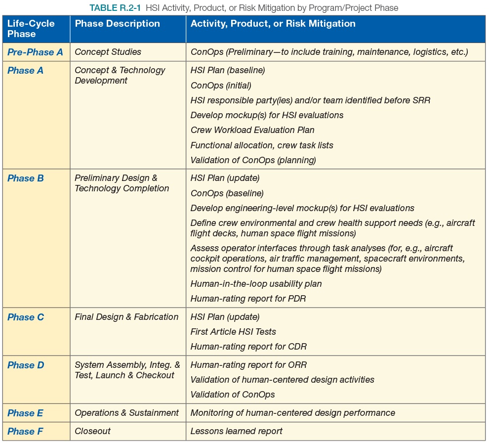
HSI PLAN UPDATES
Key points to be addressed in each update
- Identify the current program/project phase, the publication date of the last iteration of the HSI Plan, and the HSI Plan version number. Update the HSI Plan revision history.
- Describe the HSI entrance criteria for the current phase and describe any unfinished work prior to the current phase.
- Describe the HSI exit criteria for the current program/project phase and the work that must be accomplished to successfully complete the current program/project phase.
Appendix S: Concept of Operations Annotated Outline
This Concept of Operations (ConOps) annotated outline describes the type and sequence of information that should be contained in a ConOps, although the exact content and sequence will be a function of the type, size, and complexity of the project. The text in italics describes the type of information that would be provided in the associated subsection. Additional subsections should be added as necessary to fully describe the envisioned system.
Cover Page
Table of Contents
1.0 Introduction
1.1 Project Description
This section will provide a brief overview of the development activity and system context as delineated in the following two subsections.
1.1.1 Background
Summarize the conditions that created the need for the new system. Provide the high-level mission goals and objective of the system operation. Provide the rationale for the development of the system.
1.1.2 Assumptions and Constraints
State the basic assumptions and constraints in the development of the concept. For example, that some technology will be matured enough by the time the system is ready to be fielded, or that the system has to be provided by a certain date in order to accomplish the mission.
1.2 Overview of the Envisioned System
This section provides an executive summary overview of the envisioned system. A more detailed description will be provided in Section 3.0
1.2.1 Overview
This subsection provides a high-level overview of the system and its operation. Pictorials, graphics, videos, models, or other means may be used to provide this basic understanding of the concept.
1.2.2 System Scope
This section gives an estimate of the size and complexity of the system. It defines the system’s external interfaces and enabling systems. It describes what the project will encompass and what will lie outside of the project’s development.
2.0 Documents
2.1 Applicable Documents
This section lists all the documents, models, standards or other material that are applicable and some or all of which will form part of the requirements of the project.
2.2 Reference Documents
This section provides supplemental information that might be useful in understanding the system or its scenarios.
3.0 Description of Envisioned System
This section provides a more detailed description of the envisioned system and its operation as contained in the following subsections.
3.1 Needs, Goals and Objectives of Envisioned System
This section describes the needs, goals, and objectives as expectations for the system capabilities, behavior, and operations. It may also point to a separate document or model that contains the current up-to-date agreed-to expectations.
3.2 Overview of System and Key Elements
This section describes at a functional level the various elements that will make up the system, including the users and operators. These descriptions should be implementation free; that is, not specific to any implementation or design but rather a general description of what the system and its elements will be expected to do. Graphics, pictorials, videos, and models may be used to aid this description.
3.3 Interfaces
This section describes the interfaces of the system with any other systems that are external to the project. It may also include high-level interfaces between the major envisioned elements of the system. Interfaces may include mechanical, electrical, human user/operator, fluid, radio frequency, data, or other types of interactions.
3.4 Modes of Operations
This section describes the various modes or configurations that the system may need in order to accomplish its intended purpose throughout its life cycle. This may include modes needed in the development of the system, such as for testing or training, as well as various modes that will be needed during it operational and disposal phases.
3.5 Proposed Capabilities
This section describes the various capabilities that the envisioned system will provide. These capabilities cover the entire life cycle of the system’s operation, including special capabilities needed for the verification/validation of the system, its capabilities during its intended operations, and any special capabilities needed during the decommissioning or disposal process.
4.0 Physical Environment
This section should describe the environment that the system will be expected to perform in throughout its life cycle, including integration, tests, and transportation. This may include expected and off-nominal temperatures, pressures, radiation, winds, and other atmospheric, space, or aquatic conditions. A description of whether the system needs to operate, tolerate with degraded performance, or just survive in these conditions should be noted.
5.0 Support Environment
This section describes how the envisioned system will be supported after being fielded. This includes how operational planning will be performed and how commanding or other uploads will be determined and provided, as required. Discussions may include how the envisioned system would be maintained, repaired, replaced, it’s sparing philosophy, and how future upgrades may be performed. It may also include assumptions on the level of continued support from the design teams.
6.0 Operational Scenarios, Use Cases and/or Design Reference Missions
This section takes key scenarios, use cases, or DRM and discusses what the envisioned system provides or how it functions throughout that single-thread timeline.
The number of scenarios, use cases, or DRMs discussed should cover both nominal and off-nominal conditions and cover all expected functions and capabilities. A good practice is to label each of these scenarios to facilitate requirements traceability; e.g., [DRM-0100], [DRM- 0200], etc.
6.1 Nominal Conditions
These scenarios, use cases, or DRMs cover how the envisioned system will operate under normal circumstances where there are no problems or anomalies taking place.
6.2 Off-Nominal Conditions
These scenarios cover cases where some condition has occurred that will need the system to perform in a way that is different from normal. This would cover failures, low performance, unexpected environmental conditions, or operator errors. These scenarios should reveal any additional capabilities or safeguards that are needed in the system.
7.0 Impact Considerations
This section describes the potential impacts, both positive and negative, on the environment and other areas.
7.1 Environmental Impacts
Describes how the envisioned system could impact the environment of the local area, state, country, worldwide, space, and other planetary bodies as appropriate for the systems intended purpose. This includes the possibility of the generation of any orbital debris, potential contamination of other planetary bodies or atmosphere, and generation of hazardous wastes that will need disposal on earth and other factors. Impacts should cover the entire life cycle of the system from development through disposal.
7.2 Organizational Impacts
Describes how the envisioned system could impact existing or future organizational aspects. This would include the need for hiring specialists or operators, specialized or widespread training or retraining, and use of multiple organizations.
7.3 Scientific/Technical Impacts
This subsection describes the anticipated scientific or technical impact of a successful mission or deployment, what scientific questions will be answered, what knowledge gaps will be filled, and what services will be provided. If the purpose of this system is to improve operations or logistics instead of science, describe the anticipated impact of the system in those terms.
8.0 Risks and Potential Issues
This section describes any risks and potential issues associated with the development, operations or disposal of the envisioned system. Also includes concerns/risks with the project schedule, staffing support, or implementation approach. Allocate subsections as needed for each risk or issue consideration. Pay special attention to closeout issues at the end of the project.
Appendix A: Acronyms
This part lists each acronym used in the ConOps and spells it out.
Appendix B: Glossary of Terms
The part lists key terms used in the ConOps and provides a description of their meaning.
Appendix T: Systems Engineering in Phase E
T.1 Overview
In general, normal Phase E activities reflect a reduced emphasis on system design processes but a continued focus on product realization and technical management. Product realization process execution in Phase E takes the form of continued mission plan generation (and update), response to changing flight conditions (and occurrence of in-flight anomalies), and update of mission operations techniques, procedures, and guidelines based on operational experience gained. Technical management processes ensure that appropriate rigor and risk management practices are applied in the execution of the product realization processes.
Successful Phase E execution requires the prior establishment of mission operations capabilities in four (4) distinct categories: tools, processes, products, and trained personnel. These capabilities may be developed as separate entities, but need to be fused together in Phase E to form an end-to-end operational capability.
Although systems engineering activities and processes are constrained throughout the entire project life cycle, additional pressures exist in Phase E:
- Increased resource constraints: Even when additional funding or staffing can be secured, building new capabilities or training new personnel may require more time or effort than is available. Project budget and staffing profiles generally decrease at or before entry into Phase E, and the remaining personnel are typically focused on mission execution.
- Unforgiving schedule: Unlike pre-flight test activities, it may be difficult or even impossible to pause mission execution to deal with technical issues of a spacecraft in operation. It is typically difficult or impossible to truly pause mission execution after launch.
These factors must be addressed when considering activities that introduce change and risk during Phase E.
Note: When significant hardware or software changes are required in Phase E, the logical decomposition process may more closely resemble that exercised in earlier project phases. In such cases, it may be more appropriate to identify the modification as a new project executing in parallel—and coordinated with—the operating project.
T.2 Transition from Development to Operations
An effective transition from development to operations phases requires prior planning and coordination among stakeholders. This planning should focus not only on the effective transition of hardware and software systems into service but also on the effective transfer of knowledge, skills, experience, and processes into roles that support the needs of flight operations.
Development phase activities need to clearly and concisely document system knowledge in the form of operational techniques, characteristics, limits, and constraints—these are key inputs used by flight operations personnel in building operations tools and techniques. Phase D Integration and Test (I&T) activities share many common needs with Phase E operations activities. Without prior planning and agreement, however, similar products used in these two phases may be formatted so differently that one set cannot be used for both purposes. The associated product duplication is often unexpected and results in increased cost and schedule risk. Instead, system engineers should identify opportunities for product reuse early in the development process and establish common standards, formats, and content expectations to enable transition and reuse.
Similarly, the transfer of skills and experience should be managed through careful planning and placement of key personnel. In some cases, key design, integration, and test personnel may be transitioned into the mission operations team roles. In other cases, dedicated mission operations personnel may be assigned to shadow or assist other teams during Phase A–D activities. In both cases, assignees bring knowledge, skills, and experience into the flight operations environment. Management of this transition process can, however, be complex as these personnel may be considered key to both ongoing I&T and preparation for upcoming operations. Careful and early planning of personnel assignments and transitions is key to success in transferring skills and experience.
T.3 System Engineering Processes in Phase E
T.3.1 System Design Processes
In general, system design processes are complete well before the start of Phase E. However, events during operations may require that these processes be revisited in Phase E.
T.3.1.1 Stakeholder Expectations Definition
Stakeholder expectations should have been identified during development phase activities, including the definition of operations concepts and design reference missions. Central to this definition is a consensus on mission success criteria and the priority of all intended operations. The mission operations plan should state and address these stakeholder expectations with regard to risk management practices, planning flexibility and frequency of opportunities to update the plan, time to respond and time/scope of status communication, and other key parameters of mission execution. Additional detail in the form of operational guidelines and constraints should be incorporated in mission operations procedures and flight rules.
The Operations Readiness Review (ORR) should confirm that stakeholders accept the mission operations plan and operations implementation products.
However, it is possible for events in Phase E to require a reassessment of stakeholder expectations. Significant in-flight anomalies or scientific discoveries during flight operations may change the nature and goals of a mission. Mission systems engineers, mission operations managers, and program management need to remain engaged with stakeholders throughout Phase E to identify potential changes in expectations and to manage the acceptance or rejection of such changes during operations.
T.3.1.2 Technical Requirements Definition
New technical requirements and changes to existing requirements may be identified during operations as a result of:
- New understanding of system characteristics through flight experience;
- The occurrence of in-flight anomalies; or
- Changing mission goals or parameters (such as mission extension).
These changes or additions are generally handled as change requests to an operations baseline already under configuration management and possibly in use as part of ongoing flight operations. Such changes are more commonly directed to the ground segment or operations products (operational constraints, procedures, etc.). Flight software changes may also be considered, but flight hardware changes for anything other than human-tended spacecraft are rarely possible.
Technical requirement change review can be more challenging in Phase E as fewer resources are available to perform comprehensive review. Early and close involvement of Safety and Mission Assurance (SMA) representatives can be key in ensuring that proposed changes are appropriate and within the project’s allowable risk tolerance.
T.3.1.3 Logical Decomposition
In general, logical decomposition of mission operations functions is performed during development phases. Additional logical decomposition during operations is more often applied to the operations products: procedures, user interfaces, and operational constraints. The authors and users of these products are often the most qualified people to judge the appropriate decomposition of new or changed functionality as a series of procedures or similar products.
T.3.1.4 Design Solution Definition
Similar to logical decomposition, design solution definition tasks may be better addressed by those who develop and use the products. Minor modifications may be handled entirely within an operations team (with internal reviews), while larger changes or additions may warrant the involvement of program-level system engineers and Safety and Mission Assurance (SMA) personnel.
Scarcity of time and resources during Phase E can make implementation of these design solutions challenging. The design solution needs to take into account the availability of and constraints to resources.
T.3.1.5 Product Implementation
Personnel who implement mission operations products such as procedures and spacecraft command scripts should be trained and certified to the appropriate level of skill as defined by the project. Processes governing the update and creation of operations products should be in place and exercised prior to Phase E.
T.3.2 Product Realization Processes
Product realization processes in Phase E are typically executed by Configuration Management (CM) and test personnel. It is common for these people to be “shared resources;” i.e., personnel who fulfil other roles in addition to CM and test roles.
T.3.2.1 Product Integration
Product integration in Phase E generally involves bringing together multiple operations products—some preexisting and others new or modified—into a proposed update to the baseline mission operations capability.
The degree to which a set of products is integrated may vary based on the size and complexity of the project. Small projects may define a baseline—and update to that baseline—that spans the entire set of all operations products. Larger or more complex projects may choose to create logical baseline subsets divided along practical boundaries. In a geographically disperse set of separate mission operations Centers, for example, each Center may be initially integrated as a separate product. Similarly, the different functions within a single large control Center—planning, flight dynamics, command and control, etc.—may be established as separately baselined products. Ultimately, however, some method needs to be established to ensure that the product realization processes identify and assess all potential impacts of system changes.
T.3.2.2 Product Verification
Product verification in Phase E generally takes the form of unit tests of tools, data sets, procedures, and other items under simulated conditions. Such “thread tests” may exercise single specific tasks or functions. The fidelity of simulation required for verification varies with the nature and criticality of the product. Key characteristics to consider include:
- Runtime: Verification of products during flight operations may be significantly time constrained. Greater simulation fidelity can result in slower simulation performance. This slower performance may be acceptable for some verification activities but may be too constraining for others.
- Level of detail: Testing of simple plans and procedures may not require high-fidelity simulation of a system’s dynamics. For example, simple state change processes may be tested on relatively low-fidelity simulations. However, operational activities that involve dynamic system attributes – such as changes in pressure, temperature, or other physical properties may require testing with much higher-fidelity simulations.
- Level of integration: Some operations may impact only a single subsystem, while others can affect multiple systems or even the entire spacecraft.
- Environmental effects: Some operations products and procedures may be highly sensitive to environmental conditions, while others may not. For example, event sequences for atmospheric entry and deceleration may require accurate weather data. In contrast, simple system reconfiguration procedures may not be impacted by environmental conditions at all.
T.3.2.3 Product Validation
Product validation is generally executed through the use of products in integrated operational scenarios such as mission simulations, operational readiness tests, and/or spacecraft end-to-end tests. In these environments, a collection of products is used by a team of operators to simulate an operational activity or set of activities such as launch, activation, rendezvous, science operations, or Entry, Descent, and Landing (EDL). The integration of multiple team members and operations products provides the context necessary to determine if the product is appropriate and meets the true operations need.
T.3.2.4 Product Transition
Transition of new operational capabilities in Phase E is generally overseen by the mission operations manager or a Configuration Control Board (CCB) chaired by the mission operations manager or the project manager.
Proper transition management includes the inspection of product test (verification and validation) results as well as the readiness of the currently operating operations system to accept changes. Transition during Phase E can be particularly challenging as the personnel using these capabilities also need to change techniques, daily practices, or other behaviors as a result. Careful attention should be paid to planned operations, such as spacecraft maneuvers or other mission critical events and risks associated with performing product transition at times near such events.
T.3.3 Technical Management Processes
Technical management processes are generally a shared responsibility of the project manager and the mission operations manager. Clear agreement between these two parties is essential in ensuring that Phase E efforts are managed effectively.
T.3.3.1 Technical Planning
Technical planning in Phase E generally focuses on the management of scarce product development resources during mission execution. Key decision-makers, including the mission operations manager and lower operations team leads, need to review the benefits of a change against the resource cost to implement changes. Many resources are shared in Phase E – for example, product developers may also serve other real-time operations roles– and the additional workload placed on these resources should be viewed as a risk to be mitigated during operations.
T.3.3.2 Requirements Management
Requirements management during Phase E is similar in nature to pre-Phase E efforts. Although some streamlining may be implemented to reduce process overhead in Phase E, the core need to review and validate requirements remains. As most Phase E changes are derived from a clearly demonstrated need, program management may reduce or waive the need for complete requirements traceability analysis and documentation.
T.3.3.3 Interface Management
It is relatively uncommon for interfaces to change in Phase E, but this can occur when a software tool is modified or a new need is uncovered. Interface definitions should be managed in a manner similar to that used in other project phases.
T.3.3.4 Technical Risk Management
Managing technical risks during operations can be more challenging during Phase E than during other phases. New risks discovered during operations may be the result of system failures or changes in the surrounding environment. Where additional time may be available to assess and mitigate risk in other project phases, the nature of flight operations may limit the time over which risk management can be executed. For this reason, every project should develop a formal process for handling anomalies and managing risk during operations. This process should be exercised before flight, and decision-makers should be well versed in the process details.
T.3.3.5 Configuration Management
Effective and efficient Configuration Management (CM) is essential during operations. Critical operations materials, including procedures, plans, flight datasets, and technical reference material need to be secure, up to date, and easily accessed by those who make and enact mission critical decisions. CM systems—in their intended flight configuration—should be exercised as part of operational readiness tests to ensure that the systems, processes, and participants are flight-ready.
Access to such operations products is generally time-critical, and CM systems supporting that access should be managed accordingly. Scheduled maintenance or other “downtime” periods should be coordinated with flight operations plans to minimize the risk of data being inaccessible during critical activities.
T.3.3.6 Technical Data Management
Tools, procedures, and other infrastructure for Technical Data Management must be baselined, implemented, and verified prior to flight operations. Changes to these capabilities are rarely made during Phase E due to the high risk of data loss or reduction in operations efficiency when changing during operations.
Mandatory Technical Data Management infrastructure changes, when they occur, should be carefully reviewed by those who interact with the data on a regular basis. This includes not only operations personnel, but also engineering and science customers of that data.
T.3.3.7 Technical Assessment
Formal technical assessments during Phase E are typically focused on the upcoming execution of a specific operational activity such as launch, orbit entry, or decommissioning. Reviews executed while flight operations are in progress should be scoped to answer critical questions while not overburdening the project or operations team.
Technical Performance Measures (TPMs) in Phase E may differ significantly from those in other project phases. Phase E TPMs may focus on the accomplishment of mission events, the performance of the system in operation, and the ability of the operations team to support upcoming events.
T.3.3.8 Decision Analysis
The Phase E Decision Analysis Process is similar to that in other project phases but may emphasize different criteria. For example, the ability to change a schedule may be limited by the absolute timing of events such as an orbit entry or landing on a planetary surface. Cost trades may be more constrained by the inability to add trained personnel to support an activity. Technical trades may be limited by the inability to modify hardware in operation.