


![Request for Information – Potential [Placeholder for Prize]](https://assets.science.nasa.gov/dynamicimage/assets/science/psd/solar/2023/09/s/solarsystem_0.jpg?w=1024)


This chapter describes the activities in the product realization processes listed in Figure 2.1-1. The chapter is separated into sections corresponding to steps 5 through 9 listed in Figure 2.1-1. The processes within each step are discussed in terms of the inputs, the activities, and the outputs. Additional guidance is provided using examples that are relevant to NASA projects.
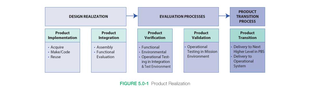
In the product realization side of the SE engine, five interdependent processes result in systems that meet the design specifications and stakeholder expectations. These products are produced, acquired, reused, or coded; integrated into higher level assemblies; verified against design specifications; validated against stakeholder expectations; and transitioned to the next level of the system. As has been mentioned in previous sections, products can be models and simulations, paper studies or proposals, or hardware and software. The type and level of product depends on the phase of the life cycle and the product’s specific objectives. But whatever the product, all should effectively use the processes to ensure the system meets the intended operational concept.
This effort starts with the technical team taking the output from the system design processes and using the appropriate crosscutting functions, such as data and configuration management, and technical assessments to make, buy, or reuse subsystems. Once these subsystems are realized, they should be integrated to the appropriate level as designated by the appropriate interface requirements. These products are then verified through the Technical Assessment Process to ensure that they are consistent with the technical data package and that “the product was built right.” Once consistency is achieved, the technical team validates the products against the stakeholder expectations to ensure that “the right product was built.” Upon successful completion of validation, the products are transitioned to the next level of the system. Figure 5.0-1 illustrates these processes.
This is an iterative and recursive process. Early in the life cycle, paper products, models, and simulations are run through the five realization processes. As the system matures and progresses through the life cycle, hardware and software products are run through these processes. It is important to detect as many errors and failures as possible at the lowest level of integration and early in the life cycle so that changes can be made through the design processes with minimum impact to the project.The next sections describe each of the five product realization processes and their associated products for a given NASA mission.
Product Realization Keys
- Define and execute production activities.
- Generate and manage requirements for off-the-shelf hardware/software products as for all other products.
- Understand the differences between verification testing and validation testing.
- Consider all customer, stakeholder, technical, programmatic, and safety requirements when evaluating the input necessary to achieve a successful product transition.
- Analyze for any potential incompatibilities with interfaces as early as possible.
- Completely understand and analyze all test data for trends and anomalies.
- Understand the limitations of the testing and any assumptions that are made.
- Ensure that a reused product meets the verification and validation required for the relevant system in which it is to be used, as opposed to relying on the original verification and validation it met for the system of its original use. Then ensure that it meets the same verification and validation as a purchased product or a built product. The “pedigree” of a reused product in its original application should not be relied upon in a different system, subsystem, or application.
The next sections describe each of the five product realization processes and their associated products for a given NASA mission.
5.1.1 Process Description
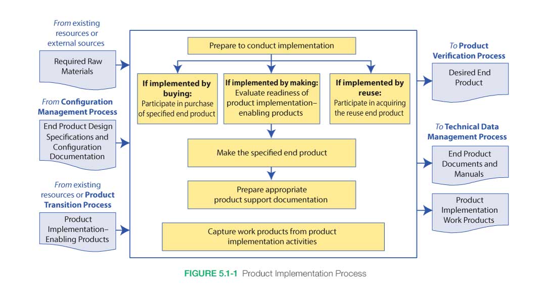
Figure 5.1-1 provides a typical flow diagram for the Product Implementation Process and identifies typical inputs, outputs, and activities to consider in addressing product implementation.
5.1.1.1 Inputs
Inputs to the Product Implementation Process depend primarily on the decision about whether the end product will be purchased, developed from scratch, or formed by reusing part or all of products from other projects. Typical inputs are shown in Figure 5.1-1.
- Inputs If Purchasing the End Product: If the decision was made to purchase part or all of the products for this project, the end product design specifications are obtained from the configuration management system as well as other applicable documents.
- Inputs If Making/Coding the End Product: For end products that will be made/coded by the technical team, the inputs will be the configuration-controlled design specifications, manufacturing plans, manufacturing processes, manufacturing procedures, and raw materials as provided to or purchased by the project.
- Inputs Needed If Reusing an End Product: For end products that will reuse part or all of products generated by other projects, the inputs may be the documentation associated with the product as well as the product itself. Care should be taken to ensure that these products will indeed meet the specifications and environments for this project. These would have been factors involved in the Decision Analysis Process to determine the make/buy/reuse decision.
- Enabling Products: These would be any enabling products necessary to make, code, purchase, or reuse the product (e.g., drilling fixtures, production facilities, production lines, software development facilities, software test facilities, system integration and test facilities).
5.1.1.2 Process Activities
Implementing the product can take one of three forms:
- Purchase/buy
- Make/code
- Reuse
These three forms will be discussed in the following subsections. Figure 5.1-1 shows what kind of inputs, outputs, and activities are performed during product implementation regardless of where in the product hierarchy or life cycle it is. These activities include preparing to conduct the implementation, purchasing/making/reusing the product, and capturing the product implementation work product. In some cases, implementing a product may have aspects of more than one of these forms (such as a build-to-print). In those cases, the appropriate aspects of the applicable forms are used.
5.1.1.2.1 Prepare to Conduct Implementation
Preparing to conduct the product implementation is a key first step regardless of what form of implementation has been selected. For complex projects, implementation strategy and detailed planning or procedures need to be developed and documented. For less complex projects, the implementation strategy and planning need to be discussed, approved, and documented as appropriate for the complexity of the project.
The documentation, specifications, and other inputs also need to be reviewed to ensure they are ready and at an appropriate level of detail to adequately complete the type of implementation form being employed and for the product life cycle phase. For example, if the “make” implementation form is being employed, the design specifications need to be reviewed to ensure they are at a design-to level that allows the product to be developed. If the product is to be bought as a pure Commercial Off-the-Shelf (COTS) item, the specifications need to be checked to make sure they adequately describe the vendor characteristics to narrow to a single make/model of their product line.
Finally, the availability and skills of personnel needed to conduct the implementation as well as the availability of any necessary raw materials, enabling products, or special services should also be reviewed. Any special training necessary for the personnel to perform their tasks needs to be performed by this time. This is a key part of the Acceptance Data Package.
5.1.1.2.2 Purchase, Make, or Reuse the Product
Purchase the Product
In the first case, the end product is to be purchased from a commercial or other vendor. Design/purchase specifications will have been generated during requirements development and provided as inputs. The technical team needs to review these specifications and ensure they are in a form adequate for the contract or purchase order. This may include the generation of contracts, Statements of Work (SOWs), requests for proposals, purchase orders, or other purchasing mechanisms. For major end products purchased from a vendor, the responsibilities of the Government and contractor team should be documented in the SEMP and Integration Plan. This will define, for example, whether NASA expects the vendor to provide a fully verified and validated product or whether the NASA technical team will be performing those duties. The team needs to work with the acquisition team to ensure the accuracy of the contract SOW or purchase order and to ensure that adequate documentation, certificates of compliance, or other specific needs are requested from the vendor.
For contracted purchases, as proposals come back from the vendors, the technical team should work with the contracting officer and participate in the review of the technical information and in the selection of the vendor that best meets the design requirements for acceptable cost and schedule.
As the purchased products arrive, the technical team should assist in the inspection of the delivered product and its accompanying documentation. The team should ensure that the requested product was indeed the one delivered, and that all necessary documentation, such as source code, operator manuals, certificates of compliance, safety information, or drawings have been received.
The NASA technical team should also ensure that any enabling products necessary to provide test, operations, maintenance, and disposal support for the product are also ready or provided as defined in the contract.
Depending on the strategy and roles/responsibilities of the vendor, a determination/analysis of the vendor’s verification and validation compliance may need to be reviewed. This may be done informally or formally as appropriate for the complexity of the product. For products that were verified and validated by the vendor, after ensuring that all work products from this phase have been captured, the product may be ready to enter the Product Transition Process to be delivered to the next higher level or to its final end user. For products that the technical team will verify and validate, the product will be ready for verification after ensuring that all work products for this phase have been captured.
Make/Code the Product
If the strategy is to make or code the product, the technical team should first ensure that the enabling products are ready. This may include ensuring all piece parts are available, drawings are complete and adequate, software design is complete and reviewed, machines to cut the material are available, interface specifications are approved, operators are trained and available, manufacturing and/or coding procedures/processes are ready, software personnel are trained and available to generate code, test fixtures are developed and ready to hold products while being generated, and software test cases are available and ready to begin model generation.
The product is then made or coded in accordance with the specified requirements, configuration documentation, and applicable standards. Software development must be consistent with NPR 7150.2, NASA Software Engineering Requirements. Throughout this process, the technical team should work with the quality organization to review, inspect, and discuss progress and status within the team and with higher levels of management as appropriate. Progress should be documented within the technical schedules. Peer reviews, audits, unit testing, code inspections, simulation checkout, and other techniques may be used to ensure the made or coded product is ready for the verification process. Some production and coding can also be separately contracted. This is sometimes pursued as a cost control feature providing motivation for the design contractor to keep the operations costs low and not roll costs into the operations phase of a long-term contract. This is also valuable when the design contractor is not well suited for long-term continuing production operations. Small projects and activities often use small manufacturing shops to fabricate the system or major portions and small software companies to code their software. In these cases, the production and software engineers may specify some portion of the hardware production or software coding and request the remaining portions, including as-built documentation, from the manufacturing or software provider. The specified portions are contained as part of the contract statement of work in these cases. The level of process control and information provided to or from the vendor is dependent on the criticality of the systems obtained. As production proceeds and components are produced, there is a need to establish a method (Material Review Boards (MRBs) are typically used for large projects) to review any nonconformance to specifications and disposition whether the components can be accepted, reworked, or scrapped and remade.
Reuse
If the strategy is to reuse a product that already exists, extreme care should be taken to ensure that the product is truly applicable to this project and for the intended uses and the environment in which it will be used. This should have been a major factor used in the decision strategy to make/buy/reuse. If the new environment is more extreme, requalification is needed for the component or system. Design factors of safety, margins, and other required design and construction standards should also be assessed. If the program/project requires higher factor of safety or margins, the component may not be usable or a waiver may have to be approved.
The documentation available (e.g., as-built documentation, user’s guides, operations manuals, discrepancy reports, waivers and deviations) from the reuse product should be reviewed by the technical team so that they can become completely familiar with the product and ensure it will meet the requirements in the intended environment. Any supporting manuals, drawings, or other documentation available should also be gathered.
The availability of any supporting or enabling products or infrastructure needed to complete the fabrication, coding, testing, analysis, verification, validation, or shipping of the product needs to be determined. Supporting products may be found in product manufacturing plans, processes, and procedures. If any of these products or services are lacking, they will need to be developed or arranged for before progressing to the next phase.
Special arrangements may need to be made or forms such as nondisclosure agreements may need to be acquired before the reuse product can be received.
A reused product often needs to undergo the same verification and validation as a purchased product or a built product. Relying on prior verification and validation should only be considered if the product’s verification and validation documentation meets or exceeds the verification, validation, and documentation requirements of the current project and the documentation demonstrates that the product was verified and validated against equivalent requirements (including environments) and expectations. The savings gained from reuse is not necessarily from reduced acceptance-level testing of the flight products, but possibly elimination of the need to fully requalify the item (if all elements are the same, including the environment and operation), elimination of the need to specify all of the internal requirements such as printed circuit board specifications or material requirements, reduced internal data products, or the confidence that the item will pass acceptance test and will not require rework.
5.1.1.2.3 Capture Work Products
Regardless of what implementation form was selected, all work products from the make/buy/reuse process should be captured, including as-built design drawings, design documentation, design models, code listings, model descriptions, procedures used, operator manuals, maintenance manuals, or other documentation as appropriate.
5.1.1.3 Outputs
- End Product for Verification: Unless the vendor performs verification, the made/coded, purchased, or reused end product in a form appropriate for the life cycle phase is provided for the verification process. The form of the end product is a function of the life cycle phase and the placement within the system structure (the form of the end product could be hardware, software, model, prototype, first article for test, or single operational article or multiple production articles).
- End Product Documents and Manuals: Appropriate documentation is also delivered with the end product to the verification process and to the technical data management process. Documentation may include applicable as-built design drawings; close out photos; operation, user, maintenance, or training manuals; applicable baseline documents (configuration information such as as-built specifications or stakeholder expectations); certificates of compliance; or other vendor documentation.
- Product Implementation Work Products: Any additional work products providing reports, records, lesson learned, assumptions, updated CM products, and other outcomes of these activities.
The process is complete when the following activities have been accomplished:
- End products are fabricated, purchased, or reuse modules are acquired.
- End products are reviewed, checked, and ready for verification.
- Procedures, decisions, assumptions, anomalies, corrective actions, lessons learned, etc., resulting from the make/buy/reuse are recorded.
5.1.2 Product Implementation Guidance
Refer to Section 5.1.2 in the NASA Expanded Guidance for Systems Engineering at https://nen.nasa.gov/web/se/doc-repository for additional guidance on:
- buying off-the-shelf products and
- the need to consider the heritage of products.
Product integration is a key activity of the systems engineer. Product integration is the engineering of the subsystem interactions and their interactions with the system environments (both natural and induced). Also in this process, lower-level products are assembled into higher-level products and checked to make sure that the integrated product functions properly and that there are no adverse emergent behaviors. This integration begins during concept definition and continues throughout the system life cycle. Integration involves several activities focused on the interactions of the subsystems and environments. These include system analysis to define and understand the interactions, development testing including qualification testing, and integration with external systems (e.g., launch operations centers, space vehicles, mission operations centers, flight control centers, and aircraft) and objects (i.e., planetary bodies or structures). To accomplish this integration, the systems engineer is active in integrating the different discipline and design teams to ensure system and environmental interactions are being properly balanced by the differing design teams. The result of a well-integrated and balanced system is an elegant design and operation.
Integration begins with concept development, ensuring that the system concept has all necessary functions and major elements and that the induced and natural environment domains in which the system is expected to operate are all identified. Integration continues during requirements development, ensuring that all system and environmental requirements are compatible and that the system has a proper balance of functional utility to produce a robust and efficient system. Interfaces are defined in this phase and are the pathway of system interactions. Interfaces include mechanical (i.e., structure, loads), fluids, thermal, electrical, data, logical (i.e., algorithms and software), and human. These interfaces may include support for assembly, maintenance, and testing functions in addition to the system main performance functions. The interactions that occur through all of these interfaces can be subtle and complex, leading to both intended and unintended consequences. All of these interactions need to be engineered to produce an elegant and balanced system.
Integration during the design phase continues the engineering of these interactions and requires constant analysis and management of the subsystem functions and the subsystem interactions between themselves and with their environments. Analysis of the system interactions and managing the balance of the system is the central function of the systems engineer during the design process. The system needs to create and maintain a balance between the subsystems, optimizing the system performance over any one subsystem to achieve an elegant and efficient design. The design phase often involves development testing at the component, assembly, or system level. This is a key source of data on system interactions, and the developmental test program should be structured to include subsystem interactions, human-in-the-loop evaluations, and environmental interaction test data as appropriate.
Integration continues during the operations phase, bringing together the system hardware, software, and human operators to perform the mission. The interactions between these three integrated natures of the system need to be managed throughout development and into operations for mission success. The systems engineer, program manager, and the operations team (including the flight crew from crewed missions) need to work together to perform this management. The systems engineer is not only cognizant of these operations team interactions, but is also involved in the design responses and updates to changes in mission parameters and unintended consequences (through fault management).
Finally, integration or de-integration occurs during system closeout (i.e., decommissioning and disposal). The system capabilities to support de-integration and/or disposal need to be engineered into the system from the concept definition phase. The closeout phase involves the safe disposal of flight assets consistent with U.S. policy and law and international treaties. This disposal can involve the safe reentry and recovery or impact in the ocean, impact on the moon, or solar trajectory. This can also involve the disassembly or repurposing of terrestrial equipment used in manufacturing, assembly, launch, and flight operations. Dispositioning of recovered flight assets also occurs during this phase. Capture of system data and archiving for use in future analysis also occurs. In all of these activities, the systems engineer is involved in ensuring a smooth and logical disassembly of the system and associated program assets.
The Product Integration Process applies not only to hardware and software systems but also to service-oriented solutions, requirements, specifications, plans, and concepts. The ultimate purpose of product integration is to ensure that the system elements function as a whole.
Product integration involves many activities that need to be planned early in the program or project in order to effectively and timely accomplish the integration. Some integration activities (such as system tests) can require many years of work and costs that need to be identified and approved through the budget cycles. An integration plan should be developed and documented to capture this planning. Small projects and activities may be able to include this as part of their SEMP. Some activities may have their integration plans captured under the integration plan of the sponsoring flight program or R&T program. Larger programs and projects need to have a separate integration plan to clearly lay out the complex analysis and tests that need to occur. An example outline for a separate integration plan is provided in Appendix H.
During project closeout, a separate closeout plan should be produced describing the decommissioning and disposal of program assets. (For example, see National Space Transportation System (NSTS) 60576, Space Shuttle Program, Transition Management Plan). For smaller projects and activities, particularly with short life cycles (i.e., short mission durations), the closeout plans may be contained in the SEMP.
5.2.1 Process Description
Figure 5.2-1 provides a typical flow diagram for the Product Integration Process and identifies typical inputs, outputs, and activities to consider in addressing product integration. The activities of the Product Integration Process are truncated to indicate the action and object of the action.

5.2.1.1 Inputs
- Lower-level products to be integrated: These are the products developed in the previous lower-level tier in the product hierarchy. These products will be integrated/assembled to generate the product for this product layer.
- End product design specifications and configuration documentation: These are the specifications, Interface Control Documents (ICDs), drawings, integration plan, procedures, or other documentation or models needed to perform the integration including documentation for each of the lower-level products to be integrated.
- Product integration-enabling products: These would include any enabling products, such as holding fixtures, necessary to successfully integrate the lower-level products to create the end product for this product layer.
5.2.1.2 Process Activities
This subsection addresses the approach to the implementation of the Product Integration Process, including the activities required to support the process. The basic tasks that need to be established involve the management of internal and external interactions of the various levels of products and operator tasks to support product integration and are as follows:
5.2.1.2.1 Prepare to Conduct Product Integration
Prepare to conduct product integration by (1) reviewing the product integration strategy/plan (see Section 6.1.2.4.4), generating detailed planning for the integration, and developing integration sequences and procedures; and (2) determining whether the product configuration documentation is adequate to conduct the type of product integration applicable for the product life cycle phase, location of the product in the system structure, and management phase success criteria.
An integration strategy is developed and documented in an integration plan. This plan, as well as supporting documentation, identifies the optimal sequence of receipt, assembly, and activation of the various components that make up the system. This strategy should use technical, cost, and schedule factors to ensure an assembly, activation, and loading sequence that minimizes cost and assembly difficulties. The larger or more complex the system or the more delicate the element, the more critical the proper sequence becomes, as small changes can cause large impacts on project results.
The optimal sequence of assembly is built from the bottom up as components become sub-elements, elements, and subsystems, each of which should be checked prior to fitting it into the next higher assembly. The sequence will encompass any effort needed to establish and equip the assembly facilities; e.g., raised floor, hoists, jigs, test equipment, input/output, and power connections. Once established, the sequence should be periodically reviewed to ensure that variations in production and delivery schedules have not had an adverse impact on the sequence or compromised the factors on which earlier decisions were made.
5.2.1.2.2 Obtain Lower-Level Products for Assembly and Integration
Each of the lower-level products that is needed for assembly and integration is obtained from the transitioning lower-level product owners or a storage facility as appropriate. Received products should be inspected to ensure no damages occurred during the transitioning process.
5.2.1.2.3 Confirm That Received Products Have Been Validated
Confirm that the received products that are to be assembled and integrated have been validated to demonstrate that the individual products satisfy the agreed-to set of stakeholder expectations, including interface requirements. This validation can be conducted by the receiving organization or by the providing organization if fully documented or witnessed by the receiving representative.
5.2.1.2.4 Prepare the Integration Environment for Assembly and Integration
Prepare the integration environment in which assembly and integration will take place, including evaluating the readiness of the product integration-enabling products and the assigned workforce. These enabling products may include facilities, equipment jigs, tooling, and assembly/production lines. The integration environment includes test equipment, simulators, models, storage areas, and recording devices.
5.2.1.2.5 Assemble and Integrate the Received Products into the Desired End Product
Assemble and integrate the received products into the desired end product in accordance with the specified requirements, configuration documentation, interface requirements, applicable standards, and integration sequencing and procedures. This activity includes managing, evaluating, and controlling physical, functional, and data interfaces among the products being integrated.
Functional testing of the assembled or integrated unit is conducted to ensure that assembly is ready to enter verification testing and ready to be integrated into the next level. Typically, all or key representative functions are checked to ensure that the assembled system is functioning as expected. Formal product verification and validation will be performed in the next process.
5.2.1.2.6 Prepare Appropriate Product Support
Documentation
Prepare appropriate product support documentation, such as special procedures for performing product verification and product validation. Drawings or accurate models of the assembled system are developed and confirmed to be representative of the assembled system.
5.2.1.2.7 Capture Product Integration Work Products
Capture work products and related information generated while performing the Product Integration Process activities. These work products include system models, system analysis data and assessment reports, derived requirements, the procedures that were used in the assembly, decisions made and supporting rationale, assumptions that were made, identified anomalies and associated corrective actions, lessons learned in performing the assembly, and updated product configuration and support documentation.
5.2.1.3 Outputs
The following are typical outputs from this process and destinations for the products from this process:
- Integrated product(s) with all system interactions identified and properly balanced.
- Documentation and manuals, including system analysis models, data, and reports supporting flight-readiness rationale and available for future analysis during the operation of the system in the mission-execution phase.
- Work products, including reports, records, and non-deliverable outcomes of product integration activities (to support the Technical Data Management Process); integration strategy document; assembly/check area drawings; system/component documentation sequences and rationale for selected assemblies; interface management documentation; personnel requirements; special handling requirements; system documentation; shipping schedules; test equipment and drivers’ requirements; emulator requirements; and identification of limitations for both hardware and software.
5.2.2 Product Integration Guidance
Refer to Section 5.2.2 in the NASA Expanded Guidance for Systems Engineering at https://nen.nasa.gov/web/se/doc-repository for additional guidance on:
- product integration strategies,
- the relationship to product implementation,
- product integration support,
- product integration of the design solution,
- system analysis, and
- interface system integration.
The Product Verification Process is the first of the verification and validation processes conducted on an end product. As used in the context of the systems engineering common technical processes, a product is one provided by either the Product Implementation Process or the Product Integration Process in a form suitable for meeting applicable life cycle phase success criteria. Realization is the act of implementing, integrating, verifying, validating, and transitioning the end product for use at the next level up of the system structure or to the customer. At this point, the end product can be referred to as a “realized product” or “realized end product.”
Product verification proves that an end product (whether built, coded, bought, or reused) for any element within the system structure conforms to its requirements or specifications. Such specifications and other design description documentation establish the configuration baseline of that product, which may have to be modified at a later time. Without a verified baseline and appropriate configuration controls, such later modifications could be costly or cause major performance problems.
From a process perspective, product verification and validation may be similar in nature, but the objectives are fundamentally different. A customer is interested in whether the end product provided will do what the customer intended within the environment of use. Examination of this condition is validation. Simply put, the Product Verification Process answers the critical question, “Was the end product realized right?” The Product Validation Process addresses the equally critical question, “Was the right end product realized?” When cost effective and warranted by analysis, the expense of validation testing alone can be mitigated by combining tests to perform verification and validation simultaneously.
The outcome of the Product Verification Process is confirmation that the end product, whether achieved by implementation or integration, conforms to its specified requirements, i.e., verification of the end product. This subsection discusses the process activities, inputs, outcomes, and potential product deficiencies.
Differences Between Verification and Validation Testing
Testing is a detailed evaluation method of both verification and validation Verification Testing:
Verification Testing: Verification testing relates back to the approved requirements set (such as an SRD) and can be performed at different stages in the product life cycle. Verification tests are the official “for the record” testing performed on a system or element to show that it meets its allocated requirements or specifications including physical and functional interfaces. Verification tests use instrumentation and measurements and are generally accomplished by engineers, technicians, or operator-maintainer test personnel in a controlled environment to facilitate failure analysis.
Validation Testing: Validation relates back to the ConOps document. Validation testing is conducted under realistic conditions (or simulated conditions) on any end product to determine the effectiveness and suitability of the product for use in mission operations by typical users and to evaluate the results of such tests. It ensures that the system is operating as expected when placed in a realistic environment.
5.3.1 Process Description
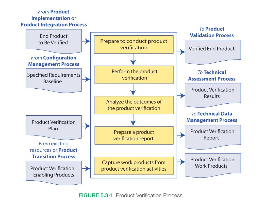
Figure 5.3-1, taken from NPR 7123.1, provides a typical flow diagram for the Product Verification Process and identifies typical inputs, outputs, and activities to consider in addressing product verification.
5.3.1.1 Inputs
Key inputs to the process are:
- The product to be verified: This product will have been transitioned from either the Product Implementation Process or the Product Integration Process. The product will likely have been through at least a functional test to ensure it was assembled correctly. Any supporting documentation should be supplied with the product.
- Verification plan: This plan will have been developed under the Technical Planning Process and baselined before entering this verification.
- Specified requirements baseline: These are the requirements that have been identified to be verified for this product. Acceptance criteria should have been identified for each requirement to be verified.
- Enabling products: Any other products needed to perform the Product Verification Process. This may include test fixtures and support equipment.
Additional work products such as the ConOps, mission needs and goals, interface control drawings, testing standards and policies, and Agency standards and policies may also be needed to put verification activities into context.
Differences Between Verification, Qualification, Acceptance and Certification
Verification: Verification is a formal process, using the method of test, analysis, inspection or demonstration, to confirm that a system and its associated hardware and software components satisfy all specified requirements. The Verification program is performed once regardless of how many flight units may be generated (as long as the design doesn’t change).
Qualification: Qualification activities are performed to ensure that the flight unit design will meet functional and performance requirements in anticipated environmental conditions. A subset of the verification program is performed at the extremes of the environmental envelope and will ensure the design will operate properly with the expected margins. Qualification is performed once regardless of how many flight units may be generated (as long as the design doesn’t change).
Acceptance: smaller subset of the verification program is selected as criteria for the acceptance program. The selected Acceptance activities are performed on each of the flight units as they are manufactured and readied for flight/use. An Acceptance Data Package is prepared for each of the flight units and shipped with the unit. The acceptance test/analysis criteria are selected to show that the manufacturing/workmanship of the unit conforms to the design that was previously verified/qualified. Acceptance testing is performed for each flight unit produced.
Certification: Certification is the audit process by which the body of evidence that results from the verification activities and other activities are provided to the appropriate certifying authority to indicate the design is certified for flight/use. The Certification activity is performed once regardless of how many flight units may be generated.
5.3.1.2 Process Activities
There are five major activities in the Product Verification Process: (1) prepare to conduct product verification; (2) perform verification; (3) analyze verification results; (4) preparing a product verification report; and (5) capture work products generated during the verification activities.
Product Verification is often performed by the developer that produced the end product with participation of the end user and customer. Quality Assurance (QA) personnel are also critical in the verification planning and execution activities.
A verification approach should be adapted (tailored) to the project it supports. The project manager and systems engineer should work with the verification lead engineer to develop a verification approach and plan the activities. Many factors need to be considered in developing this approach and the subsequent verification program. These factors include:
- Project type, especially for flight projects. Verification activities and timing depend on the following:
- The type of flight article involved (e.g., an experiment, payload, or launch vehicle).
- For missions required to follow NPR 7120.5, NASA Space Flight Program and Project Management Requirements, NASA payload classification (NPR 8705.4, Risk Classification for NASA Payloads) guidelines are intended to serve as a starting point for establishing the formality of verification approaches that can be adapted to the needs of a specific project based on the “A–D” payload classification. Further flexibility is imparted to projects following NPR 7120.8, NASA Research and Technology Program and Project Management Requirements.
- Project cost and schedule implications. Verification activities can be significant drivers of a project’s cost and schedule, and these implications should be considered early in the development of the verification plan. Trade studies should be performed early in the life cycle to support decisions about verification methods and types and the selection of facility capabilities and locations. For example, a trade study might be made to decide between performing a test at a centralized facility or at several decentralized locations.
- Risk management should be considered in the development of the verification approach. Qualitative risk assessments and quantitative risk analyses (e.g., a Failure Mode and Effects Analysis (FMEA)) often identify new concerns that can be mitigated by additional verifications, thus increasing the extent of verification activities. Other risk assessments contribute to trade studies that determine the preferred methods of verification to be used and when those methods should be performed. For example, a trade might be made between performing a model test versus determining model characteristics by a less costly but less revealing analysis. The project manager/systems engineer should determine what risks are acceptable in terms of the project’s cost and schedule.
- Availability of verification facilities/sites and transportation assets to move an article from one location to another (when needed). This requires coordination with the Integrated Logistics Support (ILS) engineer.
- Availability of appropriately trained users for interaction with systems having human interfaces.
- Acquisition strategy; i.e., in-house development or system contract. A NASA field Center can often shape a contractor’s verification process through the project’s SOW.
- Degree of design heritage and hardware/software reuse.
5.3.1.2.1 Product Verification Preparation
In preparation for verification, the verification plan and the specified requirements are collected, reviewed, and confirmed. The product to be verified is obtained (output from the Product Implementation Process or the Product Integration Process) along with any enabling products, such as those representing external interfacing products and support resources (including personnel) that are necessary for verification. Procedures capturing detailed step-by-step activities and based on the verification type and methods are finalized and approved. Development of procedures typically begins during the design phase of the project life cycle and matures as the design is matured. The verification environment is considered as part of procedure development. Operational scenarios are assessed to explore all possible verification activities to be performed. The final element is preparation of the verification environment; e.g., facilities, equipment, tools, measuring devices, and climatic conditions.
When operator or other user interaction is involved, it is important to ensure that humans are properly represented in the verification activities. This includes physical size, skills, knowledge, training, clothing, special gear, and tools. Note: Testing that includes representatives of the human in the system is often referred to as “human-in-the-loop” testing.
Note: Depending on the nature of the verification effort and the life cycle phase the program is in, some type of review to assess readiness for verification (as well as validation later) is typically held. In earlier phases of the life cycle, these Test Readiness Reviews (TRRs) may be held informally; in later phases of the life cycle, this review may become a more formal event. TRRs and other technical reviews are an activity of the Technical Assessment Process.
On most projects, a number of TRRs with tailored entrance/success criteria are held to assess the readiness and availability of test ranges, test facilities, trained testers, instrumentation, integration labs, support equipment, and other enabling products.
Peer reviews are additional reviews that may be conducted formally or informally to ensure readiness for verification (as well as the results of the verification process). Guidelines for conducting a peer review are discussed in Section 6.7.2.4.5.
Methods of Verification
Analysis: The use of mathematical modeling and analytical techniques to predict the suitability of a design to stakeholder expectations based on calculated data or data derived from lower system structure end product verifications. Analysis is generally used when a prototype; engineering model; or fabricated, assembled, and integrated product is not available. Analysis includes the use of modeling and simulation as analytical tools. A model is a mathematical representation of reality. A simulation is the manipulation of a model. Analysis can include verification by similarity of a heritage product.
Demonstration: Showing that the use of an end product achieves the individual specified requirement. It is generally a basic confirmation of performance capability, differentiated from testing by the lack of detailed data gathering. Demonstrations can involve the use of physical models or mock-ups; for example, a requirement that all controls shall be reachable by the pilot could be verified by having a pilot perform flight-related tasks in a cockpit mock-up or simulator. A demonstration could also be the actual operation of the end product by highly qualified personnel, such as test pilots, who perform a one-time event that demonstrates a capability to operate at extreme limits of system performance, an operation not normally expected from a representative operational pilot.
Inspection: The visual examination of a realized end product. Inspection is generally used to verify physical design features or specific manufacturer identification. For example, if there is a requirement that the safety arming pin has a red flag with the words “Remove Before Flight” stenciled on the flag in black letters, a visual inspection of the arming pin flag can be used to determine if this requirement was met. Inspection can include inspection of drawings, documents, or other records.
Test: The use of an end product to obtain detailed data needed to verify performance or provide sufficient information to verify performance through further analysis. Testing can be conducted on final end products, breadboards, brassboards, or prototypes. Testing produces data at discrete points for each specified requirement under controlled conditions and is the most resource-intensive verification technique. As the saying goes, “Test as you fly, and fly as you test.” (See Section 5.3.2.5 in the NASA Expanded Guidance for Systems Engineering at https://nen.nasa.gov/web/se/doc-repository)
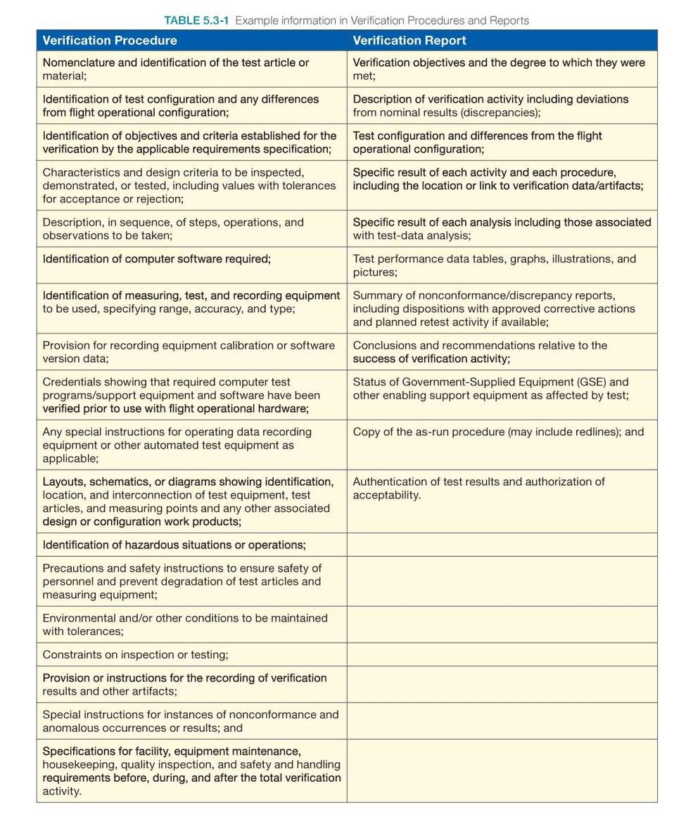
Table 5.3-1 provides an example of the type of information that may be included in a verification procedure and a verification report.
Outcomes of verification preparation include the following:
- The verification plan, approved procedures, and an appropriate baseline set of specified requirements and supporting configuration documentation is available and on hand;
- Articles/models to be verified and verification-enabling products are on hand, assembled, and integrated with the verification environment according to verification plans and schedules;
- The resources (funding, facilities, and people including appropriately skilled operators) needed to conduct the verification are available according to the verification plans and schedules; and
- The verification environment is evaluated for adequacy, completeness, readiness, and integration.
5.3.1.2.2 Perform Product Verification
The actual act of verifying the end product is performed as spelled out in the plans and procedures, and conformance is established with each specified product requirement. The verification lead should ensure that the procedures were followed and performed as planned, the verification-enabling products and instrumentation were calibrated correctly, and the data were collected and recorded for required verification measures.
A verification program may include verifications at several layers in the product hierarchy. Some verifications need to be performed at the lowest component level if the ability to verify a requirement at a higher assembly is not possible. Likewise, there may be verifications at assemblies, sub-systems and system levels. If practicable, a final set of testing with as much of the end-to-end configuration as possible is important.
The purpose of end-to-end testing is to demonstrate interface compatibility and desired total functionality among different elements of a mission system, between systems (the system of interest and external enabling systems), and within a system as a whole. It can involve real or representative input and operational scenarios. End-to-end tests performed on the integrated ground and flight assets include all elements of the flight article (payload or vehicle), its control, stimulation, communications, and data processing to demonstrate that the entire integrated mission system is operating in a manner to fulfill all mission requirements and objectives. End-to-end tests may be performed as part of investigative engineering tests, verification testing, or validation testing. These are some of the most important tests for the systems engineers to participate in or to lead. They review the overall compatibility of the various systems and demonstrate compliance with system-level requirements and whether the system behaves as expected by the stakeholders.
End-to-end testing includes executing complete threads or operational scenarios across multiple configuration items, ensuring that all mission requirements are verified and validated. Operational scenarios are used extensively to ensure that the mission system (or collections of systems) will successfully execute mission requirements. Operational scenarios are a step-by-step description of how the system should operate and interact with its users and its external interfaces (e.g., other systems). Scenarios should be described in a manner that allows engineers to walk through them and gain an understanding of how all the various parts of the system should function and interact as well as verify that the system will satisfy the user’s goals and expectations (MOEs). Operational scenarios should be described for all operational modes, mission phases (e.g., installation, startup, typical examples of normal and contingency operations, shutdown, and maintenance), and critical sequences of activities for all classes of users identified. Each scenario should include events, actions, stimuli, information, and interactions as appropriate to provide a comprehensive understanding of the operational aspects of the system.
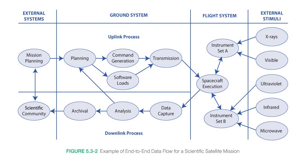
Figure 5.3-2 presents an example of an end-to-end data flow for a scientific satellite mission. Each arrow in the diagram represents one or more data or control flows between two hardware, software, subsystem, or system configuration items. End-to-end testing verifies that the data flows throughout the multisystem environment are correct, that the system provides the required functionality, and that the outputs at the eventual end points correspond to expected results. Since the test environment is as close an approximation as possible to the operational environment, system performance requirements testing is also included. This figure is not intended to show the full extent of end-to-end testing. Each system shown would need to be broken down into a further level of granularity for completeness.
End-to-end testing is an integral part of the verification and validation of the total (mission) system. It is a set of activities that can be employed during selected hardware, software, and system phases throughout the life cycle using developmental forms and external simulators. However, final end-to-end testing should be done on the flight articles in the flight configuration if possible and prior to deployment and launch. In comparison with configuration item testing, end-to-end testing addresses each configuration item (end product) only down to the level designated by the verification plan (generally, the segment r element) and focuses on external interfaces, which can be either hardware, software, or human-based. Internal interfaces (e.g., software subroutine calls, analog-to-digital conversion) of a designated configuration item are not within the scope of end-to-end testing.
When a “discrepancy” is observed (i.e., any variance, lack of agreement, or contradiction with the required or expected outcome, configuration, or result), verification activities should stop and a discrepancy report should be generated. The activities and events leading up to the discrepancy should be analyzed to determine if a nonconforming product exists or there is an issue with the verification procedure or conduct. The Decision Analysis Process should be used to make decisions with respect to needed changes in the verification plans, environment, and/or procedures.
Outcomes of performing product verification include the following:
- A verified product is established with supporting confirmation that the product (in the appropriate form for the life cycle phase) complies with its specified requirements, and if it does not, a nonconformance report delineating the variance is available.
- A determination is made as to whether the appropriate results were collected and evaluated to show completion of verification objectives throughout their performance envelope.
- A determination is made that the verification product was appropriately integrated with the enabling products and verification environment.
5.3.1.2.3 Analyze Product Verification Results and Report
As the verification activities are completed, the results are collected and analyzed. The data are analyzed for quality, integrity, correctness, consistency, and validity. Any verification discrepancies (anomalies, variations, and out-of-compliance conditions) are identified and reviewed to determine if there is a nonconforming product not resulting from poor verification conduct, procedure, or conditions. If possible, this analysis is performed while the test/analysis configuration is still intact. This allows a quick turnaround in case the data indicates that a correction to the test or analysis run needs to be performed again.
Discrepancies and nonconforming products should be recorded and reported for follow-up action and closure. Verification results should be recorded in a requirements compliance or verification matrix or other method developed during the Technical Requirements Definition Process to trace compliance for each product requirement. Waivers needed as a result of verification to request relief from or modify a requirement are identified.
System design and product realization process activities may be required to resolve product nonconformance. If the mitigation of the nonconformance results in a change to the product, the verification may need to be planned and performed again.
Note: Nonconformance and discrepancy reports may be directly linked with the Technical Risk Management Process. Depending on the nature of the nonconformance, approval through such bodies as a Material Review Board or Configuration Control Board (which typically includes risk management participation) may be required.
Outcomes of analyzing the verification results include the following:
- Product nonconformance (not compliant with product requirement) is identified.
- Appropriate replanning, redefinition of requirements, redesign, implementation/integration, modification, and reverification have been accomplished for resolution of the nonconforming product.
- Appropriate facility modifications, procedure corrections, enabling product modification, and reverification have been performed for non-product-related discrepancies.
- Waivers for nonconforming products are accepted.
- Discrepancy and nonconformance reports including corrective actions have been generated as needed.
- The verification report is completed.
Re-engineering
Based on analysis of verification results, it could be necessary to re-realize the end product used for verification or to re-engineer the end products assembled and integrated into the product being verified, based on where and what type of nonconformance was found.
Re-engineering could require the reapplication of the system design processes (Stakeholder Expectations Definition Process, Technical Requirements Definition Process, Logical Decomposition Process, and Design Solution Definition Process).
5.3.1.2.4 Capture Product Verification Work Products
Verification work products (inputs to the Technical Data Management Process) take many forms and involve many sources of information. The capture and recording of verification results and related data is a very important, but often underemphasized, step in the Product Verification Process.
Verification results, peer review reports, anomalies, and any corrective action(s) taken should be captured, as should all relevant results from the application of the Product Verification Process (related decisions, rationale for the decisions made, assumptions, and lessons learned).
Outcomes of capturing verification work products include the following:
- Verification of work products is recorded, e.g., method of verification, procedures, environments, outcomes, decisions, assumptions, corrective actions, and lessons learned.
- Variations, anomalies, and out-of-compliance conditions have been identified and documented, including the actions taken to resolve them.
- Proof that the realized end product did or did not satisfy the specified requirements is documented.
- The verification report is developed, including:
- recorded test/verification results/data;
- version of the set of specified requirements used;
- version of the product verified;
- version or standard for tools, data, and equipment used;
- results of each verification including pass or fail declarations; and
- discrepancies.
5.3.1.3 Outputs
Key outputs from the process are:
- Verified product ready for validation: After the product is verified, it will next pass through the Product Validation Process.
- Product verification results: Results from executed procedures are passed to technical assessment.
- Product verification report(s): A report shows the results of the verification activities. It includes the requirement that was to be verified and its bidirectional traceability, the verification method used, and reference to any special equipment, conditions, or procedures used. It also includes the results of the verification, any anomalies, variations or out-of-compliance results noted and associated corrective actions taken.
- Product verification work products: These include discrepancy and nonconformance reports with identified correction actions; updates to requirements compliance documentation; changes needed to the procedures, equipment or environment; configuration drawings; calibrations; operator certifications; and other records.
Criteria for completing verification of the product include: (1) documented objective evidence of compliance with requirements or waiver and (2) closure of all discrepancy and nonconformance reports.
5.3.2 Product Verification Guidance
Refer to Section 5.3.2 in the NASA Expanded Guidance for Systems Engineering at https://nen.nasa.gov/web/se/doc-repository for additional guidance on:
- the verification approach,
- verification in the life cycle,
- verification procedures,
- verification reports
- end-to-end testing,
- use of modeling and simulations, and
- hardware-in-the-loop testing.
The Product Validation Process is the second of the verification and validation processes conducted on an implemented or integrated end product. While verification proves whether “the product was done right,” validation proves whether “the right product was done.” In other words, verification provides objective evidence that every “shall” statement in the requirements document or specification was met, whereas validation is performed for the benefit of the customers and users to ensure that the system functions in the expected manner when placed in the intended environment. This is achieved by examining the products of the system at every level of the product structure and comparing them to the stakeholder expectations for that level. A well-structured validation process can save cost and schedule while meeting the stakeholder expectations.
System validation confirms that the integrated realized end products conform to stakeholder expectations as captured in the MOEs, MOPs, and ConOps. Validation also ensures that any anomalies discovered are appropriately resolved prior to product delivery. This section discusses the process activities, methods of validation, inputs and outputs, and potential deficiencies.
See Section 2.4 for a discussion about the distinctions between Product Verification and Product Validation.
5.4.1 Process Description
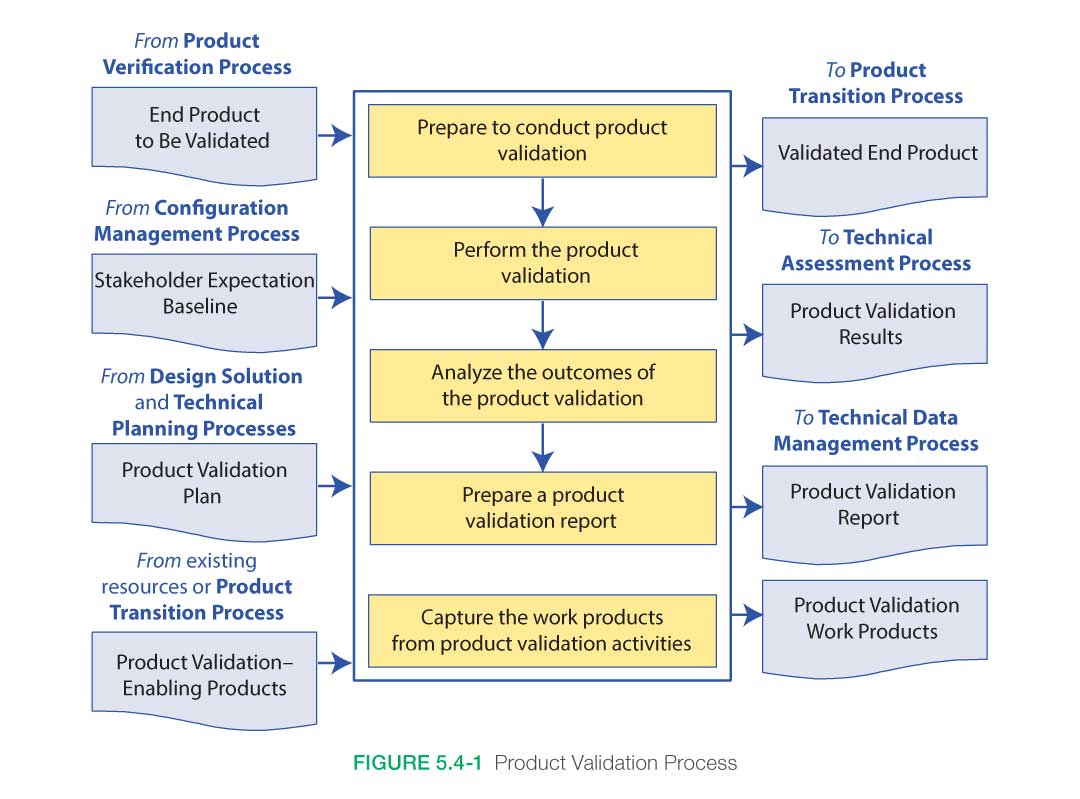
Figure 5.4-1, taken from NPR 7123.1, provides a typical flow diagram for the Product Validation Process and identifies typical inputs, outputs, and activities to consider in addressing product validation.
5.4.1.1 Inputs
Key inputs to the process are:
- End product to be validated: This is the end product that is to be validated and which has successfully passed through the verification process.
- Validation plan: This plan would have been developed under the Technical Planning Process and baselined prior to entering this process. This plan may be a separate document or a section within the Verification and Validation Plan.
- Baselined stakeholder expectations: These would have been developed for the product at this level during the Stakeholder Expectations Definition Process. It includes the needs, goals, and objectives as well as the baselined and updated concept of operations and MOEs.
- Any enabling products: These are any special equipment, facilities, test fixtures, applications, or other items needed to perform the Product Validation Process.
5.4.1.2 Process Activities
The Product Validation Process demonstrates that the end product satisfies its stakeholder (customer and other interested party) expectations (MOEs) within the intended operational environments, with validation performed by anticipated operators and/or users whenever possible. The method of validation is a function of the life cycle phase and the position of the end product within the system structure.
There are five major steps in the validation process: (1) preparing to conduct validation, (2) conduct planned validation (perform validation), (3) analyze validation results, (4) prepare a validation report, and (5) capture the validation work products.
The objectives of the Product Validation Process are:
- To confirm that the end product fulfills its intended use when operated in its intended environment:
- Validation is performed for each implemented or integrated and verified end product from the lowest end product in a system structure branch up to the top level end product (the system).
- Evidence is generated as necessary to confirm that products at each layer of the system structure meet the capability and other operational expectations of the customer/user/operator and other interested parties for that product.
- To ensure the human has been properly integrated into the system:
- The user interface meets human engineering criteria.
- Operators and maintainers have the required skills and abilities.
- Instructions are provided and training programs are in place.
- The working environment supports crew health and safety.
- To ensure that any problems discovered are appropriately resolved prior to delivery of the end product (if validation is done by the supplier of the product) or prior to integration with other products into a higher level assembled product (if validation is done by the receiver of the product).
Methods of Validation
Analysis: The use of mathematical modeling and analytical techniques to predict the suitability of a design to stakeholder expectations based on calculated data or data derived from lower system structure end product verifications. Analysis is generally used when a prototype; engineering model; or fabricated, assembled, and integrated product is not available. Analysis includes the use of modeling and simulation as analytical tools. A model is a mathematical representation of reality. A simulation is the manipulation of a model.
Demonstration: Showing that the use of an end product achieves the stakeholder expectations as defined in the NGOs and the ConOps. It is generally a basic confirmation of behavioral capability, differentiated from testing by the lack of detailed data gathering. Demonstrations can involve the use of physical models or mock-ups; for example, an expectation that controls are readable by the pilot in low light conditions could be validated by having a pilot perform flight-related tasks in a cockpit mock-up or simulator under those conditions.
Inspection: The visual examination of a realized end product. Inspection is generally used to validate the presence of a physical design features or specific manufacturer identification. For example, if there is an expectation that the safety arming pin has a red flag with the words “Remove Before Flight” stenciled on the flag in black letters, a visual inspection of the arming pin flag can be used to determine if this expectation has been met.
Test: The use of an end product to obtain detailed data needed to determine a behavior, or provide sufficient information to determine a behavior through further analysis. Testing can be conducted on final end products, breadboards, brassboards, or prototypes. Testing produces information at discrete points for each specified expectation under controlled conditions and is the most resource-intensive validation technique.
5.4.1.2.1 Product Validation Preparation
To prepare for performing product validation, the appropriate set of expectations, including MOEs and MOPs, against which the validation is to be made should be obtained. In addition to the V&V Plan, other documentation such as the ConOps and HSI Plan may be useful. The product to be validated (output from implementation, or integration and verification), as well as the appropriate enabling products and support resources (requirements identified and acquisition initiated by design solution activities) with which validation will be conducted should be collected. Enabling products includes those representing external interfacing products and special test equipment. Support resources include personnel necessary to support validation and operators. Procedures, capturing detailed step-by-step activities and based on the validation type and methods are finalized and approved. Development of procedures typically begins during the design phase of the project life cycle and matures as the design is matured. The validation environment is considered as part of procedure development. Operational scenarios are assessed to explore all possible validation activities to be performed. The final element is preparation of the validation environment; e.g., facilities, equipment, software, and climatic conditions.
When operator or other user interaction is involved, it is important to ensure that humans are properly represented in the validation activities. This includes physical size, skills, knowledge, training, clothing, special gear, and tools. When possible, actual end users/operators should be used and other stakeholders should participate or observe activities as appropriate and practical.
Outcomes of validation preparation include the following:
- The validation plan, approved procedures, supporting configuration documentation, and an appropriate baseline set of stakeholder expectations are available and on hand;
- Enabling products are integrated within the validation environment according to plans and schedules;
- Users/operators and other resources are available according to validation plans and schedules; and
- The validation environment is evaluated for adequacy, completeness, readiness, and integration.
5.4.1.2.2 Perform Product Validation
The act of validating the end product is performed as spelled out in the validation plans and procedures, and the conformance established to each specified stakeholder expectation (MOEs and ConOps) shows that the validation objectives were met. Validation differs from qualification testing. Validation testing is focused on the expected environments and operations of the system where as qualification testing includes the worst case loads and environmental requirements within which the system is expected to perform or survive. The verification lead should ensure that the procedures were followed and performed as planned, the validation-enabling products and instrumentation were calibrated correctly, and the data were collected and recorded for required validation measures.
When a discrepancy is observed, the validation should be stopped and a discrepancy report generated. The activities and events leading up to the discrepancy should be analyzed to determine if a nonconforming product exists or there is an issue with the verification procedure, conduct, or conditions. If there are no product issues, the validation is replanned as necessary, the environment preparation anomalies are corrected, and the validation is conducted again with improved or correct procedures and resources. The Decision Analysis Process should be used to make decisions with respect to needed changes to the validation plans, environment, and/or conduct.
Outcomes of performing validation include the following:
- A validated product is established with supporting confirmation that the appropriate results were collected and evaluated to show completion of validation objectives.
- A determination is made as to whether the fabricated/manufactured or assembled and integrated products (including software or firmware builds and human element allocations) comply with their respective stakeholder expectations.
- A determination is made that the validated product was appropriately integrated with the validation environment and the selected stakeholder expectations set was properly validated.
- A determination is made that the product being validated functions together with interfacing products throughout their operational envelopes.
5.4.1.2.3 Analyze Product Validation Results
Once the validation activities have been completed, the results are collected and the data are analyzed to confirm that the end product provided will supply the customer’s needed capabilities within the intended environments of use, validation procedures were followed, and enabling products and supporting resources functioned correctly. The data are also analyzed for quality, integrity, correctness, consistency, and validity, and any unsuitable products or product attributes are identified and reported.
It is important to compare the actual validation results to the expected results. If discrepancies are found, it needs to be determined if they are a result of the test configuration or analysis assumptions or whether they are a true characteristic or behavior of the end product. If it is found to be a result of the test configuration, the configuration should be corrected and the validation repeated. If it is found to be a result of the end product being validated, discussions with the customer should be held and any required system design and product realization process activities should be conducted to resolve deficiencies. The deficiencies along with recommended corrective actions and resolution results should be recorded, and validation should be repeated, as required.
Outcomes of analyzing validation results include the following:
- Product anomalies, variations, deficiencies, nonconformance and/or issues are identified.
- Assurances that appropriate replanning, redefinition of requirements, design, and revalidation have been accomplished for resolution of anomalies, variations, deficiencies or out-of-compliance conditions (for problems not caused by poor validation conduct).
- Discrepancy and corrective action reports are generated as needed.
- The validation report is completed.
Re-engineering
Based on the results of the Product Validation Process, it could become necessary to re-engineer a deficient end product. Care should be taken that correcting a deficiency or set of deficiencies does not generate a new issue with a part or performance that had previously operated satisfactorily. Regression testing, a formal process of rerunning previously used acceptance tests (primarily used for software), is one method to ensure a change does not affect function or performance that was previously accepted.
Validation Deficiencies
Validation outcomes can be unsatisfactory for several reasons. One reason is poor conduct of the validation (e.g., enabling products and supporting resources missing or not functioning correctly, untrained operators, procedures not followed, equipment not calibrated, or improper validation environmental conditions) and failure to control other variables not involved in validating a set of stakeholder expectations. A second reason could be a shortfall in the verification process of the end product. This could create the need for:
- Re-engineering end products lower in the system structure that make up the end product that was found to be deficient (i.e., that failed to satisfy validation requirements); and/or
- Re-performing any needed verification and validation processes.
Other reasons for validation deficiencies (particularly when M&S are involved) may be incorrect and/or inappropriate initial or boundary conditions; poor formulation of the modeled equations or behaviors; the impact of approximations within the modeled equations or behaviors; failure to provide the required geometric and physics fidelities needed for credible simulations for the intended purpose; and/or poor spatial, temporal, and perhaps, statistical resolution of physical phenomena used in M&S.
Note: Care should be exercised to ensure that the corrective actions identified to remove validation deficiencies do not conflict with the baselined stakeholder expectations without first coordinating such changes with the appropriate stakeholders.
Of course, the ultimate reason for performing validation is to determine if the design itself is the right design for meeting stakeholder expectations. After any and all validation test deficiencies are ruled out, the true value of validation is to identify design changes needed to ensure the program/product’s mission. Validation should be performed as early and as iteratively as possible in the SE process since the earlier re-engineering needs are discovered, the less expensive they are to resolve.
Pass Verification but Fail Validation?
Sometimes systems successfully complete verification but then are unsuccessful in some critical phase of the validation process, delaying development and causing extensive rework and possible compromises with the stakeholder. Developing a solid ConOps in early phases of the project (and refining it through the requirements development and design phases) is critical to preventing unsuccessful validation. Similarly, developing clear expectations for user community involvement in the HSI Plan is critical to successful validation. Frequent and iterative communications with stakeholders helps to identify operational scenarios and key needs that should be understood when designing and implementing the end product. Should the product fail validation, redesign may be a necessary reality. Review of the understood requirements set, the existing design, operational scenarios, user population numbers and skills, training, and support material may be necessary, as well as negotiations and compromises with the customer, other stakeholders, and/or end users to determine what, if anything, can be done to correct or resolve the situation. This can add time and cost to the overall project or, in some cases, cause the project to fail or be canceled. However, recall from Figure 2.5-1 that the earlier design issues are discovered, the less costly the corrective action.
5.4.1.2.4 Prepare Report and Capture Product Validation Work Products
Validation work products (inputs to the Technical Data Management Process) take many forms and involve many sources of information. The capture and recording of validation-related data is a very important, but often underemphasized, step in the Product Validation Process.
Validation results, deficiencies identified, and corrective actions taken should be captured, as should all relevant results from the application of the Product Validation Process (related decisions, rationale for decisions made, assumptions, and lessons learned).
Outcomes of capturing validation work products include the following:
- Work products and related information generated while doing Product Validation Process activities and tasks are recorded; i.e., method of validation conducted, the form of the end product used for validation, validation procedures used, validation environments, outcomes, decisions, assumptions, corrective actions, lessons learned, etc. (often captured in a matrix or other tool—see Appendix E).
- Deficiencies (e.g., variations and anomalies and out-of-compliance conditions) are identified and documented, including the actions taken to resolve.
- Proof is provided that the end product is in conformance with the stakeholder expectation set used in the validation.
- Validation report including:
- Recorded validation results/data;
- Version of the set of stakeholder expectations used;
- Version and form of the end product validated;
- Version or standard for tools and equipment used, together with applicable calibration data;
- Outcome of each validation including pass or fail declarations; and
- Discrepancy between expected and actual results.
Note: For systems where only a single deliverable item is developed, the Product Validation Process normally completes acceptance testing of the system. However, for systems with several production units, it is important to understand that continuing verification and validation is not an appropriate approach to use for the items following the first deliverable. Instead, acceptance testing is the preferred means to ensure that subsequent deliverables meet stakeholder expectations.
5.4.1.3 Outputs
Key outputs of validation are:
- Validated end product: This is the end product that has successfully passed validation and is ready to be transitioned to the next product layer or to the customer.
- Product validation results: These are the raw results of performing the validations.
- Product validation report: This report provides the evidence of product conformance with the stakeholder expectations that were identified as being validated for the product at this layer. It includes any nonconformance, anomalies, or other corrective actions that were taken.
- Work products: These include procedures, required personnel training, certifications, configuration drawings, and other records generated during the validation activities.
Success criteria for this process include: (1) objective evidence of performance and the results of each system-of-interest validation activity are documented, and (2) the validation process should not be considered or designated as complete until all issues and actions are resolved.
5.4.2 Product Validation Guidance
Refer to Section 5.4.2 in the NASA Expanded Guidance for Systems Engineering at https://nen.nasa.gov/web/se/doc-repository for additional guidance on:
- use of modeling and simulation,
- software validation, and
- taking credit for validation.
The Product Transition Process is used to transition a verified and validated end product that has been generated by product implementation or product integration to the customer at the next level in the system structure for integration into an end product or, for the top-level end product, transitioned to the intended end user. The form of the product transitioned will be a function of the product life cycle phase success criteria and the location within the system structure of the WBS model in which the end product exists. The systems engineer involvement in this process includes ensuring the product being transitioned has been properly tested and verified/validated prior to being shipped to the next level stakeholder/customer.
Product transition occurs during all phases of the life cycle. During the early phases, the technical team’s products are documents, models, studies, and reports. As the project moves through the life cycle, these paper or soft products are transformed through implementation and integration processes into hardware and software solutions to meet the stakeholder expectations. They are repeated with different degrees of rigor throughout the life cycle. The Product Transition Process includes product transitions from one level of the system architecture upward. The Product Transition Process is the last of the product realization processes, and it is a bridge from one level of the system to the next higher level.
The Product Transition Process is the key to bridge from one activity, subsystem, or element to the overall engineered system. As the system development nears completion, the Product Transition Process is again applied for the end product, but with much more rigor since now the transition objective is delivery of the system-level end product to the actual end user. Depending on the kind or category of system developed, this may involve a Center or the Agency and impact thousands of individuals storing, handling, and transporting multiple end products; preparing user sites; training operators and maintenance personnel; and installing and sustaining, as applicable. Examples are transitioning the external tank, solid rocket boosters, and orbiter to Kennedy Space Center (KSC) for integration and flight. Another example is the transition of a software subsystem for integration into a combined hardware/software system.
5.5.1 Process Description
Figure 5.5-1 provides a typical flow diagram for the Product Transition Process and identifies typical inputs, outputs, and activities to consider in addressing product transition.
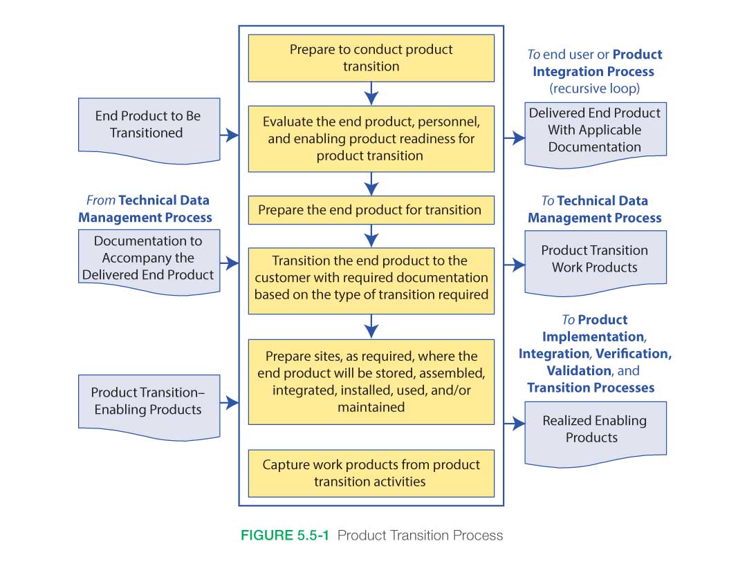
5.5.1.1 Inputs
Inputs to the Product Transition Process depend primarily on the transition requirements, the product that is being transitioned, the form of the product transition that is taking place, and the location to which the product is transitioning. Typical inputs are shown in Figure 5.5-1 and described below.
- The end product or products to be transitioned (from the Product Validation Process): The product to be transitioned can take several forms. It can be a subsystem component, system assembly, or top-level end product. It can be hardware, analytical models, or software. It can be newly built, purchased, or reused. A product can transition from a lower system product to a higher one by being integrated with other transitioned products. This process may be repeated until the final end product is achieved. Each succeeding transition requires unique input considerations when preparing the validated product for transition to the next level.
Early phase products can take the form of information or data generated from basic or applied research using analytical or physical models and are often in paper or electronic form. In fact, the end product for many NASA research projects or science activities is a report, paper, model, or even an oral presentation. In a sense, the dissemination of information gathered through NASA research and development is an important form of product transition.
- Documentation including manuals, procedures, and processes that accompany the end product (from the Technical Data Management Process): The documentation required for the Product Transition Process depends on the specific end product; its current location within the system structure; and the requirements identified in various agreements, plans, or requirements documents. Typically, a product has a unique identification (i.e., serial or version number) and may have a pedigree (documentation) that specifies its heritage and current state. Pertinent information may be controlled using a configuration control process or work order system as well as design drawings and test reports. Documentation often includes proof of verification and validation conformance. A COTS product would typically contain a manufacturer’s specification or fact sheet. Documentation may include operations manuals, installation instructions, and other information.
The documentation level of detail is dependent upon where the product is within the product hierarchy and the life cycle. Early in the life cycle, this documentation may be conceptual or preliminary in nature. Later in the life cycle, the documentation may be detailed design documents, user manuals, drawings, or other work products. Documentation that is gathered during the input process for the transition phase may require editing, assembling, or repackaging to ensure it is in the required condition for acceptance by the customer.
Special consideration should be given to safety, including clearly identifiable tags and markings that identify the use of hazardous materials, special handling instructions, and storage requirements.
- Product transition-enabling products, including packaging materials; containers; handling equipment; and storage, receiving, and shipping facilities (from existing resources or the Product Transition Process for enabling product realization): Product transition-enabling products may be required to facilitate the implementation, integration, evaluation, transition, training, operations, support, and/or retirement of the transition product at its next higher level or for the transition of the final end product. Some or all of the enabling products may be defined in transition-related agreements, system requirements documents, or project plans. In some cases, product transition-enabling products are developed during the realization of the product itself or may be required to be developed during the transition stage.
As a product is developed, special containers, holders, or other devices may also be developed to aid in the storing and transporting of the product through development and realization. These may be temporary accommodations that do not satisfy all the transition requirements, but allow the product to be initiated into the transition process. In such cases, the temporary accommodations will have to be modified or new accommodations will need to be designed and built or procured to meet specific transportation, handling, storage, and shipping requirements.
Sensitive or hazardous products may require special enabling products such as monitoring equipment, security features, inspection devices, safety devices, and personnel training to ensure adequate safety and environmental requirements are achieved and maintained.
5.5.1.2 Process Activities
Transitioning the product can take one of two forms:
- The delivery of lower system end products to higher ones for integration into another end product; or
- The delivery of the final end product to the customer or user that will use it in its operational environment.
In the first case, the end product is one of perhaps several other pieces that will ultimately be integrated together to form the item. In the second case, the end product is for final delivery to the customer. For example, the end product might be one of several circuit cards that will be integrated together to form the final unit that is delivered. Or that unit might also be one of several units that have to be integrated together to form the final product.
The form of the product transitioned is not only a function of the location of that product within the system product hierarchy, but also a function of the life cycle phase. Early life cycle phase products may be in the form of paper, electronic files, physical models, or technology demonstration prototypes. Later phase products may be preproduction prototypes (engineering models), the final study report, or the flight units.
Figure 5.5-1 shows what kind of inputs, outputs, and activities are performed during product transition regardless of where in the product hierarchy or life cycle the product is. These activities include preparing to conduct the transition; making sure the end product, all personnel, and any enabling products are ready for transitioning; preparing the site; and performing the transition including capturing and documenting all work products.
How these activities are performed and what form the documentation takes depends on where the end items are in the product hierarchy and the life cycle phase.
5.5.1.2.1 Prepare to Conduct Transition
The first task is to identify which of the two forms of transition is needed: (1) the delivery of lower system end products to higher ones for integration into another end product; or (2) the delivery of the final end product to the customer or user that will use the end product in its operational environment. The form of the product being transitioned affects transition planning and the kind of packaging, handling, storage, and transportation that is required. The customer and other stakeholder expectations, as well as the specific design solution, may indicate special transition procedures or enabling product needs for packaging, storage, handling, shipping/transporting, site preparation, installation, and/or sustainability. These requirements need to be reviewed during the preparation stage.
Other tasks in preparing to transition a product involve making sure the end product, personnel, and any enabling products are ready for that transition. This includes the availability of the documentation or models that will be sent with the end product, including proof of verification and validation conformance. The appropriateness of detail for that documentation depends upon where the product is within the product hierarchy and the life cycle. Early in the life cycle, this documentation may be preliminary in nature. Later in the life cycle, the documentation may be detailed design documents, user manuals, drawings, or other work products. Procedures necessary for conducting the transition should be reviewed and approved by this time.
Finally, the availability and skills of personnel needed to conduct the transition as well as the availability of any necessary packaging materials/containers, handling equipment, storage facilities, and shipping/transporter services should also be reviewed. Any special training necessary for the personnel to perform their tasks needs to be performed by this time.
5.5.1.2.2 Prepare the Site to Receive the Product
For either of the forms of product transition, the receiving site needs to be prepared to receive the product. Here the end product is stored, assembled, integrated, installed, used, and/or maintained as appropriate for the life cycle phase, position of the end product in the system structure, and customer agreement.
A vast number of key complex activities, many of them outside direct control of the technical team, need to be synchronized to ensure smooth transition to the end user. If transition activities are not carefully controlled, there can be impacts on schedule, cost, and safety of the end product.
A site survey may need to be performed to determine the issues and needs. This should address the adequacy of existing facilities to accept, store, and operate the new end product and identify any logistical-support-enabling products and services required but not planned for. Additionally, any modifications to existing facilities should be planned well in advance of fielding; therefore, the site survey should be made during an early phase in the product life cycle. These may include logistical enabling products and services to provide support for end-product use, operations, maintenance, and disposal. Training for users, operators, maintainers, and other support personnel may need to be conducted. National Environmental Policy Act documentation or approvals may need to be obtained prior to the receipt of the end product.
Prior to shipment or after receipt, the end product may need to be stored in suitable storage conditions to protect and secure the product and prevent damage or the deterioration of it. These conditions should have been identified early in the design life cycle.
5.5.1.2.3 Prepare the Product for Transition
Whether transitioning a product to the next room for integration into the next higher assembly, or for final transportation across the country to the customer, care should be taken to ensure the safe transportation of the product. The requirements for packaging, handling, storage, training, and transportation should have been identified during system design. Preparing the packaging for protection, security, and prevention of deterioration is critical for products placed in storage or when it is necessary to transport or ship between and within organizational facilities or between organizations by land, air, and/or water vehicles. Particular emphasis needs to be on protecting surfaces from physical damage, preventing corrosion, eliminating damage to electronic wiring or cabling, shock or stress damage, heat warping or cold fractures, moisture, and other particulate intrusion that could damage moving parts.
The design requirements should have already addressed the ease of handling or transporting the product such as component staking, addition of transportation hooks, crating, etc. The ease and safety of packing and unpacking the product should also have been addressed. Additional measures may also need to be implemented to show accountability and to securely track the product during transportation. In cases where hazardous materials are involved, special labeling or handling needs, including transportation routes, need to be in place.
5.5.1.2.4 Transition the Product
The end product is then transitioned (i.e., moved, transported, or shipped) with required documentation to the customer based on the type of transition required, e.g., to the next higher level item in the product hierarchy (often called the Product Breakdown Structure [PBS]) for product integration or to the end user. Documentation may include operations manuals, installation instructions, and other information.
The end product is finally installed into the next higher assembly or into the customer/user site using the preapproved installation procedures.
Confirm Ready to Support
After installation, whether into the next higher assembly or into the final customer site, functional and acceptance testing of the end product should be conducted. This ensures no damage from the shipping/handling process has occurred and that the product is ready for support. Any final transitional work products should be captured as well as documentation of product acceptance.
5.5.1.2.5 Capture Product Transition Work Products
Other work products generated during the transition process are captured and archived as appropriate. These may include site plans, special handling procedures, training, certifications, videos, inspections, or other products from these activities.
5.5.1.3 Outputs
- Delivered end product with applicable documentation: This may take one of two forms:
- Delivered end product for integration to next level up in system structure: This includes the appropriate documentation. The form of the end product and applicable documentation are a function of the life cycle phase and the placement within the system structure. (The form of the end product could be hardware, software, model, prototype, first article for test, or single operational article or multiple production articles.) Documentation includes applicable draft installation, operation, user, maintenance, or training manuals; applicable baseline documents (configuration baseline, specifications, and stakeholder expectations); and test results that reflect completion of verification and validation of the end product.
- Delivered operational end product for end users: The appropriate documentation is to accompany the delivered end product as well as the operational end product appropriately packaged. Documentation includes applicable final installation, operation, user, maintenance, or training manuals; applicable baseline documents (configuration baseline, specifications, stakeholder expectations); and test results that reflect completion of verification and validation of the end product. If the end user will perform end product validation, sufficient documentation to support end user validation activities is delivered with the end product.
- Work products from transition activities to technical data management: Work products could include the transition plan, site surveys, measures, training modules, procedures, decisions, lessons learned, corrective actions, etc.
- Realized enabling end products to appropriate life cycle support organization: Some of the enabling products that were developed during the various phases could include fabrication or integration specialized machines; tools; jigs; fabrication processes and manuals; integration processes and manuals; specialized inspection, analysis, demonstration, or test equipment; tools; test stands; specialized packaging materials and containers; handling equipment; storage-site environments; shipping or transportation vehicles or equipment; specialized courseware; instructional site environments; and delivery of the training instruction. For the later life cycle phases, enabling products that are to be delivered may include specialized mission control equipment; data collection equipment; data analysis equipment; operations manuals; specialized maintenance equipment, tools, manuals, and spare parts; specialized recovery equipment; disposal equipment; and readying recovery or disposal site environments.
The process is complete when the following activities have been accomplished:
- For deliveries to the integration path, the end product is delivered to intended usage sites in a condition suitable for integration with other end products or composites of end products. Procedures, decisions, assumptions, anomalies, corrective actions, lessons learned, etc., resulting from transition for integration are recorded.
- For delivery to the end user path, the end products are installed at the appropriate sites; appropriate acceptance and certification activities are completed; training of users, operators, maintainers, and other necessary personnel is completed; and delivery is closed out with appropriate acceptance documentation.
- Any realized enabling end products are also delivered as appropriate including procedures, decisions, assumptions, anomalies, corrective actions, lessons learned, etc., resulting from transition-enabling products.
5.5.2 Product Transition Guidance
Refer to Section 5.5.2 in the NASA Expanded Guidance for Systems Engineering at https://nen.nasa.gov/web/se/doc-repository for additional guidance on:
- additional product transition considerations and
- what’s next after product transition to the end user.