


![Request for Information – Potential [Placeholder for Prize]](https://assets.science.nasa.gov/dynamicimage/assets/science/psd/solar/2023/09/s/solarsystem_0.jpg?w=1024)


This chapter describes the activities in the system design processes listed in Figure 2.1-1. The chapter is separated into sections corresponding to processes 1 to 4 listed in Figure 2.1-1. The tasks within each process are discussed in terms of inputs, activities, and outputs. Additional guidance is provided using examples that are relevant to NASA projects.
The system design processes are interdependent, highly iterative and recursive processes resulting in a validated set of requirements and a design solution that satisfies a set of stakeholder expectations. There are four system design processes: developing stakeholder expectations, technical requirements, logical decompositions, and design solutions.
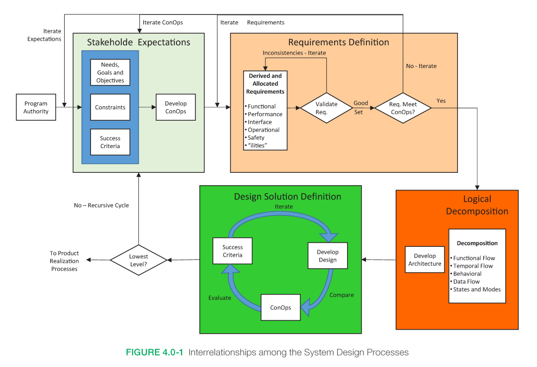
Figure 4.0-1 illustrates the recursive relationship among the four system design processes. These processes start with a study team collecting and clarifying the stakeholder expectations, including the mission objectives, constraints, design drivers, operational objectives, and criteria for defining mission success. This set of stakeholder expectations and high-level requirements is used to drive an iterative design loop where a straw man architecture/design, the concept of operations, and derived requirements are developed. These three products should be consistent with each other and will require iterations and design decisions to achieve this consistency. Once consistency is achieved, analyses allow the project team to validate the proposed design against the stakeholder expectations. A simplified validation asks the questions: Will the system work as expected? Is the system achievable within budget and schedule constraints? Does the system provide the functionality and fulfill the operational needs that drove the project’s funding approval? If the answer to any of these questions is no, then changes to the design or stakeholder expectations will be required, and the process starts again. This process continues until the system—architecture, ConOps, and requirements—meets the stakeholder expectations.
The depth of the design effort should be sufficient to allow analytical verification of the design to the requirements. The design should be feasible and credible when judged by a knowledgeable independent review team and should have sufficient depth to support cost modeling and operational assessment.
Once the system meets the stakeholder expectations, the study team baselines the products and prepares for the next phase. Often, intermediate levels of decomposition are validated as part of the process. In the next level of decomposition, the baselined derived (and allocated) requirements become the set of high-level requirements for the decomposed elements and the process begins again. These system design processes are primarily applied in Pre-Phase A and continue through Phase C.
The system design processes during Pre-Phase A focus on producing a feasible design that will lead to Formulation approval. During Phase A, alternative designs and additional analytical maturity are pursued to optimize the design architecture. Phase B results in a preliminary design that satisfies the approval criteria. During Phase C, detailed, build-to designs are completed.
This is a simplified description intended to demonstrate the recursive relationship among the system design processes. These processes should be used as guidance and tailored for each study team depending on the size of the project and the hierarchical level of the study team. The next sections describe each of the four system design processes and their associated products for a given NASA mission.
System Design Keys
- Successfully understanding and defining the mission objectives and the concept of operations are keys to capturing the stakeholder expectations, which will translate into quality requirements and operational efficiencies over the life cycle of the project.
- Complete and thorough requirements traceability is a critical factor in successful validation of requirements.
- Clear and unambiguous requirements will help avoid misunderstanding when developing the overall system and when making major or minor changes.
- Document all decisions made during the development of the original design concept in the technical data package. This will make the original design philosophy and negotiation results available to assess future proposed changes and modifications against.
- The validation of a design solution is a continuing recursive and iterative process during which the design solution is evaluated against stakeholder expectations.
4.1 Stakeholder Expectations Definition
The Stakeholder Expectations Definition Process is the initial process within the SE engine that establishes the foundation from which the system is designed and the product is realized. The main purpose of this process is to identify who the stakeholders are and how they intend to use the product. This is usually accomplished through use-case scenarios (sometimes referred to as Design Reference Missions [DRMs]) and the ConOps.
4.1.1 Process Description
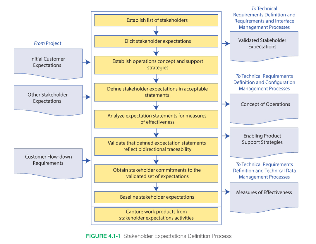
Figure 4.1-1 provides a typical flow diagram for the Stakeholder Expectations Definition Process and identifies typical inputs, outputs, and activities to consider in defining stakeholder expectations.
4.1.1.1 Inputs
Typical inputs needed for the Stakeholder Expectations Definition Process include the following:
- Initial Customer Expectations: These are the needs, goals, objectives, desires, capabilities, and other constraints that are received from the customer for the product within the product layer. For the top-tier products (final end item), these are the expectations of the originating customer who requested the product. For an end product within the product layer, these are the expectations of the recipient of the end item when transitioned.
- Other Stakeholder Expectations: These are the expectations of key stakeholders other than the customer. For example, such stakeholders may be the test team that will be receiving the transitioned product (end product and enabling products) or the trainers that will be instructing the operators or managers that are accountable for the product at this layer.
- Customer Flow-down Requirements: These are any requirements that are being flowed down or allocated from a higher level (i.e., parent requirements). They are helpful in establishing the expectations of the customer at this layer.
4.1.1.2 Process Activities
4.1.1.2.1 Identify Stakeholders
A “stakeholder” is a group or individual that is affected by or has a stake in the product or project. The key players for a project/product are called the key stakeholders. One key stakeholder is always the “customer.” The customer may vary depending on where the systems engineer is working in the PBS. For example, at the topmost level, the customer may be the person or organization that is purchasing the product. For a systems engineer working three or four levels down in the PBS, the customer may be the leader of the team that takes the element and integrates it into a larger assembly. Regardless of where the systems engineer is working within the PBS, it is important to understand what is expected by the customer.
Other interested parties are those who affect the project by providing broad, overarching constraints within which the customers’ needs should be achieved. These parties may be affected by the resulting product, the manner in which the product is used, or have a responsibility for providing life cycle support services. Examples include Congress, advisory planning teams, program managers, maintainers, and mission partners. It is important that the list of stakeholders be identified early in the process, as well as the primary stakeholders who will have the most significant influence over the project.
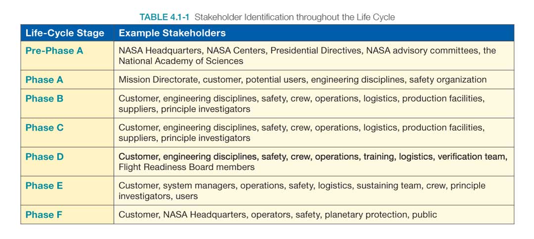
The customer and users of the system are usually easy to identify. The other key stakeholders may be more difficult to identify and they may change depending on the type of the project and the phase the project is in. Table 4.1-1 provides some examples of stakeholders in the life cycle phase that should be considered.
4.1.1.2.2 Understand Stakeholder Expectations
Thoroughly understanding the customer and other key stakeholders’ expectations for the project/product is one of the most important steps in the systems engineering process. It provides the foundation upon which all other systems engineering work depends. It helps ensure that all parties are on the same page and that the product being provided will satisfy the customer. When the customer, other stakeholders, and the systems engineer mutually agree on the functions, characteristics, behaviors, appearance, and performance the product will exhibit, it sets more realistic expectations on the customer’s part and helps prevent significant requirements creep later in the life cycle.
Through interviews/discussions, surveys, marketing groups, e-mails, a Statement of Work (SOW), an initial set of customer requirements, or some other means, stakeholders specify what is desired as an end state or as an item to be produced and put bounds on the achievement of the goals. These bounds may encompass expenditures (resources), time to deliver, life cycle support expectations, performance objectives, operational constraints, training goals, or other less obvious quantities such as organizational needs or geopolitical goals. This information is reviewed, summarized, and documented so that all parties can come to an agreement on the expectations.
Figure 4.1-2 shows the type of information needed when defining stakeholder expectations and depicts how the information evolves into a set of high-level requirements. The yellow lines depict validation paths. Examples of the types of information that would be defined during each step are also provided.
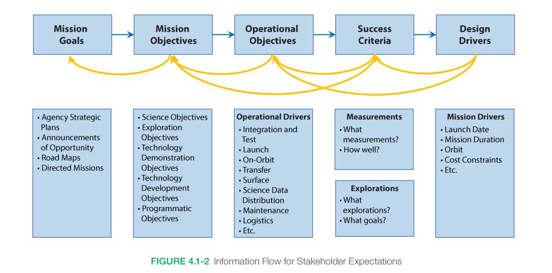
Defining stakeholder expectations begins with the mission authority and strategic objectives that the mission is meant to achieve. Mission authority changes depending on the category of the mission. For example, science missions are usually driven by NASA Science Mission Directorate strategic plans, whereas the exploration missions may be driven by a Presidential directive. Understanding the objectives of the mission helps ensure that the project team is working toward a common vision. These goals and objectives form the basis for developing the mission, so they need to be clearly defined and articulated.
The project team should also identify the constraints that may apply. A “constraint” is a condition that is to be met. Sometimes a constraint is dictated by external factors such as orbital mechanics, an existing system that must be utilized (external interface), a regulatory restriction, or the state of technology; sometimes constraints are the result of the overall budget environment. Concepts of operation and constraints also need to be included in defining the stakeholder expectations. These identify how the system should be operated to achieve the mission objectives.
NOTE: It is extremely important to involve stakeholders in all phases of a project. Such involvement should be built in as a self-correcting feedback loop that will significantly enhance the chances of mission success. Involving stakeholders in a project builds confidence in the end product and serves as a validation and acceptance with the target audience.
In identifying the full set of expectations, the systems engineer will need to interact with various communities, such as those working in the areas of orbital debris, space asset protection, human systems integration, quality assurance, and reliability. Ensuring that a complete set of expectations is captured will help prevent “surprise” features from arising later in the life cycle. For example, space asset protection may require additional encryption for the forward link commands, additional shielding or filtering for RF systems, use of a different frequency, or other design changes that might be costly to add to a system that has already been developed.
4.1.1.2.3 Identify Needs, Goals, and Objectives
In order to define the goals and objectives, it is necessary to elicit the needs, wants, desires, capabilities, external interfaces, assumptions, and constraints from the stakeholders. Arriving at an agreed-to set of goals and objectives can be a long and arduous task. Proactive iteration with the stakeholders throughout the systems engineering process is the way that all parties can come to a true understanding of what should be done and what it takes to do the job. It is important to know who the primary stakeholders are and who has the decision authority to help resolve conflicts.
Needs, Goals, and Objectives (NGOs) provide a mechanism to ensure that everyone (implementer, customer, and other stakeholders) is in agreement at the beginning of a project in terms of defining the problem that needs to be solved and its scope. NGOs are not contractual requirements or designs.
Needs are defined in the answer to the question “What problem are we trying to solve?” Goals address what must be done to meet the needs; i.e., what the customer wants the system to do. Objectives expand on the goals and provide a means to document specific expectations. (Rationale should be provided where needed to explain why the need, goal, or objective exists, any assumptions made, and any other information useful in understanding or managing the NGO.)
Well-written NGOs provide clear traceability from the needs, then to the goals, and then to objectives. For example, if a given goal does not support a need, or an objective does not support a goal, it should not be part of the integrated set of NGOs. This traceability helps ensure that the team is actually providing what is needed.
The following definitions (source: Applied Space Systems Engineering edited by Larson, Kirkpatrick, Sellers, Thomas, and Verma) are provided to help the reader interpret the NGOs contained in this product.
- Need: A single statement that drives everything else. It should relate to the problem that the system is supposed to solve but not be the solution. The need statement is singular. Trying to satisfy more than one need requires a trade between the two, which could easily result in failing to meet at least one, and possibly several, stakeholder expectations.
- Goals: An elaboration of the need, which constitutes a specific set of expectations for the system. Goals address the critical issues identified during the problem assessment. Goals need not be in a quantitative or measurable form, but they should allow us to assess whether the system has achieved them.
- Objectives: Specific target levels of outputs the system must achieve. Each objective should relate to a particular goal. Generally, objectives should meet four criteria. (1) They should be specific enough to provide clear direction, so developers, customers, and testers will understand them. They should aim at results and reflect what the system needs to do but not outline how to implement the solution. (2) They should be measurable, quantifiable, and verifiable. The project needs to monitor the system’s success in achieving each objective. (3) They should be aggressive but attainable, challenging but reachable, and targets need to be realistic. Objectives “To Be Determined” (TBD) may be included until trade studies occur, operations concepts solidify, or technology matures. Objectives need to be feasible before requirements are written and systems designed. (4) They should be results-oriented focusing on desired outputs and outcomes, not on the methods used to achieve the target (what, not how). It is important to always remember that objectives are not requirements. Objectives are identified during pre-Phase A development and help with the eventual formulation of a requirements set, but it is the requirements themselves that are contractually binding and will be verified against the “as-built” system design.
These stakeholder expectations are captured and are considered as initial until they can be further refined through development of the concept of operations and final agreement by the stakeholders.
4.1.1.2.4 Establish Concept of Operations and Support Strategies
After the initial stakeholder expectations have been established, the development of a Concept of Operations (ConOps) will further ensure that the technical team fully understands the expectations and how they may be satisfied by the product, and that understanding has been agreed to by the stakeholders. This may lead to further refinement of the initial set of stakeholder expectations if gaps or ambiguous statements are discovered. These scenarios and concepts of how the system will behave provide an implementation-free understanding of the stakeholders’ expectations by defining what is expected without addressing how (the design) to satisfy the need. It captures required behavioral characteristics and the manner in which people will interact with the system. Support strategies include provisions for fabrication, test, deployment, operations, sustainment, and disposal.
The ConOps is an important component in capturing stakeholder expectations and is used in defining requirements and the architecture of a project. It stimulates the development of the requirements and architecture related to the user elements of the system. It serves as the basis for subsequent definition documents such as the operations plan, launch and early orbit plan, and operations handbook, and it provides the foundation for the long-range operational planning activities such as operational facilities, staffing, and network scheduling.
The ConOps is an important driver in the system requirements and therefore should be considered early in the system design processes. Thinking through the ConOps and use cases often reveals requirements and design functions that might otherwise be overlooked. For example, adding system requirements to allow for communication during a particular phase of a mission may require an additional antenna in a specific location that may not be required during the nominal mission. The ConOps should include scenarios for all significant operational situations, including known off-nominal situations. To develop a useful and complete set of scenarios, important malfunctions and degraded-mode operational situations should be considered. The ConOps is also an important aide to characterizing life cycle staffing goals and function allocation between humans and systems. In walking through the accomplishment of mission objectives, it should become clear when decisions need to be made as to what the human operators are contributing vs. what the systems are responsible for delivering.
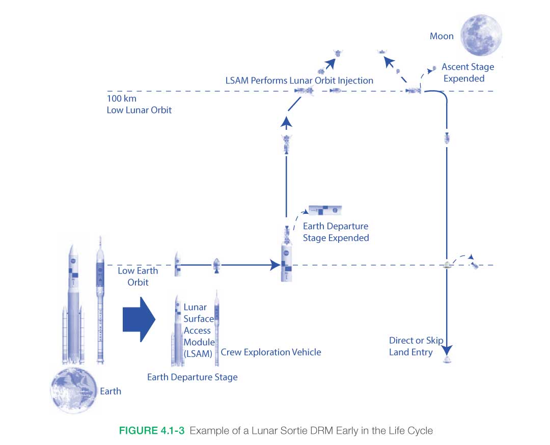
The ConOps should consider all aspects of operations including nominal and off-nominal operations during integration, test, and launch through disposal. Typical information contained in the ConOps includes a description of the major phases; operation timelines; operational scenarios and/or DRM (see Figure 4.1-3 for an example of a DRM); fault management strategies, description of human interaction and required training, end-to-end communications strategy; command and data architecture; operational facilities; integrated logistic support (resupply, maintenance, and assembly); staffing levels and required skill sets; and critical events. The operational scenarios describe the dynamic view of the systems’ operations and include how the system is perceived to function throughout the various modes and mode transitions, including interactions with external interfaces, response to anticipated hazard and faults, and during failure mitigations. For exploration missions, multiple DRMs make up a ConOps. The design and performance analysis leading to the requirements should satisfy all of them.
Additional information on the development of the ConOps is discussed in Section 4.1.2.1 of the NASA Expanded Guidance for Systems Engineering document found at https://nen.nasa.gov/web/se/doc-repository.
Appendix S contains one possible outline for developing a ConOps. The specific sections of the ConOps will vary depending on the scope and purpose of the project.
Concept of Operations vs. Operations Concept
Concept of Operations
Developed early in Pre-Phase A by the technical team, describes the overall high-level concept of how the system will be used to meet stakeholder expectations, usually in a time sequenced manner. It describes the system from an operational perspective and helps facilitate an understanding of the system goals. It stimulates the development of the requirements and architecture related to the user elements of the system. It serves as the basis for subsequent definition documents and provides the foundation for the long-range operational planning activities.
Operations Concept
A description of how the flight system and the ground system are used together to ensure that the concept of operation is reasonable. This might include how mission data of interest, such as engineering or scientific data, are captured, returned to Earth, processed, made available to users, and archived for future reference. It is typically developed by the operational team. (See NPR 7120.5.)
4.1.1.2.5 Define Stakeholder Expectations in Acceptable Statements
Once the ConOps has been developed, any gaps or ambiguities have been resolved, and understanding between the technical team and stakeholders about what is expected/intended for the system/product has been achieved, the expectations can be formally documented. This often comes in the form of NGOs, mission success criteria, and design drivers. These may be captured in a document, spreadsheet, model, or other form appropriate to the product.
The design drivers will be strongly dependent upon the ConOps, including the operational environment, orbit, and mission duration requirements. For science missions, the design drivers include, at a minimum, the mission launch date, duration, and orbit, as well as operational considerations. If alternative orbits are to be considered, a separate concept is needed for each orbit. Exploration missions should consider the destination, duration, operational sequence (and system configuration changes), crew interactions, maintenance and repair activities, required training, and in situ exploration activities that allow the exploration to succeed.
4.1.1.2.6 Analyze Expectations Statements for Measures of Effectiveness
The mission success criteria define what the mission needs to accomplish to be successful. This could be in the form of science missions, exploration concept for human exploration missions, or a technological goal for technology demonstration missions. The success criteria also define how well the concept measurements or exploration activities should be accomplished. The success criteria capture the stakeholder expectations and, along with programmatic requirements and constraints, are used within the high-level requirements.
Measures of Effectiveness (MOEs) are the measures of success that are designed to correspond to accomplishment of the system objectives as defined by the stakeholder’s expectations. They are stated from the stakeholder’s point of view and represent criteria that are to be met in order for the stakeholder to consider the project successful. As such, they can be synonymous with mission/project success criteria. MOEs are developed when the NGOs or other stakeholder expectation documentation is developed. Additional information on MOEs is contained in Section 6.7.2.4 of the NASA Expanded Guidance for SE document at https://nen.nasa.gov/web/se/doc-repository.
4.1.1.2.7 Validate That Defined Expectation Statements Reflect Bidirectional Traceability
The NGOs or other stakeholder expectation documentation should also capture the source of the expectation. Depending on the location within the product layer, the expectation may be traced to an NGO or a requirement of a higher layer product, to organizational strategic plans, or other sources. Later functions and requirements will be traced to these NGOs. The use of a requirements management tool or model or other application is particularly useful in capturing and tracing expectations and requirements.
4.1.1.2.8 Obtain Stakeholder Commitments to the Validated Set of Expectations
Once the stakeholder and the technical team are in agreement with the expressed stakeholder expectations and the concept of operations, signatures or other forms of commitment are obtained. In order to obtain these commitments, a concept review is typically held on a formal or informal basis depending on the scope and complexity of the system (see Section 6.7). The stakeholder expectations (e.g., NGOs), MOEs, and concept of operations are presented, discussed, and refined as necessary to achieve final agreement. This agreement shows that both sides have committed to the development of this product.
4.1.1.2.9 Baseline Stakeholder Expectations
The set of stakeholder expectations (e.g., NGOs and MOEs) and the concept of operations that are agreed upon are now baselined. Any further changes will be required to go through a formal or informal (depending on the nature of the product) approval process involving both the stakeholder and the technical team.
4.1.1.2.10 Capture Work Products
In addition to developing, documenting, and baselining stakeholder expectations, the ConOps and MOEs discussed above and other work products from this process should be captured. These may include key decisions made, supporting decision rationale and assumptions, and lessons learned in performing these activities.
4.1.1.3 Outputs
Typical outputs for capturing stakeholder expectations include the following:
- Validated Stakeholder Expectations: These are the agreed-to set of expectations for this product layer. They are typically captured in the form of needs, goals, and objectives with constraints and assumptions identified. They may also be in the form of models or other graphical forms.
- Concept of Operations: The ConOps describes how the system will be operated during the life cycle phases that will meet stakeholder expectations. It describes the system characteristics from an operational perspective and helps facilitate an understanding of the system goals and objectives and other stakeholder expectations. Examples would be the ConOps document, model, or a Design Reference Mission (DRM).
- Enabling Product Support Strategies: These include any special provisions that might be needed for fabrication, test, deployment, operations sustainment, and disposal of the end product. They identify what support will be needed and any enabling products that will need to be developed in order to generate the end product.
- Measures of Effectiveness: A set of MOEs is developed based on the stakeholder expectations. These are measures that represent expectations that are critical to the success of the system, and failure to satisfy these measures will cause the stakeholder to deem the system unacceptable.
Other outputs that might be generated:
- Human/Systems Function Allocation: This describes the interaction of the hardware and software systems with all personnel and their supporting infrastructure. In many designs (e.g., human space flight) human operators are a critical total-system component and the roles and responsibilities of the humans-in-the-system should be clearly understood. This should include all human/system interactions required for a mission including assembly, ground operations, logistics, in-flight and ground maintenance, in-flight operations, etc.
4.1.2 Stakeholder Expectations Definition Guidance
Refer to Section 4.1.2 in the NASA Expanded Guidance for Systems Engineering at https://nen.nasa.gov/web/se/doc-repository for additional guidance on:
- Concept of Operations (including examples),
- protection of space assets, and
- identification of stakeholders for each phase.
4.2 Technical Requirements Definition
Note: It is important to note that the team must not rely solely on the requirements received to design and build the system. Communication and iteration with the relevant stakeholders are essential to ensure a mutual understanding of each requirement. Otherwise, the designers run the risk of misunderstanding and implementing an unwanted solution to a different interpretation of the requirements. This iterative stakeholder communication is a critically important part of project validation. Always confirm that the right products and results are being developed.
The Technical Requirements Definition Process transforms the stakeholder expectations into a definition of the problem and then into a complete set of validated technical requirements expressed as “shall” statements that can be used for defining a design solution for the Product Breakdown Structure (PBS) and related enabling products. The process of requirements definition is a recursive and iterative one that develops the stakeholders’ requirements, product requirements, and lower level product/component requirements. The requirements should enable the description of all inputs, outputs, and required relationships between inputs and outputs, including constraints, and system interactions with operators, maintainers, and other systems. The requirements documents organize and communicate requirements to the customer and other stakeholders and the technical community.
Technical requirements definition activities apply to the definition of all technical requirements from the program, project, and system levels down to the lowest level product/component requirements document.
4.2.1 Process Description
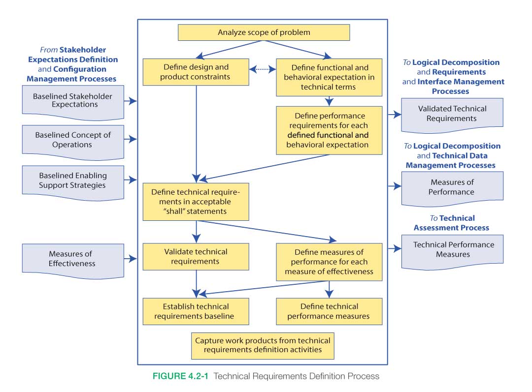
Figure 4.2-1 provides a typical flow diagram for the Technical Requirements Definition Process and identifies typical inputs, outputs, and activities to consider in addressing technical requirements definition.
4.2.1.1 Inputs
Typical inputs needed for the requirements process include the following:
- Baselined Stakeholder Expectations: This is the agreed-to set of stakeholder expectations (e.g., needs, goals, objectives, assumptions, constraints, external interfaces) for the product(s) of this product layer.
- Baselined Concept of Operations: This describes how the system will be operated during the life cycle phases to meet stakeholder expectations. It describes the system characteristics from an operational perspective and helps facilitate an understanding of the system goals, objectives, and constraints. It includes scenarios, use cases, and/or Design Reference Missions (DRMs) as appropriate for the project. It may be in the form of a document, graphics, videos, models, and/or simulations.
- Baselined Enabling Support Strategies: These describe the enabling products that were identified in the Stakeholder Expectations Definition Process as needed to develop, test, produce, operate, or dispose of the end product. They also include descriptions of how the end product will be supported throughout the life cycle.
- Measures of Effectiveness: These MOEs were identified during the Stakeholder Expectations Definition Process as measures that the stakeholders deemed necessary to meet in order for the project to be considered a success (i.e., to meet success criteria).
Other inputs that might be useful in determining the technical requirements:
- Human/Systems Function Allocation: This describes the interaction of the hardware and software systems with all personnel and their supporting infrastructure. When human operators are a critical total-system component, the roles and responsibilities of the humans-in-the-system should be clearly understood. This should include all human/system interactions required for a mission including assembly, ground operations, logistics, in-flight and ground maintenance, in-flight operations, etc.
4.2.1.2 Process Activities
4.2.1.2.1 Define Constraints, Functional and Behavioral Expectations
The top-level requirements and expectations are initially assessed to understand the technical problem to be solved (scope of the problem) and establish the design boundary. This boundary is typically established by performing the following activities:
- Defining constraints that the design needs to adhere to or that limit how the system will be used. The constraints typically cannot be changed based on trade-off analyses.
- Identifying those elements that are already under design control and cannot be changed. This helps establish those areas where further trades will be made to narrow potential design solutions.
- Identifying external and enabling systems with which the system should interact and establishing physical and functional interfaces (e.g., mechanical, electrical, thermal, human, etc.).
- Defining functional and behavioral expectations for the range of anticipated uses of the system as identified in the ConOps. The ConOps describes how the system will be operated and the possible use-case scenarios.
4.2.1.2.2 Define Requirements
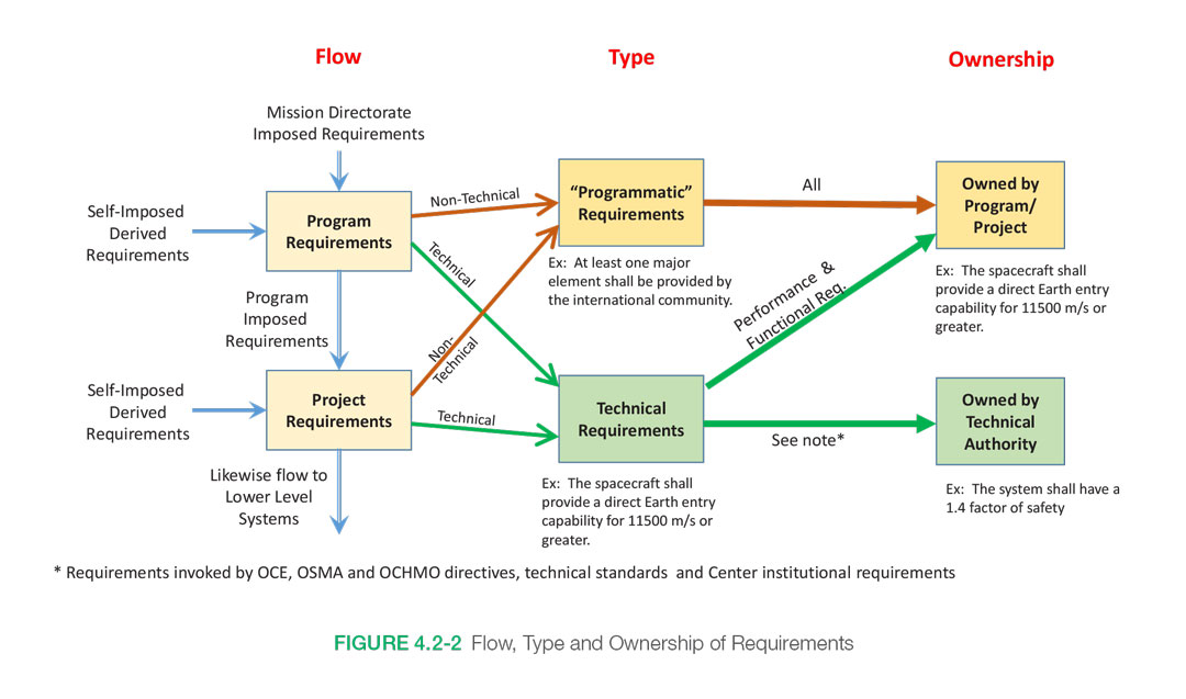
A complete set of project requirements includes those that are decomposed and allocated down to design elements through the PBS and those that cut across product boundaries. Requirements allocated to the PBS can be functional requirements (what functions need to be performed), performance requirements (how well these functions should be performed), and interface requirements (product to product interaction requirements). Crosscutting requirements include environmental, safety, human factors, and those that originate from the “-ilities” and from Design and Construction (D&C) standards. Figure 4.2-2 is a general overview on the flow of requirements, what they are called, and who is responsible (owns) for approving waivers.
- Functional requirements define what functions need to be performed to accomplish the objectives.
- Performance requirements define how well the system needs to perform the functions.
With an overall understanding of the constraints, physical/functional interfaces, and functional/behavioral expectations, the requirements can be further defined by establishing performance and other technical criteria. The expected performance is expressed as a quantitative measure to indicate how well each product function needs to be accomplished.
Note: Requirements can be generated from non-obvious stakeholders and may not directly support the current mission and its objectives, but instead provide an opportunity to gain additional benefits or information that can support the Agency or the Nation. Early in the process, the systems engineer can help identify potential areas where the system can be used to collect unique information that is not directly related to the primary mission. Often outside groups are not aware of the system goals and capabilities until it is almost too late in the process.
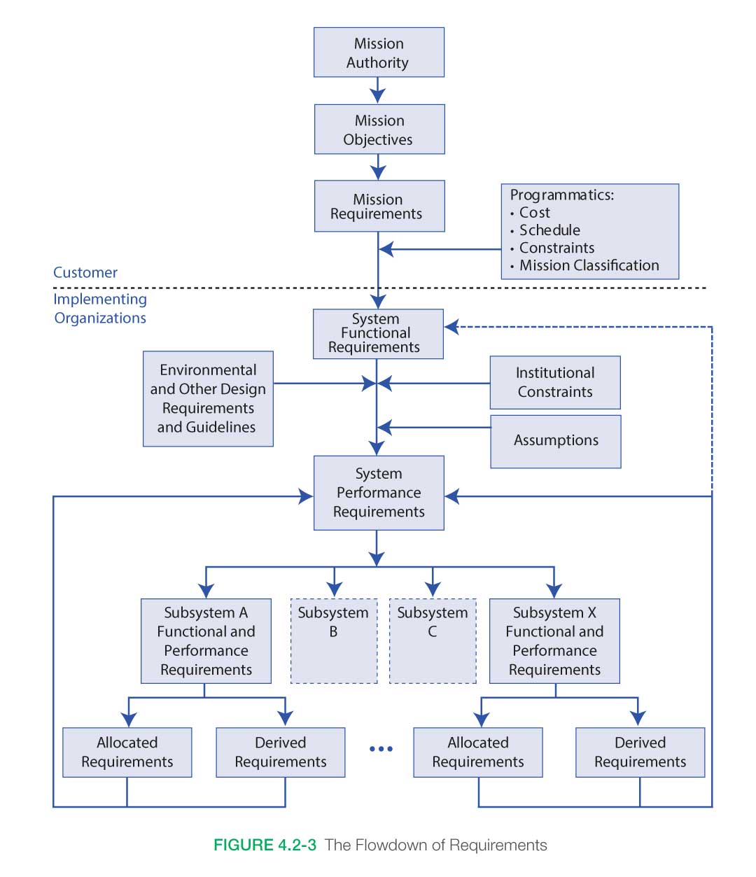
Technical requirements come from a number of sources including functional, performance, interface, environmental, safety, human interfaces, standards and in support of the “’ilities” such as reliability, sustainability, producibility and others. Consideration and inclusion of all types of requirements is needed in order to form a complete and consistent set of technical requirements from which the system will be architected and designed. Figure 4.2-3 shows an example of parent and child requirement flowdown.
Example of Functional and Performance Requirements
Initial Function Statement
The Thrust Vector Controller (TVC) shall provide vehicle control about the pitch and yaw axes.
This statement describes a high-level function that the TVC must perform. The technical team needs to transform this statement into a set of design-to functional and performance requirements.
Functional Requirements with Associated Performance Requirements
- The TVC shall gimbal the engine a maximum of 9 degrees, ± 0.1 degree.
- The TVC shall gimbal the engine at a maximum rate of 5 degrees/second ± 0.3 degrees/second.
- The TVC shall provide a force of 40,000 pounds, ± 500 pounds.
- The TVC shall have a frequency response of 20 Hz, ± 0.1 Hz.
4.2.1.2.3 Define Requirements in Acceptable Statements
Finally, the requirements should be defined in acceptable “shall” statements, which are complete sentences with a single “shall” per statement. Rationale for the requirement should also be captured to ensure the reason and context of the requirement is understood. The Key Driving Requirements (KDRs) should be identified. These are requirements that can have a large impact on cost or schedule when implemented. A KDR can have any priority or criticality. Knowing the impact that a KDR has on the design allows better management of requirements.
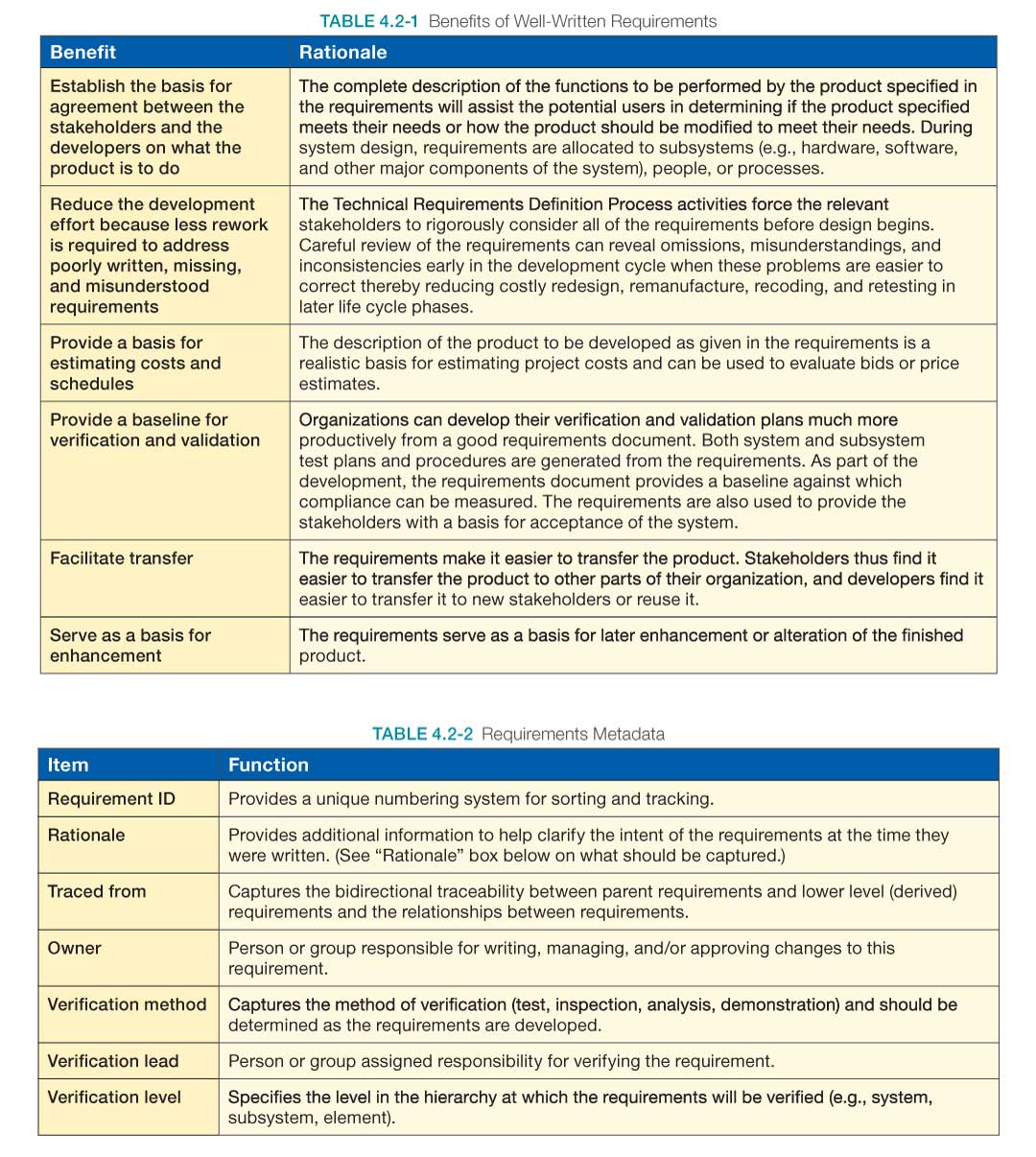
See Appendix C for guidance and a checklist on how to write good requirements and Appendix E for validating requirements. A well-written requirements document provides several specific benefits to both the stakeholders and the technical team as shown in Table 4.2-1.
It is useful to capture information about each of the requirements, called metadata, for future reference and use. Many requirements management tools will request or have options for storing this type of information. Table 4.2-2 provides examples of the types of metadata that might be useful.
Rationale
The rationale should be kept up to date and include the following information:
- Reason for the Requirement: Often the reason for the requirement is not obvious, and it may be lost if not recorded as the requirement is being documented. The reason may point to a constraint or concept of operations. If there is a clear parent requirement or trade study that explains the reason, then it should be referenced.
- Document Assumptions: If a requirement was written assuming the completion of a technology development program or a successful technology mission, the assumption should be documented.
- Document Relationships: The relationships with the product’s expected operations (e.g., expectations about how stakeholders will use a product) should be documented. This may be done with a link to the ConOps.
- Document Design Constraints: Constraints imposed by the results from decisions made as the design evolves should be documented. If the requirement states a method of implementation, the rationale should state why the decision was made to limit the solution to this one method of implementation.
4.2.1.2.4 Validate Technical Requirements
An important part of requirements definition is the validation of the requirements against the stakeholder expectations, the mission objectives and constraints, the concept of operations, and the mission success criteria. Validating requirements can be broken into six steps:
- Are the Requirements Written Correctly? Identify and correct requirements “shall” statement format errors and editorial errors.
- Are the Requirements Technically Correct? A few trained reviewers from the technical team identify and remove as many technical errors as possible before having all the relevant stakeholders review the requirements. The reviewers should check that the requirement statements (a) have bidirectional traceability to the baselined stakeholder expectations; (b) were formed using valid assumptions; and (c) are essential to and consistent with designing and realizing the appropriate product solution form that will satisfy the applicable product life cycle phase success criteria.
- Do the Requirements Satisfy Stakeholders? All relevant stakeholder groups identify and remove defects.
- Are the Requirements Feasible? All requirements should make technical sense and be possible to achieve.
- Are the Requirements Verifiable? All requirements should be stated in a fashion and with enough information that it will be possible to verify the requirement after the end product is implemented.
- Are the Requirements Redundant or Over-specified? All requirements should be unique (not redundant to other requirements) and necessary to meet the required functions, performance, or behaviors.
Requirements validation results are often a deciding factor in whether to proceed with the next process of Logical Decomposition or Design Solution Definition. The project team should be prepared to: (1) demonstrate that the project requirements are complete and understandable; (2) demonstrate that evaluation criteria are consistent with requirements and the operations and logistics concepts; (3) confirm that requirements and MOEs are consistent with stakeholder needs; (4) demonstrate that operations and architecture concepts support mission needs, goals, objectives, assumptions, guidelines, and constraints; and (5) demonstrate that the process for managing change in requirements is established, documented in the project information repository, and communicated to stakeholders.
4.2.1.2.5 Define MOPs and TPMs
Measures of Performance (MOPs) define the performance characteristics that the system should exhibit when fielded and operated in its intended environment. MOPs are derived from the MOEs but are stated in more technical terms from the supplier’s point of view. Typically, multiple MOPs, which are quantitative and measurable, are needed to satisfy a MOE, which can be qualitative. From a verification and acceptance point of view, MOPs reflect the system characteristics deemed necessary to achieve the MOEs.
Technical Performance Measures (TPMs) are physical or functional characteristics of the system associated with or established from the MOPs that are deemed critical or key to mission success. The TPMs are monitored during implementation by comparing the current actual achievement or best estimate of the parameters with the values that were anticipated for the current time and projected for future dates. They are used to confirm progress and identify deficiencies that might jeopardize meeting a critical system requirement or put the project at cost or schedule risk.
For additional information on MOPs and TPMs, their relationship to each other and MOEs, and examples of each, see Section 6.7.2.6.2 of the NASA Expanded Guidance for SE document at https://nen.nasa.gov/web/se/doc-repository.
4.2.1.2.6 Establish Technical Requirement Baseline
Once the technical requirements are identified and validated to be good (clear, correct, complete, and achievable) requirements, and agreement has been gained by the customer and key stakeholders, they are baselined and placed under configuration control. Typically, a System Requirements Review (SRR) is held to allow comments on any needed changes and to gain agreement on the set of requirements so that it may be subsequently baselined. For additional information on the SRR, see Section 6.7.
4.2.1.2.7 Capture Work Products
The work products generated during the above activities should be captured along with key decisions that were made, any supporting decision rationale and assumptions, and lessons learned in performing these activities.
4.2.1.3 Outputs
- Validated Technical Requirements: This is the approved set of requirements that represents a complete description of the problem to be solved and requirements that have been validated and approved by the customer and stakeholders. Examples of documents that capture the requirements are a System Requirements Document (SRD), Project Requirements Document (PRD), Interface Requirements Document (IRD), and a Software Requirements Specification (SRS).
- Measures of Performance: These are the identified quantitative measures that, when met by the design solution, help ensure that one or more MOEs will be satisfied. There may be two or more MOPs for each MOE. See Section 6.7.2.6.2 in the NASA Expanded Guidance for Systems Engineering at https://nen.nasa.gov/web/se/doc-repository for further details.
- Technical Performance Measures: These are the set of performance measures that are monitored and trended by comparing the current actual achievement of the parameters with that expected or required at the time. TPMs are used to confirm progress and identify deficiencies. See Section 6.7.2.6.2 in the NASA Expanded Guidance for Systems Engineering at https://nen.nasa.gov/web/se/doc-repository for further details.
4.2.2 Technical Requirements Definition Guidance
Refer to Section 4.2.2 of the NASA Expanded Guidance for SE document at https://nen.nasa.gov/web/se/doc-repository for additional information on:
- types of requirements,
- requirements databases, and
- the use of technical standards.
4.3 Logical Decomposition
Logical decomposition is the process for creating the detailed functional requirements that enable NASA programs and projects to meet the stakeholder expectations. This process identifies the “what” that should be achieved by the system at each level to enable a successful project. Logical decomposition utilizes functional analysis to create a system architecture and to decompose top-level (or parent) requirements and allocate them down to the lowest desired levels of the project.
The Logical Decomposition Process is used to:
- Improve understanding of the defined technical requirements and the relationships among the requirements (e.g., functional, performance, behavioral, and temporal etc.), and
- Decompose the parent requirements into a set of logical decomposition models and their associated sets of derived technical requirements for input to the Design Solution Definition Process.
4.3.1 Process Description
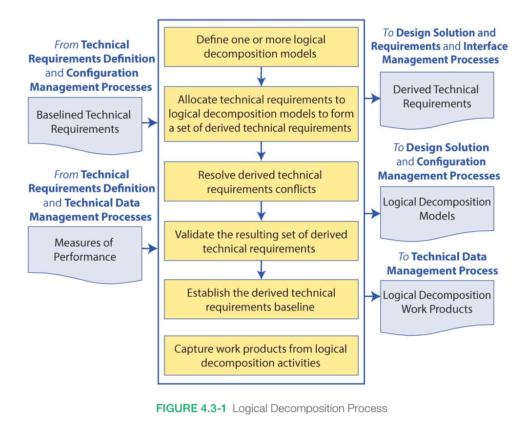
Figure 4.3-1 provides a typical flow diagram for the Logical Decomposition Process and identifies typical inputs, outputs, and activities to consider in addressing logical decomposition
4.3.1.1 Inputs
Typical inputs needed for the Logical Decomposition Process include the following:
- Technical Requirements: A validated set of requirements that represent a description of the problem to be solved, have been established by functional and performance analysis, and have been approved by the customer and other stakeholders. Examples of documents that capture the requirements are an SRD, PRD, and IRD.
- Technical Measures: An established set of measures based on the expectations and requirements that will be tracked and assessed to determine overall system or product effectiveness and customer satisfaction. These measures are MOEs, MOPs, and a special subset of these called TPMs. See Section 6.7.2.6.2 in the NASA Expanded Guidance for Systems Engineering at https://nen.nasa.gov/web/se/doc-repository for further details.
4.3.1.2 Process Activities
4.3.1.2.1 Define One or More Logical Decomposition Models
The key first step in the Logical Decomposition Process is establishing the system architecture model. The system architecture activity defines the underlying structure and relationships of hardware, software, humans-in-the-loop, support personnel, communications, operations, etc., that provide for the implementation of Agency, mission directorate, program, project, and subsequent levels of the requirements. System architecture activities drive the partitioning of system elements and requirements to lower level functions and requirements to the point that design work can be accomplished. Interfaces and relationships between partitioned subsystems and elements are defined as well.
Once the top-level (or parent) functional requirements and constraints have been established, the system designer uses functional analysis to begin to formulate a conceptual system architecture. The system architecture can be seen as the strategic organization of the functional elements of the system, laid out to enable the roles, relationships, dependencies, and interfaces between elements to be clearly defined and understood. It is strategic in its focus on the overarching structure of the system and how its elements fit together to contribute to the whole, instead of on the particular workings of the elements themselves. It enables the elements to be developed separately from each other while ensuring that they work together effectively to achieve the top-level (or parent) requirements.
Much like the other elements of functional decomposition, the development of a good system-level architecture is a creative, recursive, collaborative, and iterative process that combines an excellent understanding of the project’s end objectives and constraints with an equally good knowledge of various potential technical means of delivering the end products.
Focusing on the project’s ends, top-level (or parent) requirements, and constraints, the system architect should develop at least one, but preferably multiple, concept architectures capable of achieving program objectives. Each architecture concept involves specification of the functional elements (what the pieces do), their relationships to each other (interface definition), and the ConOps, i.e., how the various segments, subsystems, elements, personnel, units, etc., will operate as a system when distributed by location and environment from the start of operations to the end of the mission.
The development process for the architectural concepts should be recursive and iterative with feedback from stakeholders and external reviewers, as well as from subsystem designers and operators, provided as often as possible to increase the likelihood of effectively achieving the program’s desired ends while reducing the likelihood of cost and schedule overruns.
In the early stages of development, multiple concepts are generated. Cost and schedule constraints will ultimately limit how long a program or project can maintain multiple architectural concepts. For all NASA programs, architecture design is completed during the Formulation Phase. For most NASA projects (and tightly coupled programs), the baselining of a single architecture happens during Phase A. Architectural changes at higher levels occasionally occur as decomposition to lower levels produces complexity in design, cost, or schedule that necessitates such changes. However, as noted in Figure 2.5-1, the later in the development process that changes occur, the more expensive they become.
Aside from the creative minds of the architects, there are multiple tools that can be utilized to develop a system’s architecture. These are primarily modeling and simulation tools, functional analysis tools, architecture frameworks, and trade studies. (For example, one way of doing architecture is the Department of Defense (DOD) Architecture Framework (DODAF). A search concept is developed, and analytical models of the architecture, its elements, and their operations are developed with increased fidelity as the project evolves. Functional decomposition, requirements development, and trade studies are subsequently undertaken. Multiple iterations of these activities feed back to the evolving architectural concept as the requirements flow down and the design matures.
4.3.1.2.2 Allocate Technical Requirements, Resolve Conflicts, and Baseline
Functional analysis is the primary method used in system architecture development and functional requirement decomposition. It is the systematic process of identifying, describing, and relating the functions a system should perform to fulfill its goals and objectives. Functional analysis identifies and links system functions, trade studies, interface characteristics, and rationales to requirements. It is usually based on the ConOps for the system of interest.
Three key steps in performing functional analysis are:
- Translate top-level requirements into functions that should be performed to accomplish the requirements.
- Decompose and allocate the functions to lower levels of the product breakdown structure.
- Identify and describe functional and subsystem interfaces.
The process involves analyzing each system requirement to identify all of the functions that need to be performed to meet the requirement. Each function identified is described in terms of inputs, outputs, failure modes, consequence of failure, and interface requirements. The process is repeated from the top down so that sub-functions are recognized as part of larger functional areas. Functions are arranged in a logical sequence so that any specified operational usage of the system can be traced in an end-to-end path.
The process is recursive and iterative and continues until all desired levels of the architecture/system have been analyzed, defined, and baselined. There will almost certainly be alternative ways to decompose functions. For example, there may be several ways to communicate with the crew: Radio Frequency (RF), laser, Internet, etc. Therefore, the outcome is highly dependent on the creativity, skills, and experience of the engineers doing the analysis. As the analysis proceeds to lower levels of the architecture and system, and the system is better understood, the systems engineer should keep an open mind and a willingness to go back and change previously established architecture and system requirements. These changes will then have to be decomposed down through the architecture and sub-functions again with the recursive process continuing until the system is fully defined with all of the requirements understood and known to be viable, verifiable, and internally consistent. Only at that point should the system architecture and requirements be baselined.
4.3.1.2.3 Capture Work Products
The other work products generated during the Logical Decomposition Process should be captured along with key decisions made, supporting decision rationale and assumptions, and lessons learned in performing the activities.
4.3.1.3 Outputs
Typical outputs of the Logical Decomposition Process include the following:
- Logical Decomposition Models: These models define the relationship of the requirements and functions and their behaviors. They include the system architecture models that define the underlying structure and relationship of the elements of the system (e.g., hardware, software, humans-in-the-loop, support personnel, communications, operations, etc.) and the basis for the partitioning of requirements into lower levels to the point that design work can be accomplished.
- Derived Technical Requirements: These are requirements that arise from the definitions of the selected architecture that were not explicitly stated in the baselined requirements that served as an input to this process. Both the baselined and derived requirements are allocated to the system architecture and functions.
- Logical Decomposition Work Products: These are the other products generated by the activities of this process.
4.3.2 Logical Decomposition Guidance
Refer to Section 4.3.2 and Appendix F in the NASA Expanded Guidance for Systems Engineering at https://nen.nasa.gov/web/se/doc-repository for additional guidance on:
- Product Breakdown Structures and
- Functional Analysis Techniques.
4.4 Design Solution Definition
The Design Solution Definition Process is used to translate the high-level requirements derived from the stakeholder expectations and the outputs of the Logical Decomposition Process into a design solution. This involves transforming the defined logical decomposition models and their associated sets of derived technical requirements into alternative solutions. These alternative solutions are then analyzed through detailed trade studies that result in the selection of a preferred alternative. This preferred alternative is then fully defined into a final design solution that satisfies the technical requirements. This design solution definition is used to generate the end product specifications that are used to produce the product and to conduct product verification. This process may be further refined depending on whether there are additional subsystems of the end product that need to be defined.
4.4.1 Process Description
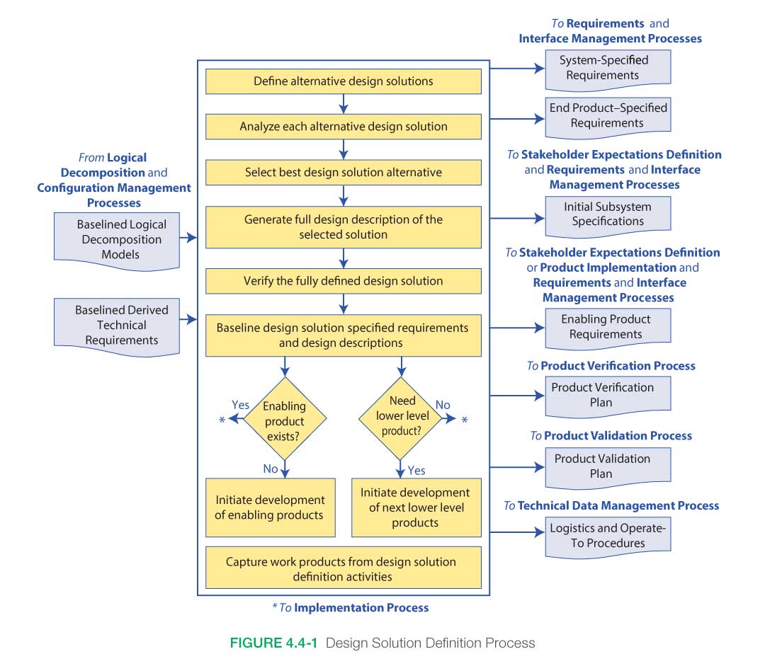
Figure 4.4-1 provides a typical flow diagram for the Design Solution Definition Process and identifies typical inputs, outputs, and activities to consider in addressing design solution definition.
4.4.1.1 Inputs
There are several fundamental inputs needed to initiate the Design Solution Definition Process:
- Technical Requirements: These are the customer and stakeholder needs that have been translated into a complete set of validated requirements for the system, including all interface requirements.
- Logical Decomposition Models: Requirements are analyzed and decomposed by one or more different methods (e.g., function, time, behavior, data flow, states, modes, system architecture, etc.) in order to gain a more comprehensive understanding of their interaction and behaviors. (See the definition of a model in Appendix B.)
4.4.1.2 Process Activities
4.4.1.2.1 Define Alternative Design Solutions
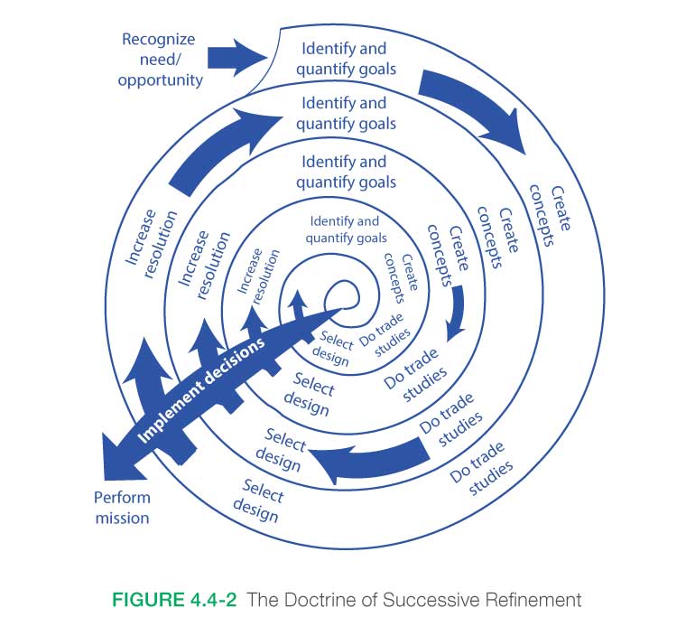
The realization of a system over its life cycle involves a succession of decisions among alternative courses of action. If the alternatives are precisely defined and thoroughly understood to be well differentiated in the cost-effectiveness space, then the systems engineer can make choices among them with confidence.
To obtain assessments that are crisp enough to facilitate good decisions, it is often necessary to delve more deeply into the space of possible designs than has yet been done, as illustrated in Figure 4.4-2. It should be realized, however, that this illustration represents neither the project life cycle, which encompasses the system development process from inception through disposal, nor the product development process by which the system design is developed and implemented.
Each “create concepts” step in Figure 4.4-2 involves a recursive and iterative design loop driven by the set of stakeholder expectations where a straw man architecture/design, the associated ConOps, and the derived requirements are developed and programmatic constraints such as cost and schedule are considered. These three products should be consistent with each other and will require iterations and design decisions to achieve this consistency. This recursive and iterative design loop is illustrated in Figure 4.0-1.
Each “create concepts” step in Figure 4.4-2 also involves an assessment of potential capabilities offered by the continually changing state of technology and potential pitfalls captured through experience-based review of prior program/project lessons learned data. It is imperative that there be a continual interaction between the technology development process, crosscutting processes such as human systems integration, and the design process to ensure that the design reflects the realities of the available technology and that overreliance on immature technology is avoided. Additionally, the state of any technology that is considered enabling should be properly monitored, and care should be taken when assessing the impact of this technology on the concept performance. This interaction is facilitated through a periodic assessment of the design with respect to the maturity of the technology required to implement the design. (See Section 4.4.2.1 in the NASA Expanded Guidance for Systems Engineering at https://nen.nasa.gov/web/se/doc-repository for a more detailed discussion of technology assessment.) These technology elements usually exist at a lower level in the PBS. Although the process of design concept development by the integration of lower level elements is a part of the systems engineering process, there is always a danger that the top-down process cannot keep up with the bottom-up process. Therefore, system architecture issues need to be resolved early so that the system can be modeled with sufficient realism to do reliable trade studies.
As the system is realized, its particulars become clearer—but also harder to change. See the rising “Cost to Change Design Direction” in Figure 2.5‑1. The purpose of systems engineering is to make sure that the Design Solution Definition Process happens in a way that leads to the most functional, safe, and cost-effective final system while working within any given schedule boundaries. The basic idea is that before those decisions that are hard to undo are made, the alternatives should be carefully and iteratively assessed, particularly with respect both to the maturity of the required technology and to stakeholder expectations for efficient, effective operations.
4.4.1.2.2 Create Alternative Design Concepts
Once it is understood what the system is to accomplish, it is possible to devise a variety of ways that those goals can be met. Sometimes, that comes about as a consequence of considering alternative functional allocations and integrating available subsystem design options, all of which can have technologies at varying degrees of maturity. Ideally, as wide a range of plausible alternatives as is consistent with the design organization’s charter should be defined, keeping in mind the current stage in the process of successive refinement. When the bottom-up process is operating, a problem for the systems engineer is that the designers tend to become fond of the designs they create, so they lose their objectivity; the systems engineer should stay an “outsider” so that there is more objectivity. This is particularly true in the assessment of the technological maturity of the subsystems and components required for implementation. There is a tendency on the part of technology developers and project management to overestimate the maturity and applicability of a technology that is required to implement a design. This is especially true of “heritage” equipment. The result is that critical aspects of systems engineering are often overlooked.
The creation of alternative design solutions involves assessment of potential capabilities offered by the continually changing state of technology. A continual interaction between the technology development process and the design process ensures that the design reflects the realities of the available technology. This interaction is facilitated through periodic assessment of the design with respect to the maturity of the technology required to implement the design.
After identifying the technology gaps existing in a given design concept, it is frequently necessary to undertake technology development in order to ascertain viability. Given that resources will always be limited, it is necessary to pursue only the most promising technologies that are required to enable a given concept.
If requirements are defined without fully understanding the resources required to accomplish needed technology developments, then the program/project is at risk. Technology assessment should be done iteratively until requirements and available resources are aligned within an acceptable risk posture. Technology development plays a far greater role in the life cycle of a program/project than has been traditionally considered, and it is the role of the systems engineer to develop an understanding of the extent of program/project impacts—maximizing benefits and minimizing adverse effects. Traditionally, from a program/project perspective, technology development has been associated with the development and incorporation of any “new” technology necessary to meet requirements. However, a frequently overlooked area is that associated with the modification of “heritage” systems incorporated into different architectures and operating in different environments from the ones for which they were designed. If the required modifications and/or operating environments fall outside the realm of experience, then these too should be considered technology development.
To understand whether or not technology development is required—and to subsequently quantify the associated cost, schedule, and risk—it is necessary to systematically assess the maturity of each system, subsystem, or component in terms of the architecture and operational environment. It is then necessary to assess what is required in the way of development to advance the maturity to a point where it can successfully be incorporated within cost, schedule, and performance constraints. A process for accomplishing this assessment is described in Appendix G. Because technology development has the potential for such significant impacts on a program/project, technology assessment needs to play a role throughout the design and development process from concept development through Preliminary Design Review (PDR). Lessons learned from a technology development point of view should then be captured in the final phase of the program.
On the first turn of the successive refinement in Figure 4.4-2, the subject is often general approaches or strategies, sometimes architectural concepts. On the next, it is likely to be functional design, then detailed design, and so on. The reason for avoiding a premature focus on a single design is to permit discovery of the truly best design. Part of the systems engineer’s job is to ensure that the design concepts to be compared take into account all interface requirements. Characteristic questions include: “Did you include the cabling?” or “Did you consider how the maintainers can repair the system?” When possible, each design concept should be described in terms of controllable design parameters so that each represents as wide a class of designs as is reasonable. In doing so, the systems engineer should keep in mind that the potentials for change may include organizational structure, personnel constraints, schedules, procedures, and any of the other things that make up a system. When possible, constraints should also be described by parameters.
4.4.1.2.3 Analyze Each Alternative Design Solution
The technical team analyzes how well each of the design alternatives meets the system objectives (technology gaps, effectiveness, technical achievability, performance, cost, schedule, and risk, both quantified and otherwise). This assessment is accomplished through the use of trade studies. The purpose of the trade study process is to ensure that the system architecture, intended operations (i.e., the ConOps) and design decisions move toward the best solution that can be achieved with the available resources. The basic steps in that process are:
- Devise some alternative means to meet the functional requirements. In the early phases of the project life cycle, this means focusing on system architectures; in later phases, emphasis is given to system designs.
- Evaluate these alternatives in terms of the MOPs and system life cycle cost. Mathematical models are useful in this step not only for forcing recognition of the relationships among the outcome variables, but also for helping to determine what the MOPs should be quantitatively.
- Rank the alternatives according to appropriate selection criteria.
- Drop less promising alternatives and proceed to the next level of resolution, if needed.
The trade study process should be done openly and inclusively. While quantitative techniques and rules are used, subjectivity also plays a significant role. To make the process work effectively, participants should have open minds, and individuals with different skills—systems engineers, design engineers, crosscutting specialty discipline and domain engineers, program analysts, system end users, decision scientists, maintainers, operators, and project managers—should cooperate. The right quantitative methods and selection criteria should be used. Trade study assumptions, models, and results should be documented as part of the project archives. The participants should remain focused on the functional requirements, including those for enabling products. For an in-depth discussion of the trade study process, see Section 6.8. The ability to perform these studies is enhanced by the development of system models that relate the design parameters to those assessments, but it does not depend upon them.
The technical team should consider a broad range of concepts when developing the system model. The model should define the roles of crew, operators, maintainers, logistics, hardware, and software in the system. It should identify the critical technologies required to implement the mission and should consider the entire life cycle from fabrication to disposal. Evaluation criteria for selecting concepts should be established. Cost is always a limiting factor. However, other criteria, such as time to develop and certify a unit, risk, and reliability, also are critical. This stage cannot be accomplished without addressing the roles of operators and maintainers. These contribute significantly to life cycle costs and to the system reliability. Reliability analysis should be performed based upon estimates of component failure rates for hardware and an understanding of the consequences of these failures. If probabilistic risk assessment models are applied, it may be necessary to include occurrence rates or probabilities for software faults or human error events. These models should include hazard analyses and controls implemented through fault management. Assessments of the maturity of the required technology should be done and a technology development plan developed.
Controlled modification and development of design concepts, together with such system models, often permits the use of formal optimization techniques to find regions of the design space that warrant further investigation.
Whether system models are used or not, the design concepts are developed, modified, reassessed, and compared against competing alternatives in a closed-loop process that seeks the best choices for further development. System and subsystem sizes are often determined during the trade studies. The end result is the determination of bounds on the relative cost-effectiveness of the design alternatives, measured in terms of the quantified system goals. (Only bounds, rather than final values, are possible because determination of the final details of the design is intentionally deferred.) Increasing detail associated with the continually improving resolution reduces the spread between upper and lower bounds as the process proceeds.
4.4.1.2.4 Select the Best Design Solution Alternative
The technical team selects the best design solution from among the alternative design concepts, taking into account subjective factors that the team was unable to quantify, such as robustness, as well as estimates of how well the alternatives meet the quantitative requirements; the maturity of the available technology; and any effectiveness, cost, schedule, risk, or other constraints.
The Decision Analysis Process, as described in Section 6.8, should be used to make an evaluation of the alternative design concepts and to recommend the “best” design solution.
When it is possible, it is usually well worth the trouble to develop a mathematical expression, called an “objective function,” that expresses the values of combinations of possible outcomes as a single measure of cost-effectiveness, as illustrated in Figure 4.4-3, even if both cost and effectiveness should be described by more than one measure.

Note: The different shaded areas indicate different levels of uncertainty. Dashed lines represent constant values of objective function (cost-effectiveness). Higher values of cost-effectiveness are achieved by moving toward upper left. A, B, and C are design concepts with different risk patterns.
The objective function (or “cost function”) assigns a real number to candidate solutions or “feasible solutions” in the alternative space or “search space.” A feasible solution that minimizes (or maximizes, if that is the goal) the objective function is called an “optimal solution.” When achievement of the goals can be quantitatively expressed by such an objective function, designs can be compared in terms of their value. Risks associated with design concepts can cause these evaluations to be somewhat nebulous because they are uncertain and are best described by probability distributions.
In Figure 4.4-3, the risks are relatively high for design concept A. There is little risk in either effectiveness or cost for concept B, while the risk of an expensive failure is high for concept C, as is shown by the cloud of probability near the x axis with a high cost and essentially no effectiveness. Schedule factors may affect the effectiveness and cost values and the risk distributions.
The mission success criteria for systems differ significantly. In some cases, effectiveness goals may be much more important than all others. Other projects may demand low costs, have an immutable schedule, or require minimization of some kinds of risks. Rarely (if ever) is it possible to produce a combined quantitative measure that relates all of the important factors, even if it is expressed as a vector with several components. Even when that can be done, it is essential that the underlying actors and relationships be thoroughly revealed to and understood by the systems engineer. The systems engineer should weigh the importance of the unquantifiable factors along with the quantitative data.
Technical reviews of the data and analyses, including technology maturity assessments, are an important part of the decision support packages prepared for the technical team. The decisions that are made are generally entered into the configuration management system as changes to (or elaborations of) the system baseline. The supporting trade studies are archived for future use. An essential feature of the systems engineering process is that trade studies are performed before decisions are made. They can then be baselined with much more confidence.
4.4.1.2.5 Increase the Resolution of the Design
The successive refinement process of Figure 4.4-2 illustrates a continuing refinement of the system design. At each level of decomposition, the baselined derived (and allocated) requirements become the set of high-level requirements for the decomposed elements, and the process begins again. One might ask, “When do we stop refining the design?” The answer is that the design effort proceeds to a depth that is sufficient to meet several needs: the design should penetrate sufficiently to allow analytical validation of the design to the requirements and ConOps; it should also have sufficient depth to support cost and operations modeling and to convince a review team of a feasible design with performance, cost, and risk margins.
The systems engineering engine is applied again and again as the system is developed. As the system is realized, the issues addressed evolve and the particulars of the activity change. Most of the major system decisions (goals, architecture, acceptable life cycle cost, etc.) are made during the early phases of the project, so the successive refinements do not correspond precisely to the phases of the system life cycle. Much of the system architecture can be seen even at the outset, so the successive refinements do not correspond exactly to development of the architectural hierarchy either. Rather, they correspond to the successively greater resolution by which the system is defined.
It is reasonable to expect the system to be defined with better resolution as time passes. This tendency is formalized at some point (in Phase B) by defining a baseline system definition. Usually, the goals, objectives, and constraints are baselined as the requirements portion of the baseline. The entire baseline is then placed under configuration control in an attempt to ensure that any subsequent changes are indeed justified and affordable.
At this point in the systems engineering process, there is a logical branch point. For those issues for which the process of successive refinement has proceeded far enough, the next step is to implement the decisions at that level of resolution. For those issues that are still insufficiently resolved, the next step is to refine the development further.
4.4.1.2.6 Fully Describe the Design Solution
Once the preferred design alternative has been selected and the proper level of refinement has been completed, then the design is fully defined into a final design solution that will satisfy the technical requirements and ConOps. The design solution definition will be used to generate the end product specifications that will be used to produce the product and to conduct product verification. This process may be further refined depending on whether there are additional subsystems of the end product that need to be defined.
The scope and content of the full design description should be appropriate for the product life cycle phase, the phase success criteria, and the product position in the PBS (system structure). Depending on these factors, the form of the design solution definition could be simply a simulation model or a paper study report. The technical data package evolves from phase to phase, starting with conceptual sketches or models and ending with complete drawings, parts list, and other details needed for product implementation or product integration. Typical output definitions from the Design Solution Definition Process are shown in Figure 4.4-1 and are described in Section 4.4.1.3.
4.4.1.2.7 Verify the Design Solution
Once an acceptable design solution has been selected from among the various alternative designs and documented in a technical data package, the design solution should next be verified against the system requirements and constraints. A method to achieve this verification is by means of a peer review to evaluate the resulting design solution definition. Guidelines for conducting a peer review are discussed in Section 6.7.2.4.5.
In addition, peer reviews play a significant role as a detailed technical component of higher level technical and programmatic reviews. For example, the peer review of a component battery design can go into much more technical detail on the battery than the integrated power subsystem review. Peer reviews can cover the components of a subsystem down to the level appropriate for verifying the design against the requirements. Concerns raised at the peer review might have implications on the power subsystem design and verification and therefore should be reported at the next higher level review of the power subsystem.
The verification should show that the design solution definition:
- Is realizable within the constraints imposed on the technical effort;
- Has specified requirements that are stated in acceptable statements and have bidirectional traceability with the technical requirements and stakeholder expectations; and
- Has decisions and assumptions made in forming the solution consistent with its set of technical requirements and identified system product and service constraints.
This design solution verification is in contrast to the verification of the end product described in the end product verification plan which is part of the technical data package. That verification occurs in a later life cycle phase and is a result of the Product Verification Process (see Section 5.3) applied to the realization of the design solution as an end product.
4.4.1.2.8 Validate the Design Solution
The validation of the design solution is a recursive and iterative process as shown in Figure 4.0-1. Each alternative design concept is validated against the set of stakeholder expectations. The stakeholder expectations drive the iterative design loop in which a straw man architecture/design, the ConOps, and the derived requirements are developed. These three products should be consistent with each other and will require iterations and design decisions to achieve this consistency. Once consistency is achieved, functional analyses allow the study team to validate the design against the stakeholder expectations. A simplified validation asks the questions: Does the system work as expected? How does the system respond to failures, faults, and anomalies? Is the system affordable? If the answer to any of these questions is no, then changes to the design or stakeholder expectations will be required, and the process is started over again. This process continues until the system—architecture, ConOps, and requirements—meets the stakeholder expectations.
This design solution validation is in contrast to the validation of the end product described in the end-product validation plan, which is part of the technical data package. That validation occurs in a later life cycle phase and is a result of the Product Validation Process (see Section 5.4) applied to the realization of the design solution as an end product.
4.4.1.2.9 Identify Enabling Products
Enabling products are the life cycle support products and services (e.g., production, test, deployment, training, maintenance, and disposal) that facilitate the progression and use of the operational end product through its life cycle. Since the end product and its enabling products are interdependent, they are viewed as a system. Project responsibility thus extends to responsibility for acquiring services from the relevant enabling products in each life cycle phase. When a suitable enabling product does not already exist, the project that is responsible for the end product can also be responsible for creating and using the enabling product.
Therefore, an important activity in the Design Solution Definition Process is the identification of the enabling products and personnel that will be required during the life cycle of the selected design solution and then initiating the acquisition or development of those enabling products and personnel. Need dates for the enabling products should be realistically identified on the project schedules, incorporating appropriate schedule slack. Then firm commitments in the form of contracts, agreements, and/or operational plans should be put in place to ensure that the enabling products will be available when needed to support the product life cycle phase activities. The enabling product requirements are documented as part of the technical data package for the Design Solution Definition Process.
An environmental test chamber is an example of an enabling product whose use would be acquired at an appropriate time during the test phase of a space flight system.
Special test fixtures or special mechanical handling devices are examples of enabling products that would have to be created by the project. Because of long development times as well as oversubscribed facilities, it is important to identify enabling products and secure the commitments for them as early in the design phase as possible.
4.4.1.2.10 Baseline the Design Solution
As shown earlier in Figure 4.0-1, once the selected system design solution meets the stakeholder expectations, the study team baselines the products and prepares for the next life cycle phase. Because of the recursive nature of successive refinement, intermediate levels of decomposition are often validated and baselined as part of the process. In the next level of decomposition, the baselined requirements become the set of high-level requirements for the decomposed elements, and the process begins again.
Baselining a particular design solution enables the technical team to focus on one design out of all the alternative design concepts. This is a critical point in the design process. It puts a stake in the ground and gets everyone on the design team focused on the same concept. When dealing with complex systems, it is difficult for team members to design their portion of the system if the system design is a moving target. The baselined design is documented and placed under configuration control. This includes the system requirements, specifications, and configuration descriptions.
While baselining a design is beneficial to the design process, there is a danger if it is exercised too early in the Design Solution Definition Process. The early exploration of alternative designs should be free and open to a wide range of ideas, concepts, and implementations. Baselining too early takes the inventive nature out of the concept exploration. Therefore, baselining should be one of the last steps in the Design Solution Definition Process.
4.4.1.3 Outputs
Outputs of the Design Solution Definition Process are the specifications and plans that are passed on to the product realization processes. They contain the design-to, build-to, train-to, and code-to documentation that complies with the approved baseline for the system.
As mentioned earlier, the scope and content of the full design description should be appropriate for the product life cycle phase, the phase success criteria, and the product position in the PBS.
Outputs of the Design Solution Definition Process include the following:
- The System Specification: The system specification contains the functional baseline for the system that is the result of the Design Solution Definition Process. The system design specification provides sufficient guidance, constraints, and system requirements for the design engineers to begin developing the design.
- The System External Interface Specifications: The system external interface specifications describe the functional baseline for the behavior and characteristics of all physical interfaces that the system has with the external world. These include all structural, thermal, electrical, and signal interfaces, as well as the human-system interfaces.
- The End-Product Specifications: The end-product specifications contain the detailed build-to and code-to requirements for the end product. They are detailed, exact statements of design particulars, such as statements prescribing materials, dimensions, and quality of work to build, install, or manufacture the end product.
- The End-Product Interface Specifications: The end-product interface specifications contain the detailed build-to and code-to requirements for the behavior and characteristics of all logical and physical interfaces that the end product has with external elements, including the human-system interfaces.
- Initial Subsystem Specifications: The end-product subsystem initial specifications provide detailed information on subsystems if they are required.
- Enabling Product Requirements: The requirements for associated supporting enabling products provide details of all enabling products. Enabling products are the life cycle support products, infrastructures, personnel, logistics, and services that facilitate the progression and use of the operational end product through its life cycle. They are viewed as part of the system since the end product and its enabling products are interdependent.
- Product Verification Plan: The end-product verification plan (generated through the Technical Planning Process) provides the content and depth of detail necessary to provide full visibility of all verification activities for the end product. Depending on the scope of the end product, the plan encompasses qualification, acceptance, prelaunch, operational, and disposal verification activities for flight hardware and software.
- Product Validation Plan: The end-product validation plan (generated through the Technical Planning Process) provides the content and depth of detail necessary to provide full visibility of all activities to validate the end product against the baselined stakeholder expectations. The plan identifies the type of validation, the validation procedures, and the validation environment that are appropriate to confirm that the realized end product conforms to stakeholder expectations.
- Logistics and Operate-to Procedures: The applicable logistics and operate-to procedures for the system describe such things as handling, transportation, maintenance, long-term storage, and operational considerations for the particular design solution.
Other outputs may include:
- Human Systems Integration Plan: The system HSI Plan should be updated to indicate the numbers, skills, and development (i.e., training) required for humans throughout the full life cycle deployment and operations of the system.
4.4.2 Design Solution Definition Guidance
Refer to Section 4.4.2 in the NASA Expanded Guidance for Systems Engineering at https://nen.nasa.gov/web/se/doc-repository for additional guidance on:
- technology assessment,
- human capability assessment, and
- integrating engineering specialties into the SE process.