


![Request for Information – Potential [Placeholder for Prize]](https://assets.science.nasa.gov/dynamicimage/assets/science/missions/a-step/FFR_Earth_Background_20251120%20.png?w=1024)


Materials & Structures Subsystems
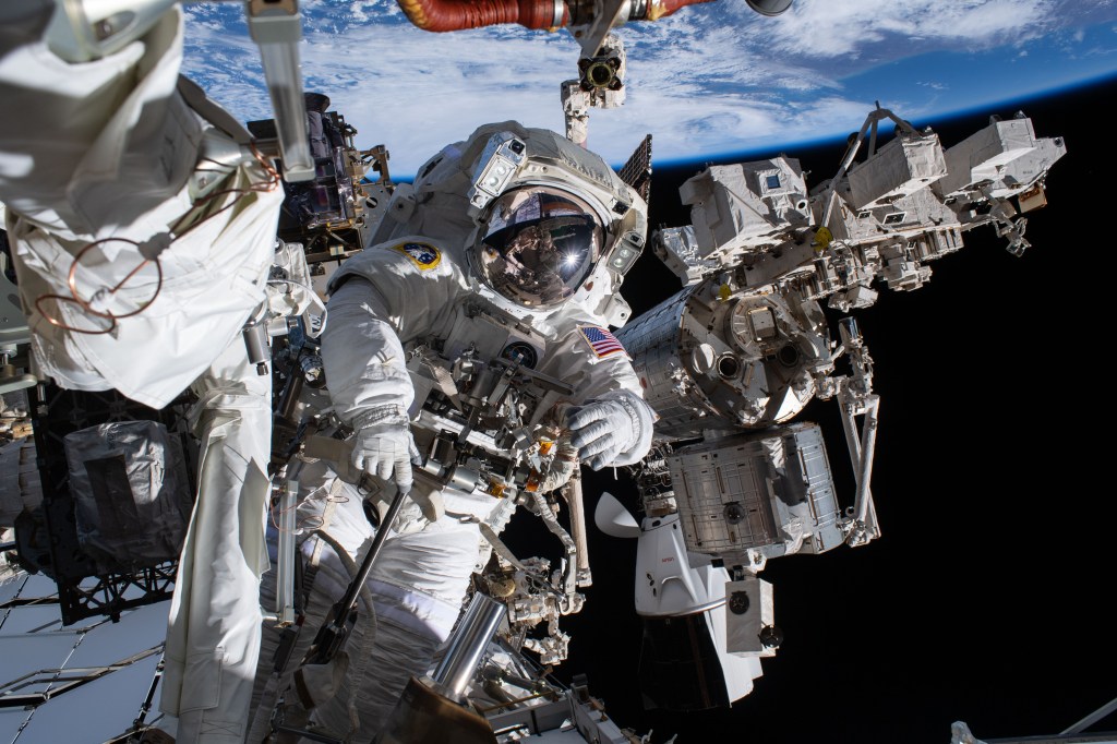
Structures and materials are pivotal for human spaceflight as they ensure the integrity, reliability, and safety of spacecraft, habitats, and equipment, providing the foundation for successful missions in the demanding and varied conditions of space. Johnson Space Center (JSC) has worldclass capabilities and unique expertise in structures design and development, analysis, testing and materials evaluation, damage and assessments. JSC has extensive experience in the design and development of space vehicle mating attachment systems and light weight hatches, windows, inflatable structures and traditional structures.
JSC materials laboratories provide analytical capabilities used in the analysis and evolution of space flight hardware. Test and evaluation capabilities include metallography, material properties testing, microscopy, environmental testing, nondestructive evaluation and analytical chemistry. JSC offers expertise in development, evaluation and testing of metallics, polymers, composite materials, and textile and insulation materials. JSC experts provide structural static and fatigue load testing for payloads and spacecraft structures. Tests range from mechanical properties testing of materials to full-scale verification testing of payloads and spacecraft structures. Structural testing facilities provide the capability to perform test and evaluation of both aerospace and non-aerospace hardware.
The White Sands Test Facility (WSTF) Materials and Components Laboratories Office has unique and comprehensive test capabilities to evaluate material and component behaviors in hazardous environments. Tests performed routinely include materials properties determination, materials compatibility and toxicity analyses, detonation studies, flight article outgassing characterization, systems analysis, orbital debris impact simulation testing and propellant characterization.
JSC and WSTF fabrication facilities provide the resources, materials and labor necessary to produce quality flight, ground support and prototype hardware. This includes experience and expertise in precision machining, sheet metal, welding, cleaning, hydrostatic testing, coatings, soft goods, metal finishing, models and plastics, and assembly. We invite our partners to be at the forefront of aerospace innovation and success by leveraging our extensive capabilities in structures, materials, and advanced technologies, pushing the boundaries of space exploration.
Structural Testing
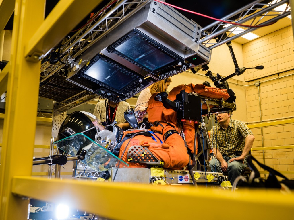
Structures Test Laboratory – Dynamic
The Structures Test Facility (STL) at NASA’s Johnson Space Center (JSC) houses a wide range of structural testing capabilities designed to evaluate aerospace components, subsystems, and full-scale structures under flight representative environments. These capabilities support the development, qualification, and certification of spacecraft systems for human spaceflight and other mission-critical applications. These structural test specialties enables the STL to validate critical spaceflight hardware from small-scale components to large integrated systems while ensuring safety, performance, and reliability for crewed and uncrewed missions. Key specialties include:
- Load Testing & Structural Verification – Static and fatigue load testing of components and large structures, including manned spacecraft hardware, to verify strength, stiffness, and design margins.
- Vibration Testing – Random vibration, and sine sweep load testing to simulate launch and ascent environments.
- Fracture Mechanics & Fatigue – Advanced crack growth monitoring, strain gauge instrumentation, and life-cycle fatigue testing of metals, composites, and other aerospace materials.
- Data Acquisition & Analysis – High-fidelity measurement systems with synchronized strain, load, displacement, and acceleration data for detailed structural response evaluation.
Structures Test Laboratory – Static
The Structures Test Facility provides structural static strength and fatigue load testing of spaceflight hardware to ensure that functionality is not impaired by severe launch and landing environments. Tests range from mechanical properties testing of materials to full-scale verification testing of payloads and spacecraft structures. JSC is equipped with a variety of hydraulic and electromechanical load frames with maximum load capacities ranging from 10 to 220 kip. JSC also provides for nondestructive evaluation of hardware utilizing x-ray, ultrasonic, fluorescent penetrant, magnetic particle, infrared thermography and eddy current techniques. Structural testing facilities provide capability to perform test and evaluation of both aerospace and non-aerospace hardware.
- Static and fatigue load testing using single or multiple actuators up to 220,000 lb.
- Tension and compression testing – load or displacement control
- Cyclic testing up to 100 Hz
- Fracture mechanics property testing
- Creep testing
- Pressure testing
- Tensile, lap shear, and compression testing of materials at low and elevated temperatures
- Instrumentation
- Strain, load, deflection, pressure, velocity, acceleration, thermocouples
- Twelve load frames can be operated in tension and compression and either load or displacement control
- Cyclic testing up to 100 Hz, depending on the load and stroke
- Ten load frames can be configured for fracture mechanics property testing, including automated da/dN testing
- Actuators are controlled up to 6 stroke or 32 load control channels or any combination of both
- Sizable inventory of linear resistive deflection potentiometers, displacement and velocity transducers, LVDT deflection transducers, RVDT angular displacement transducers, thermocouples, and force washers
Structures Design & Development
Softgoods and Materials Assessment
The Softgoods Lab (SGL) in the Engineering Design and Analysis Branch/EC2 of the Crew and Thermal Systems Division designs, develops, and manufactures flight softgoods products and components. The SGL also designs and fabricates ground support, test, and prototype softgoods products. The Advanced Materials Lab (AML) in the same branch provides testing for developing & evaluating textile fabrics and other non-metallic materials such as plastic, polymer films, foil, mylar, mesh, elastomers, and adhesives for NASA & industry applications. This lab is equipped to evaluate and certify softgoods materials and products for spaceflight.
The focus of the labs is developing customers’ needs and ideas into prototypes, which are then evaluated and customized to produce flight items that meet or exceed their requirements. Examples of softgoods products that are produced by the Softgoods Lab and evaluated by the Advanced Materials Lab: Components for spacesuits, softgoods containers for EVA and IVA operations, emergency masks, cargo stowage containers and kits, inflatable structures, bladders and liquid containment, contamination blankets, multi-layer insulation thermal blankets, crew clothing, and crew sleep accommodations.
Crewed Inflatable Softgoods
NASA has extensive experience, history, and technical lessons learned from decades of development on Crewed Inflatable Softgoods. This expertise is available to partners to support design, modeling, analysis, and testing of inflatable softgoods structures.
- Expertise in design, development, and testing of in-space and surface inflatable softgoods including habitats, airlocks, and pressurized transfer tunnels
- Structural design and sizing of restraint layer for crewed inflatable elements
- Test support with high-speed video and digital image correlation systems
- Component level tensile testing capability for material evaluation, stitch/seam evaluation, and short-term creep testing on webbing, cordage, and threads
- Assembly level testing capability including ultimate burst, creep, damage tolerance, leak, and packaging/deployment – available both in free air and thermal vacuum chambers
- Restraint layer structural health monitoring evaluation techniques and tools
- Material testing of softgoods including cold temperature flexure
- Softgoods standards, requirements, and specifications development
Technical test data and lessons learned are available to partners, which includes:
- Air Barrier Seal Interface Development Report
- Air Barrier Cold Flexure Material Data Report
- Integrated Window Interface Design and Strap Sizing
- Restraint Webbing Tapered Diamond Stitch Methods
- Softgoods Shell Folding Technique and Fabric Sizing
- Softgoods Shell Hypervelocity Impact Testing Report
- Softgoods Shell Thermal Vacuum Testing Report
- Sub-scale Assembly Modal Testing Report
Spacecraft Glass & Windows
On-site expertise and face to face training classes are available for successful design, modeling, analysis, and testing of spacecraft windows. NASA also encourages use of the Window Material Database that is used to characterize window materials for the spaceflight environment in a standardized way to facilitate window design trades.
- Standardized processes, procedures, facilities, personnel and material thicknesses (0.5”) will be used for characterization
- Allows for an apples-to-apples comparison between performance parameters for different materials
- Data is collected by objective NASA personnel
- No concerns for mismatched testing methodologies between materials
- No concerns for supplier creative marketing departments
- Enables designers to pursue innovative and integrated window subsystem designs and to optimally match mission requirements to window materials
- Will enable challenging future mission scenarios such as long duration habitats
- Will enable lightweight window subsystems
- Spaceflight relevant environments will be applied to characterize material performance, with parameters chosen based upon window design requirements needs
- The database is intended to be publicly released for use in the spaceflight industry
- Data will be stored in a publicly accessible database
- In the interim (while data is being developed), data will be made available to designers upon request
Crew Hatches & External Doors
NASA JSC provides design, development, test and evaluation (DDT&E) of hatch and external door systems. Crew Hatches & External Doors expertise is available for successful design, modeling, analysis, testing, and manufacturing of crew hatches and external doors.
Component, Subsystem and Vehicle-level Systems Engineering and Integration
- Analytical Simulation/Prediction, Independent Modeling and Model Validation
- Dynamic, Static, and Natural/Induced Environmental Testing
- System Management, Flight Hardware Acceptance, Joint Integrated Testing
- Standards and Specifications Development
- Avionics, Software and Controls
- Rapid Prototyping and Evaluation
- Contact Modeling and Simulation
- Collaborative Working Environment
Structural Engineering Domain Work Area (SEDWA)
The Structural Engineering Domain Work Area (SEDWA) provides a research and development environment for docking, deployable structures, external doors, hatches, spacecraft windows, and thermal protection.
SEDWA has 3 work areas:
- The Electro-Mechanical Development Area used to conduct R&D on docking, deployable structures, external doors, and hatches
- The Spacecraft Window Inspection laboratory is used to explore, develop, and test materials used in the fabrication of space windows. It is also used to properly process spacecraft window flight hardware, and for hands on window handling training
- The Home for Entry Decent & Landing Assembly and Testing (HEAT) which tests and develops material for the next generation of human spaceflight vehicle thermal protection
Integrated Coupled Loads Analysis
Integrated Coupled Loads Analysis expertise is available for successful in-space modeling, coupled loads analysis, and environments development of integrated vehicles.
- In-space modeling, coupled loads analysis, and environments development of integrated vehicles (i.e., rendezvous, docking/undocking, berthing/unberthing, mated ops, ACS, reboost, EVA/IVA, exercise, plume impingement)
- Analytical Simulation/Prediction, Independent Modeling and Model Validation
- Standards and Specifications Development
Materials Evaluation, Damage & Assessments
Softgoods and Materials Assessment
The Softgoods Lab, under the supervision of the Engineering Design and Analysis Branch, designs, develops, and manufactures flight softgoods components. They also design and fabricate ground support, test, and prototype softgoods. The designers collaborate with project engineers to define the requirements for EVA and IVA projects and establish specifications to fulfill them.
The focus of the lab is developing customers’ needs and ideas into prototypes, which are then evaluated and customized to produce flight items that meet or exceed their requirements. The Advanced Materials Lab provides testing for developing & evaluating these materials for NASA & industry applications. This lab is equipped to evaluate materials, including textiles, coated structures, polymer films, foams, elastomers, papers, & adhesives.
Analytical Chemistry Lab (ACL)
NASA JSC Materials Evaluation Labs (MEL) Analytical Chemistry Lab (ACL) contains analytical instruments used to determine different material properties, identify contaminants and unknowns, and aid in the development of new materials.
- Fourier transform infrared spectrometry (FTIR)
- Pyrolysis gas chromatography/mass spectrometry (GCMS)
- Differential scanning calorimetry (DSC)
- Thermogravimetric analysis (TGA)
- Dynamic mechanical analysis (DMA)
- Thermal mechanical analyzer (TMA)
- Rheology and optical instruments for emissivity and absorptivity
Metallography (MET) Lab
NASA JSC Materials Evaluation Labs (MEL) Metallography (MET) Lab performs as-received digital photography, cutting, mounting, and polishing of specimens, and photo-documentation of material microstructures during support of various failure analyses.
- Abrasive cut-off and precision diamond saws
- Microhardness and standard hardness testing
- Optical microscopy with inverted, stereo, and upright microscopes
- Dimensional analysis
Non-destructive Evaluation (NDE) Lab
NASA JSC Materials Evaluation Labs (MEL) Non-destructive Evaluation (NDE) Lab provides surface and volumetric evaluations using nondestructive test methods and techniques that do not destroy the hardware. Experts assist in failure analysis investigations, reverse engineering, and manufacturing of metallic and nonmetallic materials. The Non-destructive Evaluation (NDE) Lab views the internal workings of a part without cutting or further damage.
Radiographic Testing
- Computed Tomography
- Digital Radiography
- Standard Film Radiography
- Ultrasonic Testing (UT) - Phased Array UT, C-scan UT, Conventional UT
- Infrared (IR) Thermography Inspection
- Flash Infrared Thermography Testing
- Remote Evaluation Techniques
- Laser Shearography
- High Speed Imagery
- Eddy Current Testing (ET) – Array Eddy Current Testing, Conventional ET
- Liquid Penetrant Testing and Magnetic Particle Testing Inspection – fluorescent and visible mediums for both methods
Polymer Lab
NASA JSC Materials Evaluation Labs (MEL) Polymer Lab can perform tensile, compressive and lap shear testing of different materials at elevated or cold temperatures and composite bonding and sample preparation for structural material developmental testing.
- Tests include tension, compression, shear and bending, plus controlled impact damage tolerance evaluation
- Electro-mechanical load frame (150kN) with environmental chamber
- Temperature range -250° F to 600° F
- Variable light weight impact tester for composites
Scanning Electron Microscopy (SEM) Lab
NASA JSC Materials Evaluation Labs (MEL) Scanning Electron Microscopy (SEM) Lab performs the high-resolution imagery down to 1 nm and elemental chemical analysis on conductive and non-conductive materials in support of failure analyses and material development.
The Scanning Electron Microscopy (SEM) Lab captures high magnification images with identification of surface elements. Capabilities include a variable pressure scanning electron microscope with energy dispersive spectroscopy.
Odor & Offgas Flight Acceptance and Standard Testing (FAST)
White Sands Test Facility conducts odor testing and offgas testing. The facilities detect, identify, and quantify all gaseous compounds and odors released from a material or article under human habitable atmospheric conditions. Human evaluation of odors can also be performed.
Four trained and certified analytical chemists to identify and quantify all offgassed products
Analytical Capabilities
- Two Gas Chromatographs (GC) equipped with Fourier transform infrared (FTIR) detectors and mass spectrometers (MS) for detecting and quantifying offgassed inorganic and organic compounds
- One GC equipped with a Flame Ionization Detector (FID) for detecting and quantifying offgassed organic compounds
- One GC equipped with a methanizer coupled to a FID for detecting and quantifying carbon monoxide and methane
- One GC equipped with a thermal conductivity detector (TCD) for detecting and quantifying hydrogen
- Simulated-use testing conducted in two airtight gloveboxes
- Handling of electrostatic discharge (ESD) components. Class 1 ESD protective workstation available
- Test small to very large materials and components. A large array of offgassing chambers to fit most any size material or test article (2 L through 86700 L) are maintained for testing. Our largest offgassing chamber is the CVI® self-heating cylindrical offgassing chamber. This chamber is 1.83 m (6 ft) in diameter and 2.74 m (9 ft) long. This chamber can achieve vacuums as low as 1.33 Pa (1 × 10⁻² torr), with a temperature range from ambient ~ 21 to 93°C (70 to 200°F).
- Thermal conditioning capabilities range from ~21 to 316 °C (~70 to 600°F). Five thermal conditioning ovens (incorporating multiple temperature measurement systems) are connected to an automatic alarm system to notify personnel of power outages and/or temperature nonconformities. Ovens can handle the entire size range of sample chambers.
- Odor Test Panel maintained and tested for odor testing (Test 6). An “Odor Mission” is conducted by five certified odor panel members under the direction of an Odor Panel Test Conductor. These five odor panel members are selected randomly out of a pool of all odor panel members and their sense of smell tested to ensure sensitivity.
- On-site state-of-the-art test article/material preparation and analytical laboratories with full sample preparation, measurement, thermal conditioning, and chemical analysis capabilities are maintained.
- A secure, limited-access storage area for spaceflight items and other high cost/importance items is utilized
- Direct test data entry and storage into a secure, laboratory information and tracking system that automatically generates the reports for review and transmittal is maintained
- Materials and equipment to handle heavy and bulky articles up to 909 Kg (2000 lb.) (heavier with prior notification), are available. In addition to a full rack, sized to hold test articles in the 3 m (10 ft) by 1.8 m (6 ft) chamber.
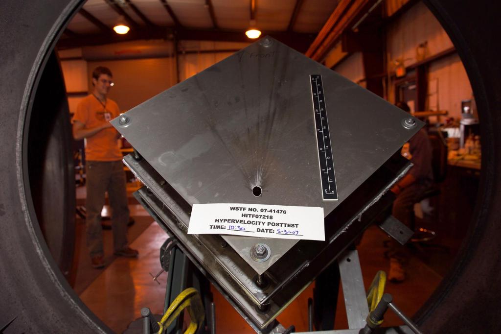
Micrometeoroid and Orbital Debris (MMOD) Testing
The White Sands Test Facility’s Remote Hypervelocity Test Laboratory (RHTL) is an access‐controlled hazardous test area capable of simulating Micrometeoroid and Orbital Debris (MMOD) impacts. This unique NASA facility was designed to safely handle and test hazardous targets, and simulate impacts on shields, spacecraft, satellites, and spacesuits.
- Three different caliber gun ranges; 1 inch, .50 caliber, and .17 caliber guns able to propel single 0.05 mm to 22.2 mm diameter projectiles with velocities in excess of 7.5 km/s
- The facility is remotely located with access control protocols and underground bunkers for personnel protection
- Various high speed cameras are used, some capable of 200 million frames per second, to capture the target impact and debris cloud
- Ability to measure projectile velocity with laser intervalometers
- High-speed data acquisition to capture the diagnostic information from the light detectors and temperature, pressure, and shock measurement sensors
- Ability to test hazardous test articles (energized, pressurized, toxic materials, pyrotechnics, etc.)
Composite Overwrapped Pressure Vessels
White Sands Test Facility (WSTF) tests and evaluates composite overwrap pressure vessels (COPVs) and components through studying damage tolerance and stress rupture. It also offers leading expertise in both destructive and nondestructive evaluation, training, analysis, and development of life extension protocols for composite structures.
White Sands Test Facility (WSTF) offers leading expertise in the testing, nondestructive evaluation, training, and analysis of composite structures. WSTF engages in the test and evaluation of structures by performing mechanical damage tests, sustained load testing, material compatibility, and hydraulic and pneumatic burst tests to understand and evaluate environmental effects on pressurized systems.
Damage Detection Course
A two-day damage detection course is offered to qualify aerospace visual inspectors of flight composite pressure vessels and provides comprehensive working knowledge of composite overwrap pressure vessel (COPV) technology. The course focuses specifically on mechanical damage, safe life, sustained load, and propellant/fuel exposure effects on pressure vessels built using graphite/epoxy composite filament wound onto metallic liners.
Propellants and Aerospace Fluids Testing and Analysis
White Sands Test Facility (WSTF) performs testing that enables aerospace fluid and propulsion system designers to evaluate the risks and hazards associated with potential and existing materials, components, and system configurations.
The WSTF performs laboratory-scale experiments and tests to determine and verify the properties of aerospace fluids. Tests include micro-calorimetry and accelerated rate calorimetry, flash point, fire point, differential scanning calorimetry, inductively coupled plasma-mass spectroscopy (ICP-MS), Fourier transform infrared spectroscopy (FTIR), adiabatic compression, and thermal runaway. Testing is performed on exposed and nonexposed materials per applicable NASA, military, and American Society for Testing and Materials (ASTM) standards to determine how fluid exposure affects the material’s properties. Testing can consist of exposure to any of the fluids and properties can vary depending on the type of material being evaluated (soft good, metal, ceramic, lubricant, or other materials). Testing includes tensile strength, flexure, compression set, and hardness. Composition and glass transition temperature are tested when polymers are the subject material. Posttest analysis of fluids is performed after exposure to determine how material exposure may affect fluid specifications and performance. WSTF designs free-field blast experiments up to 230-kilogram (kg) trinitrotoluene (TNT) equivalency and small-scale experiments to assess the hazards associated with a variety of high-energy release mechanisms. These energy releases can be the result of thermochemical reaction, such as with explosives and propellants; the rupture of gas or fluid storage vessels at high pressures, or both. WSTF hydrogen test facilities are designed to allow gaseous tests to be conducted at pressures up to 6,000 psi and at flow rates up to 5 pounds per second. Materials and component tests can be conducted with hydrogen in both the gaseous and liquid state. WSTF can provide in-person training to personnel handling hypergolic propellants, oxygen, and hydrogen medias. Classes are tailored to the individual audience and can vary from intense classroom discussions of new chemical analytical techniques to field training with Level-A, totally encapsulating suits (TES).
Related Patents
Diamond Maker Technology Simulates Alien Geology in Laboratories
Enhanced Software Suite Maximizes Non-Destructive Evaluation (NDE) Methods
Related Software
MicroStructPy – A Microstructure Mesh Generator for Heterogeneous Materials


Connect With Us
Whether you are a public agency, private company, or academic institution, we look forward to hearing from you. Fill out the Statement of Interest form to submit your inquiry.