


Home
Characteristics
Quick Facts
Capabilities
Flight Loads Laboratory Characteristics
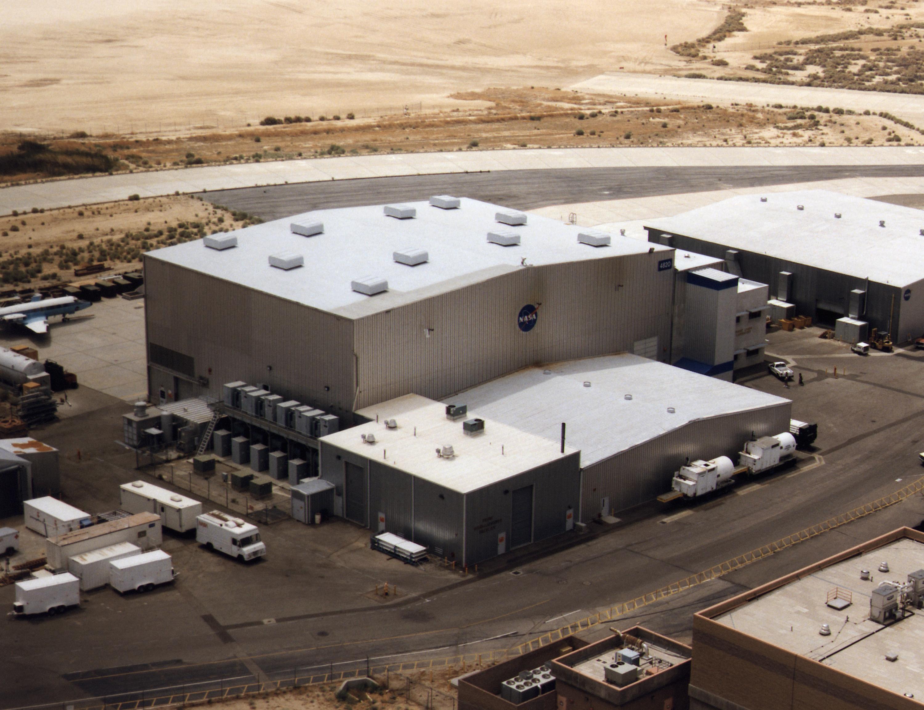
The FLL consists of a large, high-bay test area with adjacent laboratories, offices and storage. The laboratory’s 164 x 120-foot reinforced concrete floor contains tie-down slots to anchor test setups and is accessed from the entry ramp by a 136 x 40-foot door.
The open area for testing is approximately 146 x 113 feet. A five-ton rail crane with a maximum hook height of 39 feet services the entire test-area floor.
The FLL’s data acquisition and test control room is on the second floor overlooking the main test area. Instrumentation and electronic-support laboratories are also available. Additional laboratory features include closed-circuit television for remote monitoring, and a public address and a headset-equipped audio communications system.
Main High Bay
- 164 ft wide x 120 ft deep x 40 ft high
- Load carrying floor tracks throughout
- 5 ton overhead crane
Aircraft Access
- Via 136 ft wide x 40 ft high door
- Direct access via DFRC and EAFB taxiways and runways including Rodgers Dry Lakebed
Mechanical Load
- 80 channels of load control
- 4 channels portable load control system
- 5 ton overhead crane
- Stock of hydraulic rams with various load and stroke capabilities
- Stock of load cells of various capacities up to 300,000 lb tension/compression
Radiant Heating
Quartz radiant lamps:
- 216 temperature control channels
- 20 MW electrical power available
- Temperatures up to ~2,500°F
- In-stock or custom built reflectors depending on application
Graphite radiant heating elements:
- 48 temperature control channels
- Temperatures >3000° F
- May be used in combination with quartz lamp capability
Structural Dynamics Testing (modal survey, structural mode interaction)
- 3 point soft support system capable of up to 60,000 lb vehicle weight to simulate flight-like boundary conditions
- Stock of electro-mechanical shakers up to ±50 lbf each
- Stock of accelerometers (up to 900° F service temperature)
Tension/Compression Load Frames
- 10,000 lb (with inert/vacuum environment heating capability to 3000° F)
- 25,000 lb
- 100,000 lb
- 200,000 lb
Diagnostic Capabilities
- Infra-red Thermography
- Accoustic Emission sensor system
- Photogrammetry (spatial deformation and strain mapping)
Instrumentation
- Deflection measurements
- Load Cells
- Foil and fiber-optic strain gage installation (high temperature installation with plasma and Rokide thermal spraying systems)
- Thermocouples and Optical Fiber Thermometry
Data Acquisition
1920+ channels for electrical based sensors
- strain gages, deflection potentiometers, LVDT’s, pressure transducers, etc.)
- up to 240 hz sampling rate per sensor
30 fibers of Fiber Bragg Grating fiber-optic strain measurements
- 14,400 sensors @ up to 42 hz per sensor
38 channels high temperature (1850° F) EFPI fiber-optic strain measurements
- up to 67 hz per channel
Miscellaneous Test Systems
- Blackbody calibration furnace for calibration of optical fiber thermometers, pyrometers, and heat flux gages.
- Strain and temperature sensor characterization systems up to 3000° F
- 4000 gallon Liquid Nitrogen storage and delivery for purge gas generation and direct LN2 use in tests
- Small (4′ x 4′ x 4′) and large (20′ x 24′ x 20′) chambers for inert atmosphere thermal-structural testing
- Ovens for small article thermal tests up to 3000° F
- Test Audio & Video networks
- Secure, Web-based real-time transmission of test data and video with 2-way audio via telephone link
Flight Research Facilities
Flight Demonstrations and Capabilities Project