


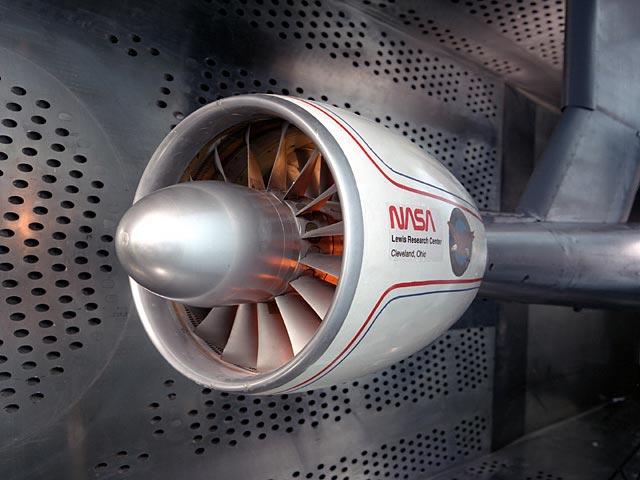
The 8- by 6-Foot Supersonic Wind Tunnel (8×6) operates either in an aerodynamic closed-loop cycle, testing aerodynamic performance models, or in a propulsion open-loop cycle that tests live fuel-burning engines and models.
Facility Overview
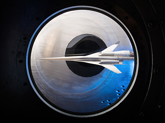
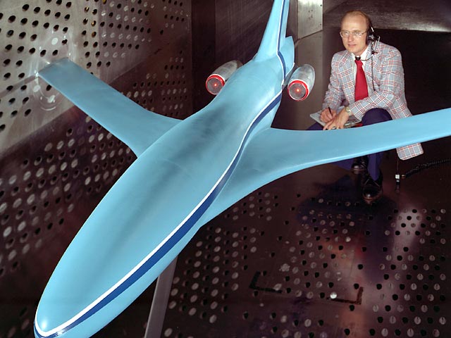
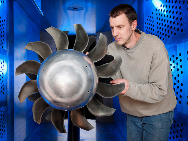
The 8×6 is a world-class facility that provides researchers with the opportunity to explore higher speed regions of flight. It is NASA’s only transonic propulsion wind tunnel. Actively involved in research testing for over 65 years, this facility has been used to enhance the nation’s aeronautics program serving industry, academia, and NASA in-house efforts. Aircraft such as the Advanced Turboprop, the National Aerospace Plane, the Advanced Tactical Fighter, the Joint Strike Fighter, and the High-Speed Civil Transport have been tested in this facility.
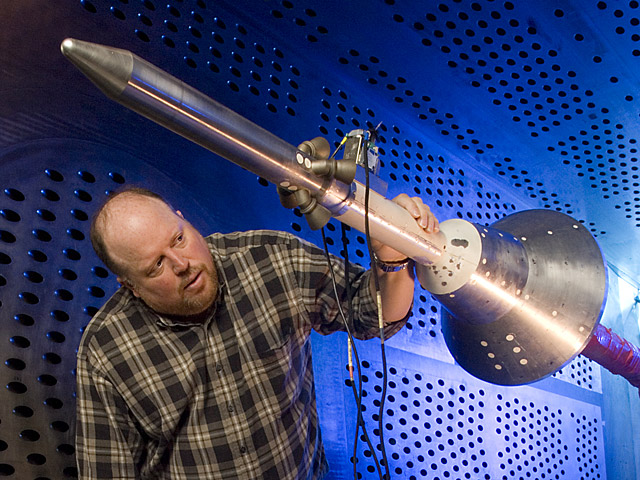
The test section of this facility is 8 feet high by 6 feet wide and 23.5 feet long. The flexible wall nozzle located upstream of the test section is constructed entirely of stainless steel and is used to accelerate the free-stream airflow when its walls are contoured to form a convergent divergent nozzle. To create the pressure required for the airflow to reach speeds up to Mach 2.0, a seven-stage motor-driven compressor located inside the tunnel loop is used. Surrounding the test section walls, a balance chamber is used to provide boundary layer control of the airflow in the test section through perforations in the test section walls. The tunnel can operate at speeds from 0 to Mach 0.1 and from Mach 0.26 to 2.0.
The facility operates either in an aerodynamic closed-loop cycle, testing aerodynamic performance models, or in a propulsion open-loop cycle that tests live fuel burning engines and models. In the propulsion cycle, the tunnel operates by continuously drawing outside air through an air dryer and exhausting it back into the outside environment after it exits an acoustic muffler. This cycle is critical for models that introduce contaminants into the air or use potentially explosive gas mixtures. No exhaust scoop is required in this cycle.
To maximize data quality and minimize operational costs, the facility is controlled and monitored by a digital distributed control system. Steady-state data is collected from model instrumentation, processed, and displayed real-time in engineering and graphical formats at an update rate of once-per-second. Transient data with sampling rates of 2 MHz/sec and an optical instrumentation suite of capabilities are available. To increase test productivity, a test matrix sequencer automatically changes model variables by using a pre-programmed test matrix. Real-time transfer and display of all test data and information can be provided to customer locations outside of NASA Glenn.

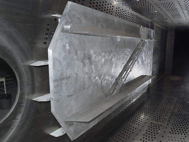
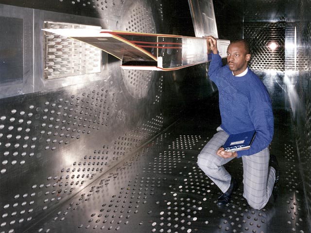
Model supports available in the facility include a ceiling and floor strut for both supersonic and transonic test sections and a wall mount for large or half-span models.
Specialized support systems include:
- High-pressure air
- Altitude exhaust
- Cooling water
- Hydraulics
- Schlieren and advanced optical imagery (sheet lasers, pressure-sensitive paint (PSP), and temperature-sensitive paint (TSP))
- Variety of available research test hardware
Quick Facts
The 8×6 is an atmospheric tunnel with perforated stainless steel walls that provide boundary layer control during transonic operations.
Take a virtual tour of our 8×6 Supersonic Wind Tunnel.
| Mach Number | 0 – 0.1 and 0.26 – 2.0 |
| Test Section | 8-feet high by 6-feet wide by 23.5-feet long |
| Reynolds Number | 1.5 – 5.5 x 10⁶/ft |
| Dynamic Pressure | 100 – 1340 psf |
| Stagnation Pressure | 14 – 25 psia |
| Temperature | 520°R – 700°R |
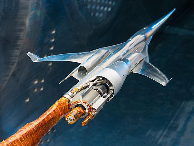
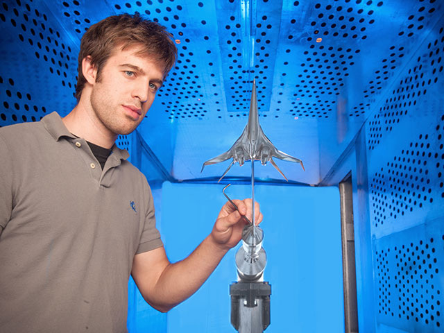
- The 8×6 facility supports research testing of advanced aircraft and launch vehicle concepts.
- Commercial applications include aircraft and missile development, next-generation launch vehicles, and jet or rocket engines.
- The 8×6 is NASA’s only transonic propulsion wind tunnel, operating from Mach 0.26 to 2.0 and at very low speeds from 0 to Mach 0.1.
- When coupled with NASA Glenn’s 10×10 Supersonic Wind Tunnel (10×10), the 8×6 provides aerodynamic and propulsion test capabilities from low-subsonic through high-supersonic Mach range.
- The 8×6 is a world-class test facility that provides researchers the opportunity to explore the subsonic, transonic, and supersonic speed range
Capabilities
The 8×6 provides customers with a facility capable of testing large-scale aero-propulsion hardware:
- In a continuous airstream at Mach numbers from 0 to 0.1 and 0.26 to 2.0
- At varying Reynolds Numbers from 1.5 to 5.5×10⁶/ft and altitude conditions (1,000 to 35,000 ft), depending on Mach number
- Employing high-accuracy data systems to support steady and transient data acquisition
- Supported by a variety of systems including Schlieren, sheet lasers, high-pressure air, and hydraulics
Characteristics and Performance
- Test section size: 8 feet high by 6 feet wide and 23.5 feet long
- Mach number range: 0 to 0.1 and 0.26 to 2.0
- Relative altitude: 1,000 to 35,000 ft
- Reynolds number: 1.5 to 5.5×10⁶/ft
- Stagnation pressure: 14 to 25 psia
- Temperature: 520°R to 700°R
- Dynamic pressure: 100 to 1,340 psf
Tunnel Support Systems
- Combustion air: 38 pps up to 650°F at the heater exit
- Service air: 125 psig
- Combustion air heater: 15 pps at up to 750 °F
- Exhaust: 16-in. line at 20 and 26 in of Hg
- High-pressure air (2600 psig) Storage: 981,000 scf
- Model cooling
Model Support Systems
- Transonic Sting Strut Assembly: Floor mounted with angle of attack range between 0 and 15.0°
- Supersonic Strut: Floor mounted with an angle of attack range between -5 and 20°; axial movement (manual)
- Wall Mount: Typical of half-span models
Model Data and Control System Capabilities
Pressure Systems
The 8×6 electronically scanned pressure system consists of numerous 32 or 64 port miniaturized pressure scanner modules. Multiple measurement ranges are available to accommodate various needs. These can be located outside of the test chamber or within the test article. Each module has a check pressure to ensure correct performance. In-situ calibration is performed via high accuracy standards.
Steady State Data System
COBRA (Collect Observe Broadcast Record and Analyze) is NASA Glenn’s standardized low-speed (under 1,000 samples per second per channel) data system. The system uses commercial-off-the shelf (COTS) hardware and operating systems coupled with specialized data acquisition and application hardware/software modules. It has a flexible and scalable design that uses a distributed network architecture approach. This design allows the attachment of measurement devices from a wide range of vendors. This approach allows the system to evolve over time, permits the latest technology to be used that meets NASA Glenn’s measurement requirements, and provides the environment for the best measurement methods to be applied.
- Universal Data Server
- Runs data processing engine (DPE) that collects, aggregates, and records the data
- Performs engineering unit conversions and complex calculations
- Data distributed to clients in near real time while acquisition and recording continue
- Data Displays
- Run the DataViewer software
- Receive data from COBRA network via the UDS
- Allow user to view real time data in numerical and graphical representations
- Synchronized Time Generator
- Provides Network Time Protocol (NTP), Precision Time Protocol (PTP), and Inter Range Instrumentation Group (IRIG) signals to the data acquisition systems and nodes in the COBRA system
- Synchronized to GPS/USNO via the Glenn central time source
- Reprocessing Data Export Server
- Allows user to reprocess data (correct calculations, add calculations, change coefficients, etc.)
- Exports data to files
- Acquisitions Devices
- Modular and scalable with support for a wide variety of measurement devices:
- Analog Input System
- Electromechanical Scanning Pressure
- Digital Temperature Scanners
- Frequency Inputs
- Digital I/O
- Avionics Interfaces
- Modular and scalable with support for a wide variety of measurement devices:
Dynamic Data System
The dynamic data systems provide muti-channel high-speed digitized acquisition of rapidly changing cyclic or non-periodic impulse type events. The system consists of:
- Programmable filter/amplifying front end
- 24 bit sigma delta ADC with anti-aliasing filter
- Counter channels and math channels also available
- Data transfer in near real time available by request
- Custom displays
- Various sampling rates for differing bandwidth needs.
Flow Visualization
- Pressure sensitive paint
- Conventional Schlerien systems
- Sheet laser
- Oil flow visualization
- High-speed video
Test Article Controls
- Digital model control system with graphical interface
- Automated test article sequencing system
Contact
8×6 Supersonic Wind Tunnel (8×6)
Facility Manager: Michelle Lasic
216-433-3996
Michelle.Lasic@nasa.gov
Test Facility Management Branch
Acting Chief: Taylor Varouh
216-433-6347
Taylor.Varouh@nasa.gov
Using Our Facilities
NASA’s Glenn Research Center in Cleveland provides ground test facilities to industry, government, and academia. If you are considering testing in one of our facilities or would like further information about a specific facility or capability, please let us know.
Gallery


/Hubble%20Space%20Telescope%20(A).png)