


.png?w=1024)


What is a wind tunnel?
If you’ve ever flown on a plane, you’ve probably been in a vehicle that NASA helped develop. Because before something can fly in the sky, it needs to “fly” on the ground – and for that you need a wind tunnel. Several of these often huge and essential facilities are found at NASA’s Ames Research Center in California’s Silicon Valley – including the biggest (two!) in the world.
A wind tunnel works by moving air past a stationary object, making it seem like the object is flying. The tunnel is essentially a giant tube with air flowing through it, usually moved along by fans. Important studies of aircraft, spacecraft and related components take place in the test section, a narrower part of the tube where the air flows very smoothly over a test object. This is usually a scaled-down model, but can even be a full-size vehicle. During a test, wind tunnel engineers measure how the design responds “in flight,” observing its stability, aerodynamic performance and more.
Wind tunnels are where an aircraft gets its first safety checks, before it takes to the sky. They’re also where aerospace designers can confirm their design elements perform as expected or try out brand new technologies safely.
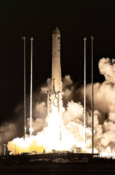
While spacecraft are designed to operate in space, rockets have to travel through the atmosphere to get them there – often the most vulnerable part of the mission. Spacecraft that return to Earth or land on other planets also pass through an atmosphere. NASA tests these in wind tunnels, too.
Today, wind tunnel testing at Ames works hand in hand with sophisticated computer modeling and simulation to help design better, safer aircraft and spacecraft. Computers allow full-scale modeling and evaluation across a broad range of test conditions, while wind tunnels provide more accurate, detailed testing of a smaller set of conditions. They also help confirm the validity of computer models for vehicle shapes and flight conditions that have never been tested before.
Supporting the research of many different teams, the wind tunnels at Ames conduct essential testing for the aerospace and commercial space industries, other government agencies and NASA.
Testing at the Speed of Sound – and Beyond: The Unitary Plan Wind Tunnel
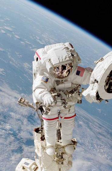
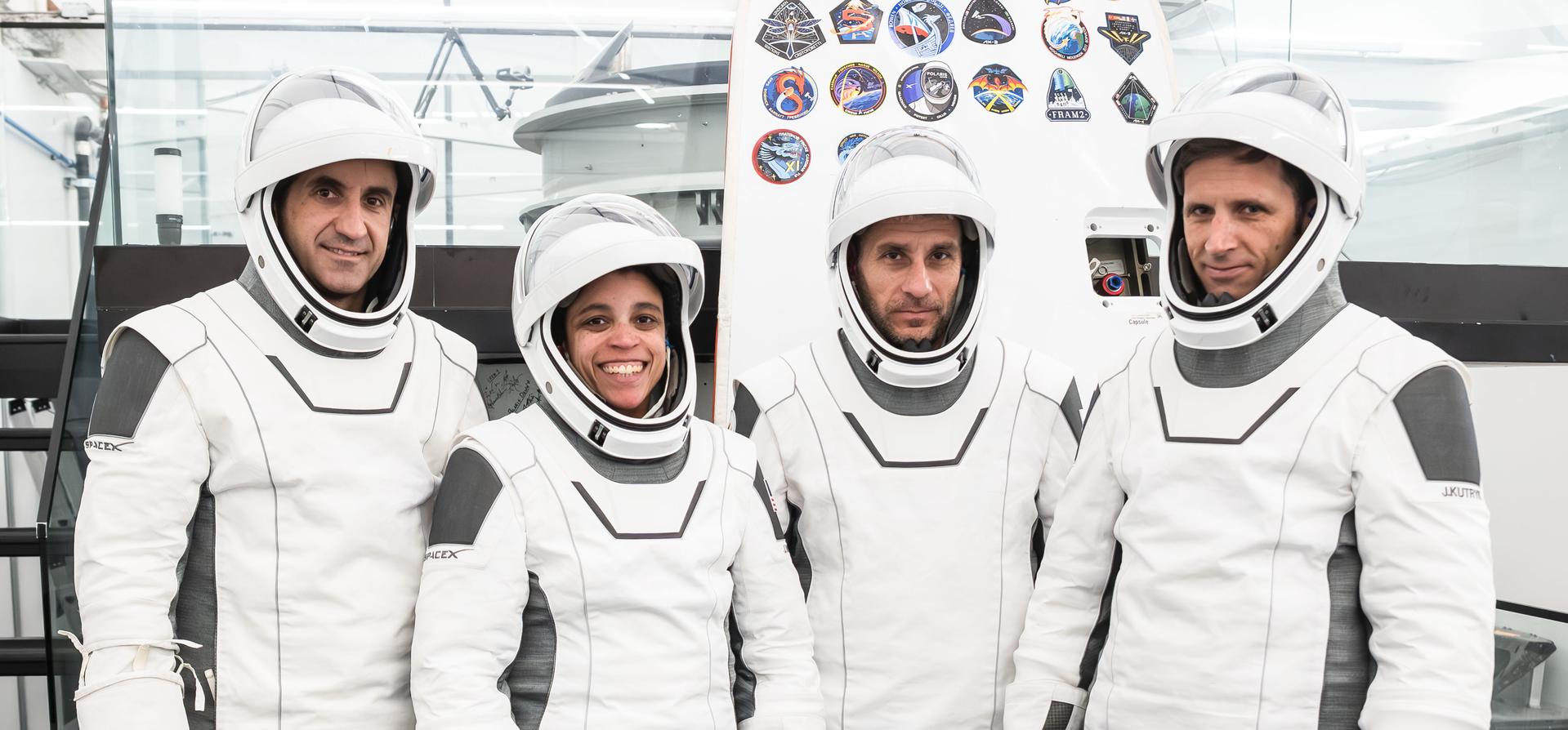
Researchers have tested generations of commercial and military aircraft, as well as NASA space vehicles, at the Unitary Plan Wind Tunnel complex at Ames. Just in the past few years, NASA’s newest X-plane, the quiet, supersonic X-59, and NASA’s next great rocket, the Space Launch System, or SLS, have taken essential steps forward in their design within these tunnel walls. The UPWT team recently used their years of experience testing the agency’s Orion capsule to help SpaceX design and run tests of their Crew Dragon. This spacecraft is sending American astronauts to the International Space Station from American soil as part of NASA’s Commercial Crew Program.
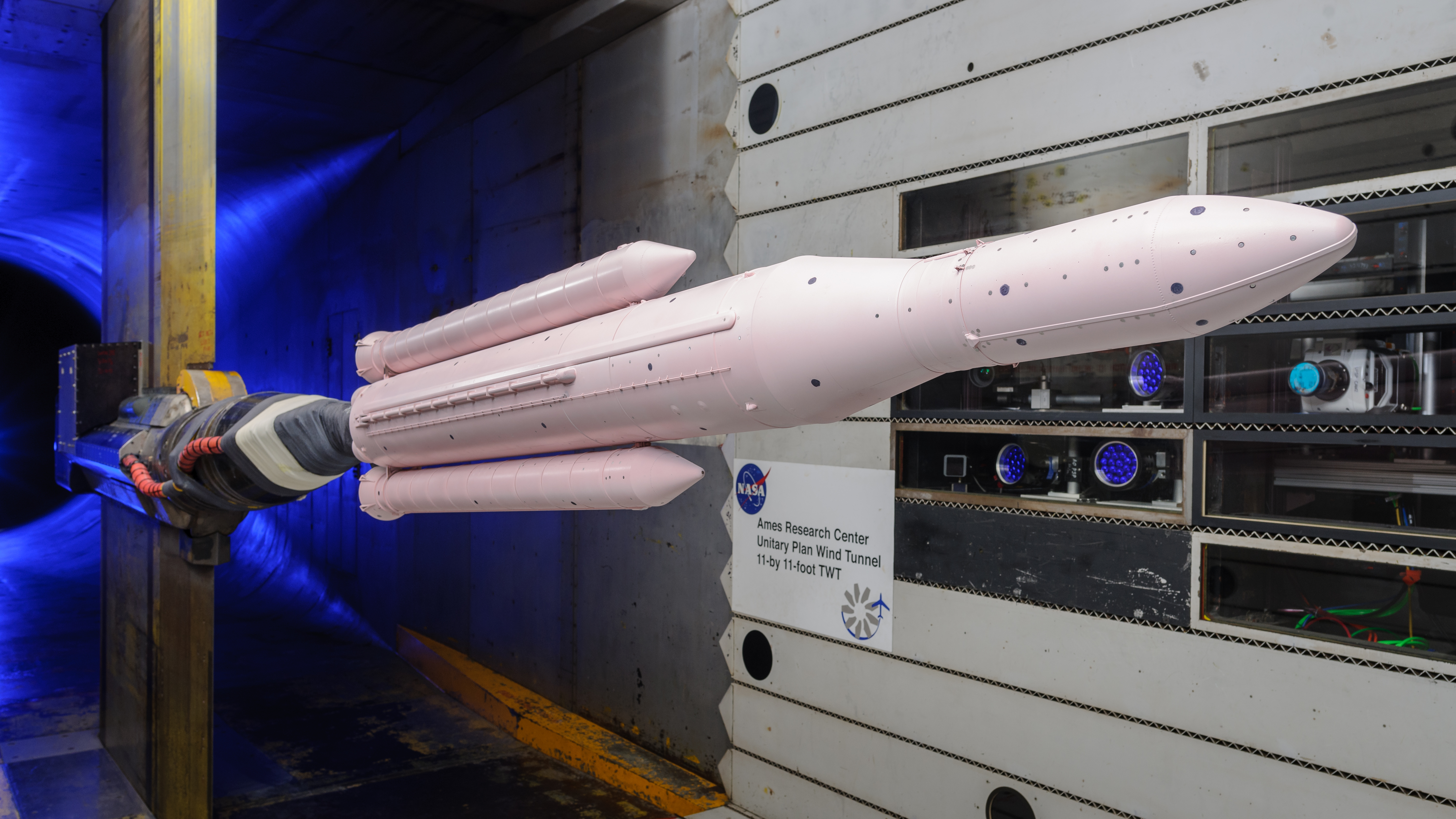
Flight can be simulated at different speeds in the UPWT’s two test sections: at or near the speed of sound in the 11- by 11-foot transonic wind tunnel and at higher velocities – up to about 2.5 times the speed of sound – in the 9- by 7-foot supersonic tunnel.
Before a test, team members spend two weeks in model preparation rooms, installing and checking instruments onboard the high-fidelity model being tested. For the SLS models, there were hundreds of these, from tiny pressure sensors embedded in the model surface to large systems of strain gauges that measure aerodynamic forces. Once ready for testing, a model is mounted on a support strut inside the test section of the tunnel. This lets air flow freely along the test object and allows its orientation to be adjusted to simulate different phases of flight.
Once the fans are turned on to begin testing, conditions like speed and pressure of the airflow can be controlled. Large, specialized windows installed in the tunnel side walls, ceiling and floor let researchers capture images used to visualize the air flow around the model. One advanced imaging technique used in the UPWT relies on a hot pink, pressure-sensitive paint to measure the constantly changing pressure forces of flight on aircraft and spacecraft designs.
For researchers:
- Ames Unitary Plan Wind Tunnel website
- Details of the 11- by 11-foot transonic test section
- Details of the 9- by 7-foot supersonic test section
Home to the World’s Largest Wind Tunnels: The National Full-Scale Aerodynamics Complex
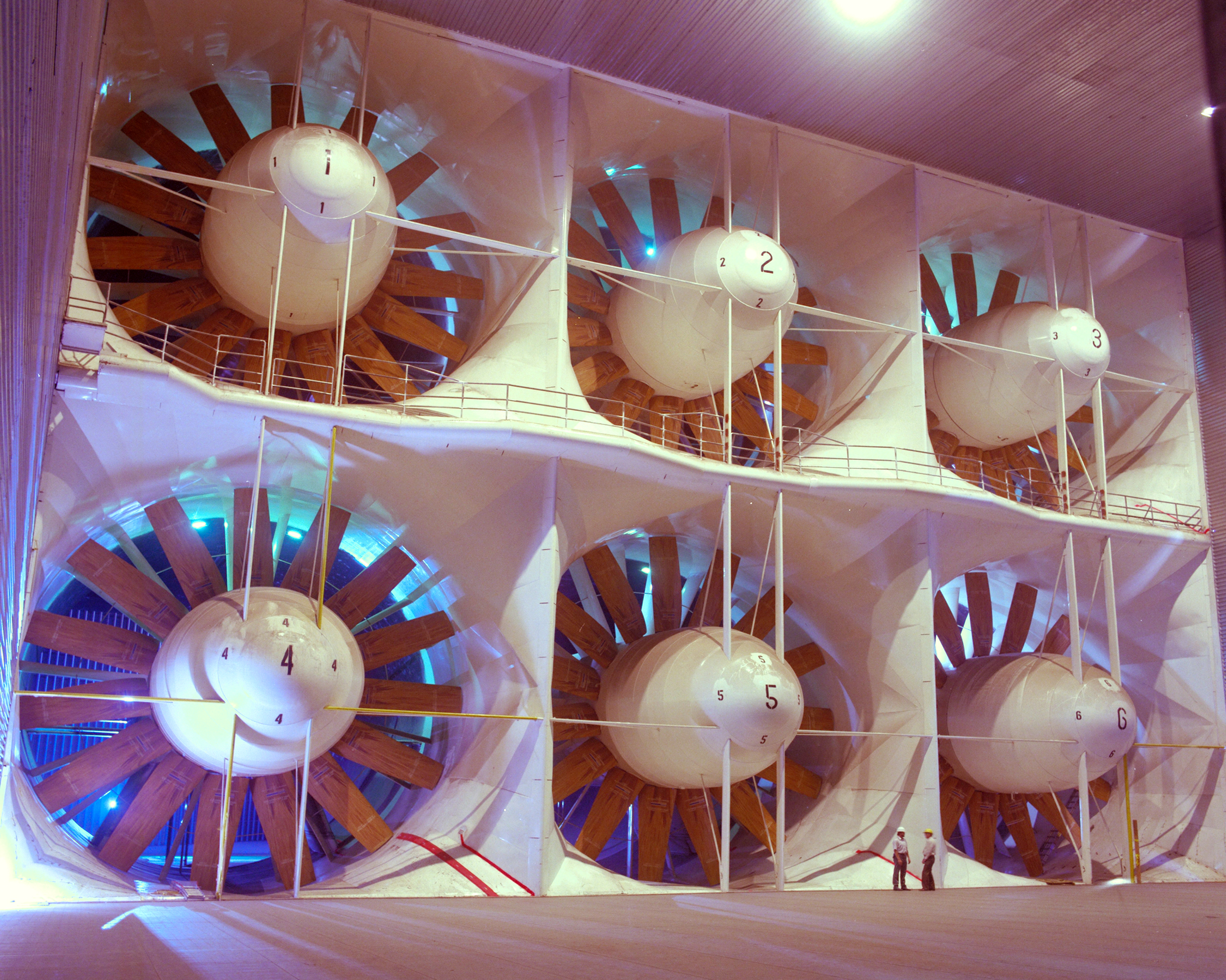
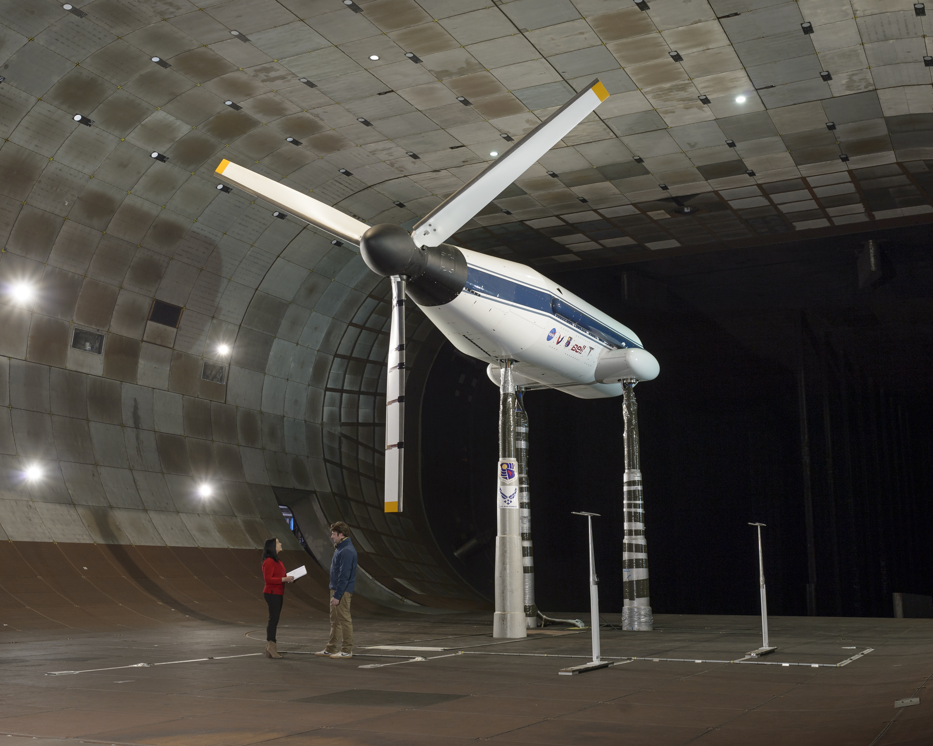
As the name suggests, the National Full-Scale Aerodynamics Complex is used to determine basic aerodynamic characteristics of full-scale and large-scale air vehicles and more. It is made up of the two largest wind tunnels in the world, with test sections of 40 by 80 feet and 80 by 120 feet. Currently managed and operated by the U.S. Air Force, they provide vital wind testing for some of the nation’s most sophisticated commercial and military aircraft, spacecraft, wind turbines, trucks and even the huge parachutes used to safely land NASA rovers on Mars.
The air intake for the NFAC is the size of a football field standing on its edge. Air drawn from outdoors passes through the cavernous 80- by 120-foot test section – big enough to accommodate a full-scale Boeing 737 airplane – at a maximum speed of 115 miles per hour. It moves through the smaller section at speeds up to 345 miles per hour. Airflow is driven by six enormous fans each 40 feet in diameter, and each with a 22,500-horsepower electric motor.
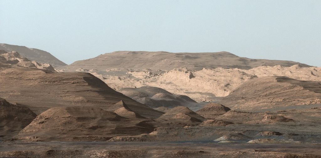
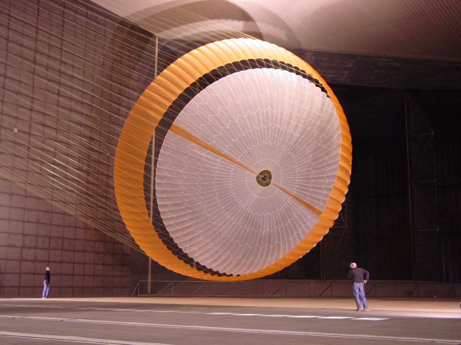
The huge capacity of the NFAC wind tunnels was necessary to test the parachute that helped land NASA’s Mars Science Laboratory, including the Curiosity rover, on Mars. The parachute measured more than 165 feet in length and opened to a diameter of nearly 51 feet. Low-speed inflation of the parachute on Earth simulated the forces the system would need to withstand entering the less-dense Martian atmosphere. Prior to full-scale testing at the NFAC, a rigid scale model of the parachute was also tested in the Unitary Plan Wind Tunnel at supersonic speeds.
More recently, NASA’s Tiltrotor Test Rig was tested at the NFAC. The TTR is a complex test bed developed by NASA to study advanced designs for rotor blades – like the blades that helicopters use to fly – up to around 50 feet in diameter. The TTR lets teams observe rotor behavior as an aircraft transitions from vertical takeoff to forward flight. Tiltrotors, the type of aircraft capable of such flight, will be an essential component for some of the craft used as air taxis in the future of Advanced Air Mobility.
For researchers:
- U.S. Air Force fact sheet: National Full-Scale Aerodynamics Complex
For news media:
Members of the news media interested in covering this topic should reach out to the NASA Ames newsroom.