


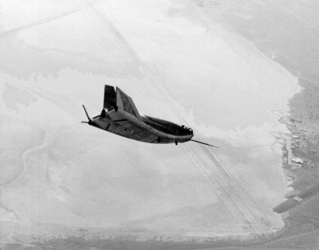
The HL-10 was one of five heavyweight lifting-body designs flown at NASA’s Armstrong Flight Research Center in Edwards, California, from July 1966 to November 1975 to study and validate the concept of safely maneuvering and landing a low lift-over-drag vehicle designed for reentry from space.
Northrop Corporation built the HL-10 and M2-F2, the first two of the fleet of “heavy” lifting bodies flown by NASA Armstrong. The contract for construction of the HL-10 and the M2-F2 was $1.8 million. HL (horizontal landing)-10 (tenth design) was studied by engineers at NASA’s Langley Research Center in Hampton, Virginia.
After delivery to NASA in January 1966, the HL-10 made its first flight on Dec. 22, 1966, with research pilot Bruce Peterson in the cockpit. Although an XLR11 rocket engine was installed in the vehicle, the first 11 drop flights from the B-52 launch aircraft were powerless glide flights to assess handling qualities, stability, and control. In the end, the HL-10 was judged to be the best handling of the three original heavy-weight lifting bodies (M2-F2/F3, HL-10, and X-24A).

The HL-10 was flown 37 times during the lifting body research program and logged the highest altitude and fastest speed in the Lifting Body program. On Feb. 18, 1970, Air Force test pilot Peter Hoag piloted the HL-10 to Mach 1.86 (1,228 mph). Nine days later, NASA pilot Bill Dana flew the vehicle to 90,030 feet, the highest altitude reached in the program.
Some new and different lessons were learned through the successful flight testing of the HL-10. These lessons, when combined with information from it’s sister ship, the M2-F2/F3, provided one option for designers of future atmospheric re-entry vehicles.
Specifications
- Dimensions: Length, 21 ft. 2 in.Width, 13 ft. 7 in.Weight, including pilot, 6,060 lbs.
- Controls: Elevons between vertical and center fins for pitch and roll control. Split rudder on center fin for yaw and speed control. All surfaces used in three-axis stabilizer-augmenter system.
- Power: One XLR11 four-chamber rocket engine fueled by ethyl alcohol and liquid oxygen, producing a rated thrust of of 6,000 lbs.; built by Reaction Motors, Inc.-
- Aux. Power: Silver zinc batteries provided electrical power for control system, flight instruments, radios, cockpit heat, and stability augmentation system. To assist in pre-landing flare, two throttleable hydrogen peroxide rockets provided up to 400 lbs of thrust.
- Landing Gear: Main gear was modified T-38 system retracted manually, and lowered by nitrogen pressure. Nose gear was modified T-39 nose gear, retracted manually and lowered with nitrogen pressure.
- Ejection System: Modified T-37 system.