


Have your pencils and notebooks handy because school is in session. Welcome to Boosters 101.
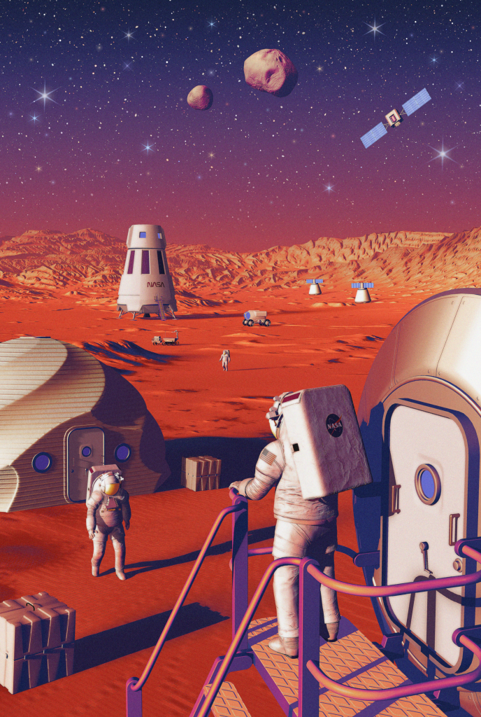
No, this lesson is not about a child seat or an amusement park ride if you looked up boosters in the encyclopedia. This is about rocket boosters — and not only that, but the largest, most powerful ones ever built that will give the “lift” necessary to send astronauts to an asteroid and to Mars on NASA’s new rocket, the Space Launch System (SLS).
Booster Basics
Twin solid rocket boosters were first introduced for human spaceflight missions on the first launch of the space shuttle April 12, 1981. They operate in parallel with the main engines for the first two minutes of flight to provide the thrust needed for the launch vehicle to escape the gravitational pull of Earth. While the shuttle booster used a four-segment solid rocket motor, SLS will use a five-segment motor for more power. The added booster segment contains more solid propellant to allow the rocket to lift more weight and reach a higher altitude before the boosters separate from the core stage.
“To get off the ground, a rocket — especially one with the capabilities that SLS will have — needs a ton of thrust,” said Pat Lampton, technical assistant for solid propulsion at NASA’s Marshall Space Flight Center in Huntsville, Alabama, where the SLS Program is managed for the agency. “You can get that higher amount from a solid propellant.”
The primary components of the SLS booster contain the motor, forward structures and aft structures. These components combine for a total weight of 1.6 million pounds.
Along with propellant, major components of a motor are:
- Case — The rocket motor case is made of a high-strength metal that contains combustion pressure and transmits thrust forces to the rocket.
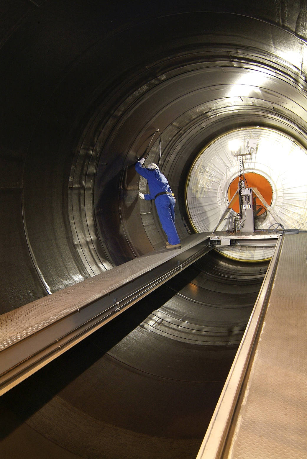
- Nozzle — Controls expansion of chamber pressures and includes the thrust vector control system, which guides and controls the rocket. The nozzle is the most complex part of the booster and is big enough for an average adult to walk through.
- Igniter — A little rocket motor that provides high pressure, high temperature gases to initiate the main propellant materials.
- Insulation — Material that keeps the hardware from melting from extreme temperatures created by the combustion gases.
The forward structures include the nose cone, frustum and forward skirt. The nose cone and frustum protect the rocket from the impact of aerodynamic pressure and heating during ascent. The forward skirt houses booster avionics that work with the SLS avionics to monitor booster conditions and steer the exhaust nozzles. It bears most of the forces carried onto the rocket during flight, and serves as one of two attachment points for the SLS core stage. The core stage, towering more than 200 feet tall with a diameter of 27.6 feet, will store cryogenic liquid hydrogen and liquid oxygen that will feed the vehicle’s RS-25 engines.
The aft structure is composed of the aft skirt and thrust vector control system. The aft skirt has to support the entire weight of the SLS vehicle on the launch vehicle on the launch pad and contains the thrust vector control system that steers the rocket nozzle based on commands from the booster avionics.
When completed, each SLS booster will be approximately 177 feet long — taller than the Statue of Liberty from base to torch. They will be 12 feet in diameter, weigh 801 tons and produce 3.6 million pounds of thrust. SLS will use two, five-segment boosters. The motor is designed to burn for 126 seconds. During that time, it produces more than 75 percent of the total SLS thrust.
How It’s Made
The propellant is a mix of aluminum fuel, oxidizers and other materials that combust to convert stored chemical energy into high pressure/high temperatures to provide the thrust to the booster. “Aluminum loves to burn when it gets hot,” Lampton said. At SLS booster prime contractor Orbital ATK ‘s facilities in Promontory, Utah, a 600-gallon bread mixer is used to blend the propellant materials together before being cured.
When boosters are ignited, temperatures reach more than 5,000 degrees Fahrenheit from the combustion gases, which can melt the hardware. That’s why insulation is needed for each booster segment. The insulation is made of rubber materials found in medical gloves and car window lining and protects the motor case from high-temperature propellant combustion gases. Replacing previously-used asbestos with new insulation materials for SLS will make them more environmentally friendly and safe.
Once each booster segment is insulated and lined, they are filled with about 280,000 pounds of propellant and allowed to solidify. They undergo several rounds of X-ray and ultrasonic inspections before being certified for launch.
Testing
NASA and Orbital ATK have successfully completed three, full-scale development test firings of the five-segment booster. The first SLS qualification test for the booster is scheduled for March 11 at Orbital ATK ‘s test area in Promontory.
The two-minute, full-duration static test is a significant milestone for the program and will support qualification of the booster design for performance at the highest end of the motor’s accepted propellant temperature range.
“Years of extensive work and testing have gone into preparing us for this qualification test,” said Alex Priskos, manager of the SLS Boosters Office at Marshall. “We can’t stress enough what a big deal this is in preparing the rocket for flight.”
Some 103 design objectives will be measured through more than 534 instrumentation channels on the booster. The booster will be heated to 90 degrees Fahrenheit to measure solid rocket booster performance at high temperatures upon ignition, as well as to demonstrate that it meets applicable ballistic requirements.
This test will continue to advance understanding of five-segment solid rocket motor performance and will specifically assess performance at the highest end of the motor’s accepted propellant temperature range. Once qualification is complete, the solid rocket motor will be certified to fly at propellant temperatures ranging between 40-90 degrees Fahrenheit.
Other objectives include data gathering on vital motor upgrades, such as the new insulation and propellant liner and the redesigned nozzle, which increases the robustness of the design.
Once this test and a second, low-temperature test planned for early 2016 are complete, the hardware testing to support qualification will be complete. The boosters will then be ready to proceed toward the first flight of SLS.
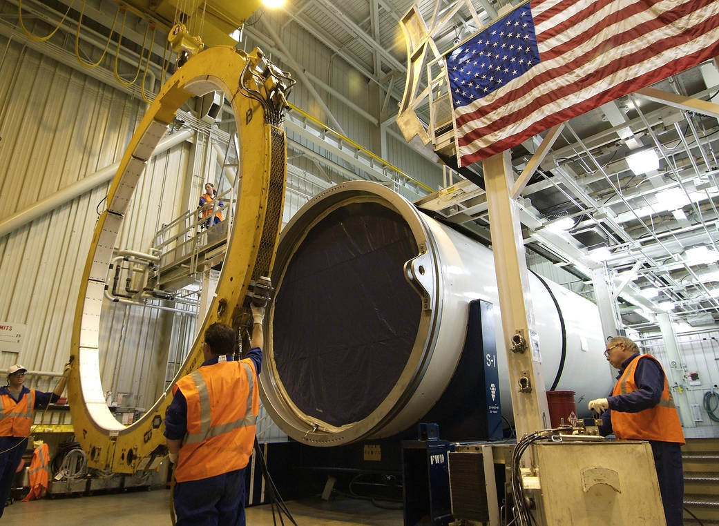
Assembly and Launch
The motor segments will be transported by rail to NASA’s Kennedy Space Center in Florida, where they will join the forward and aft skirt assemblies. Once the boosters are assembled and checked out, they will be mated with the SLS core stage in the Vehicle Assembly Building at Kennedy.
When the rocket is on the pad for launch, NASA control operations personnel will send a signal commanding the thrust vector control startup and nozzle steering checkout. A command from the SLS vehicle flight computers to the booster igniter at the top of each booster starts the burn of the propellant along the entire, inside length of the five-segment motor.
The gasses from combustion are expelled through the nozzle creating thrust. When in flight, the booster burns for approximately 126 seconds before separating from the core stage. Small solid rocket motors push the booster down and away from the SLS as it continues into space. The boosters fall into the Atlantic Ocean and, by design, are expendable.
“We don’t need to recover the boosters because we have saved enough booster hardware to advance them for SLS specifications, resulting in cost savings,” said Bruce Tiller, deputy manager of the SLS Boosters Office at Marshall. “Removing all the parachutes and their associated infrastructure lifts many thousands of pounds off the vehicle and improves performance to carry more payload.”
The first flight test of the SLS will feature a configuration for a 70-metric-ton (77-ton) lift capacity and carry an uncrewed Orion spacecraft beyond low-Earth orbit to test the performance of the integrated system. As the SLS evolves, it will provide an unprecedented lift capability of 130 metric tons (143 tons) to enable missions even farther into our solar system.
For more information on SLS, visit: