


6.1 Technical Planning
6.2 Requirements Management
6.3 Interface Management
6.4 Technical Risk Management
6.5 Configuration Management
6.6 Technical Data Management
6.7 Technical Assessment
6.8 Decision Analysis
The Technical Planning Process, the first of the eight technical management processes contained in the systems engineering engine, establishes a plan for applying and managing each of the common technical processes that will be used to drive the development of system products and associated work products. This process also establishes a plan for identifying and defining the technical effort required to satisfy the project objectives and life cycle phase success criteria within the cost, schedule, and risk constraints of the project.
This effort starts with the technical team conducting extensive planning early in Pre-Phase A. With this early planning, technical team members will understand the roles and responsibilities of each team member, and can establish cost and schedule goals and objectives. From this effort, the Systems Engineering Management Plan (SEMP) and other technical plans are developed and baselined. Once the SEMP and technical plans have been established, they should be synchronized with the project master plans and schedule. In addition, the plans for establishing and executing all technical contracting efforts are identified.
Crosscutting Technical Management Keys
- Thoroughly understand and plan the scope of the technical effort by investing time upfront to develop the technical product breakdown structure, the technical schedule and workflow diagrams, and the technical resource requirements and constraints (funding, budget, facilities, and long-lead items) that will be the technical planning infrastructure. The systems engineer also needs to be familiar with the non-technical aspects of the project.
- Define all interfaces and assign interface authorities and responsibilities to each, both intra-and inter-organizational. This includes understanding potential incompatibilities and defining the transition processes.
- Control of the configuration is critical to understanding how changes will impact the system. For example, changes in design and environment could invalidate previous analysis results.
- Conduct milestone reviews to enable a critical and valuable assessment to be performed. These reviews are not to be solely used to meet contractual or scheduling incentives. These reviews have specific entrance criteria and should be conducted when these are met.
- Understand any biases, assumptions, and constraints that impact the analysis results.
- Place all analysis under configuration control to be able to track the impact of changes and understand when the analysis needs to be reevaluated.
This is a recursive and iterative process. Early in the life cycle, the technical plans are established and synchronized to run the design and realization processes. As the system matures and progresses through the life cycle, these plans should be updated as necessary to reflect the current environment and resources and to control the project’s performance, cost, and schedule. At a minimum, these updates will occur at every Key Decision Point (KDP). However, if there is a significant change in the project, such as new stakeholder expectations, resource adjustments, or other constraints, all plans should be analyzed for the impact of these changes on the baselined project.
6.1.1 Process Description
Figure 6.1-1 provides a typical flow diagram for the Technical Planning Process and identifies typical inputs, outputs, and activities to consider in addressing technical planning.
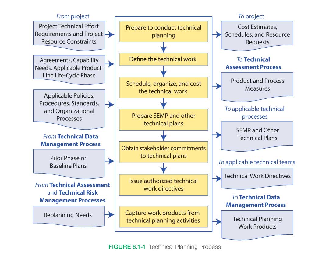
6.1.1.1 Inputs
Input to the Technical Planning Process comes from both the project management and technical teams as outputs from the other common technical processes. Initial planning utilizing external inputs from the project to determine the general scope and framework of the technical effort will be based on known technical and programmatic requirements, constraints, policies, and processes. Throughout the project’s life cycle, the technical team continually incorporates results into the technical planning strategy and documentation and any internal changes based on decisions and assessments generated by the other processes of the SE engine or from requirements and constraints mandated by the project.
- Project Technical Effort Requirements and Project Resource Constraints: The program/project plan provides the project’s top-level technical requirements, the available budget allocated to the program/project from the program, and the desired schedule to support overall program needs. Although the budget and schedule allocated to the program/project serve as constraints, the technical team generates a technical cost estimate and schedule based on the actual work required to satisfy the technical requirements. Discrepancies between the allocated budget and schedule and the technical team’s actual cost estimate and schedule should be reconciled continuously throughout the life cycle.
- Agreements, Capability Needs, Applicable Product Life Cycle Phase: The program/project plan also defines the applicable life cycle phases and milestones, as well as any internal and external agreements or capability needs required for successful execution. The life cycle phases and programmatic milestones provide the general framework for establishing the technical planning effort and for generating the detailed technical activities and products required to meet the overall milestones in each of the life cycle phases.
- Applicable Policies, Procedures, Standards, and Organizational Processes: The program/project plan includes all programmatic policies, procedures, standards, and organizational processes that should be adhered to during execution of the technical effort. The technical team should develop a technical approach that ensures the program/project requirements are satisfied and that any technical procedures, processes, and standards to be used in developing the intermediate and final products comply with the policies and processes mandated in the program/project plan.
- Prior Phase or Baseline Plans: The latest technical plans (either baselined or from the previous life cycle phase) from the Data Management or Configuration Management Processes should be used in updating the technical planning for the upcoming life cycle phase.
- Replanning Needs: Technical planning updates may be required based on results from technical reviews conducted in the Technical Assessment Process, issues identified during the Technical Risk Management Process, or from decisions made during the Decision Analysis Process.
6.1.1.2 Process Activities
Technical planning as it relates to systems engineering at NASA is intended to define how the project will be organized, structured, and conducted and to identify, define, and plan how the 17 common technical processes in NPR 7123.1, NASA Systems Engineering Processes and Requirements will be applied in each life cycle phase for all levels of the product hierarchy (see Section 6.1.2.1 in the NASA Expanded Guidance for Systems Engineering at https://nen.nasa.gov/web/se/doc-repository.) within the system structure to meet product life cycle phase success criteria. A key document capturing and updating the details from the technical planning process is the SEMP.
The SEMP is a subordinate document to the project plan. The project plan defines how the project will be managed to achieve its goals and objectives within defined programmatic constraints. The SEMP defines for all project participants how the project will be technically managed within the constraints established by the project. The SEMP also communicates how the systems engineering management techniques will be applied throughout all phases of the project life cycle.
Technical planning should be tightly integrated with the Technical Risk Management Process (see Section 6.4) and the Technical Assessment Process (see Section 6.7) to ensure corrective action for future activities will be incorporated based on current issues identified within the project.
Technical planning, as opposed to program or project planning, addresses the scope of the technical effort required to develop the system products. While the project manager concentrates on managing the overall project life cycle, the technical team, led by the systems engineer, concentrates on managing the technical aspects of the project. The technical team identifies, defines, and develops plans for performing decomposition, definition, integration, verification, and validation of the system while orchestrating and incorporating the appropriate concurrent and crosscutting engineering. Additional planning includes defining and planning for the appropriate technical reviews, audits, assessments, and status reports and determining crosscutting engineering discipline and/or design verification requirements.
This section describes how to perform the activities contained in the Technical Planning Process shown in Figure 6.1-1. The initial technical planning at the beginning of the project establishes the technical team members; their roles and responsibilities; and the tools, processes, and resources that will be utilized in executing the technical effort. In addition, the expected activities that the technical team will perform and the products it will produce are identified, defined, and scheduled. Technical planning continues to evolve as actual data from completed tasks are received and details of near-term and future activities are known.
6.1.1.2.1 Technical Planning Preparation
For technical planning to be conducted properly, the processes and procedures that are needed to conduct technical planning should be identified, defined, and communicated. As participants are identified, their roles and responsibilities and any training and/or certification activities should be clearly defined and communicated.
Team Selection
Teams engaged in the early part of the technical planning process need to identify the required skill mix for technical teams that will develop and produce a product. Typically, a technical team consists of a mix of both subsystem and discipline engineers. Considering a spacecraft example, subsystem engineers normally have cognizance over development of a particular subsystem (e.g., mechanical, power, etc.), whereas discipline engineers normally provide specific analyses (e.g., flight dynamics, radiation, etc.). The availability of appropriately skilled personnel also needs to be considered.
To an extent, determining the skill mix required for developing any particular product is a subjective process. Due to this, the skill mix is normally determined in consultation with people experienced in leading design teams for a particular mission or technical application. Some of the subjective considerations involved include the product and its requirements, the mission class, and the project phase.
Continuing with a spacecraft example, most teams typically share a common core of required skills, such as subsystem engineering for mechanical, thermal, power, etc. However, the particular requirements of a spacecraft and mission can cause the skill mix to vary. For example, as opposed to robotic space missions, human-rated systems typically add the need for human systems discipline engineering and environmental control and life support subsystem engineering. As opposed to near Earth space missions, deep space missions may add the need for safety and planetary protection discipline engineering specific to contamination of the Earth or remote solar system bodies. And, as opposed to teams designing spacecraft instruments that operate at moderate temperatures, teams designing spacecraft instruments that operate at cryogenic temperatures will need cryogenics subsystem support.
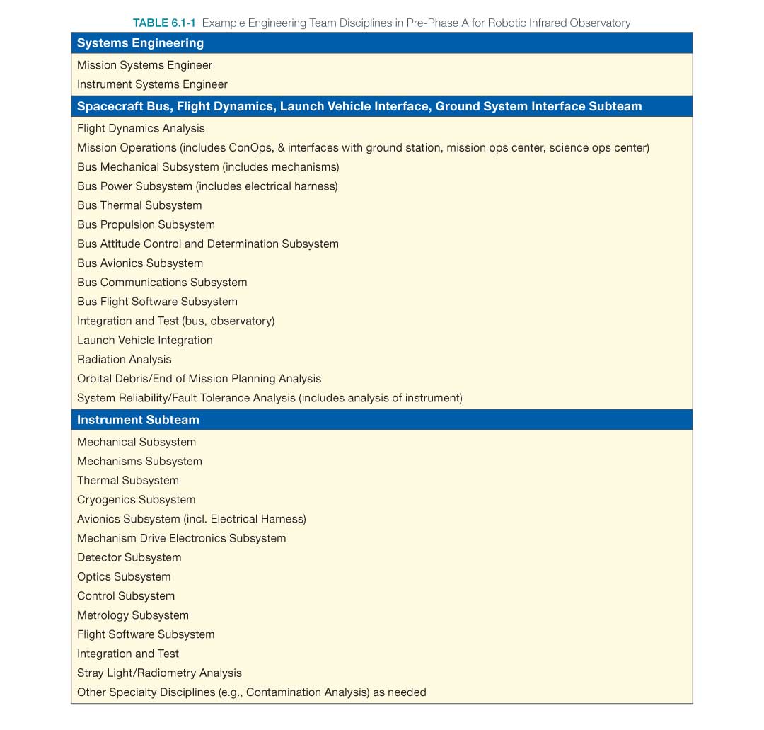
Mission class and project phase may also influence the required team skill mix. For example, with respect to mission class, certain discipline analyses needed for Class A and B missions may not be required for Class D (or lower) missions. And with respect to project phase, some design and analyses may be performed by a single general discipline in Pre-Phase A and Phase A, whereas the need to conduct design and analyses in more detail in Phases B and C may indicate the need for multiple specialized subsystem design and discipline engineering skills.
An example skill mix for a Pre-Phase A technical team tasked to design a cryogenic interferometer space observatory is shown in Table 6.1-1 for purposes of illustration. For simplicity, analysis and technology development is assumed to be included in the subsystem or discipline shown. For example, this means “mechanical subsystem” includes both loads and dynamics analysis and mechanical technology development.
Once the processes, people, and roles and responsibilities are in place, a planning strategy may be formulated for the technical effort. A basic technical planning strategy should address the following:
- The communication strategy within the technical team and for up and out communications;
- Identification and tailoring of NASA procedural requirements that apply to each level of the PBS structure;
- The level of planning documentation required for the SEMP and all other technical planning documents;
- Identifying and collecting input documentation;
- The sequence of technical work to be conducted, including inputs and outputs;
- The deliverable products from the technical work;
- How to capture the work products of technical activities;
- How technical risks will be identified and managed;
- The tools, methods, and training needed to conduct the technical effort;
- The involvement of stakeholders in each facet of the technical effort;
- How the NASA technical team will be involved with the technical efforts of external contractors;
- The entry and success criteria for milestones, such as technical reviews and life cycle phases;
- The identification, definition, and control of internal and external interfaces;
- The identification and incorporation of relevant lessons learned into the technical planning;
- The team’s approach to capturing lessons learned during the project and how those lessons will be recorded;
- The approach for technology development and how the resulting technology will be incorporated into the project;
- The identification and definition of the technical metrics for measuring and tracking progress to the realized product;
- The criteria for make, buy, or reuse decisions and incorporation criteria for Commercial Off-the-Shelf (COTS) software and hardware;
- The plan to identify and mitigate off-nominal performance;
- The “how-tos” for contingency planning and replanning;
- The plan for status assessment and reporting;
- The approach to decision analysis, including materials needed, skills required, and expectations in terms of accuracy; and
- The plan for managing the human element in the technical activities and product.
By addressing these items and others unique to the project, the technical team will have a basis for understanding and defining the scope of the technical effort, including the deliverable products that the overall technical effort will produce, the schedule and key milestones for the project that the technical team should support, and the resources required by the technical team to perform the work.
A key element in defining the technical planning effort is understanding the amount of work associated with performing the identified activities. Once the scope of the technical effort begins to coalesce, the technical team may begin to define specific planning activities and to estimate the amount of effort and resources required to perform each task. Historically, many projects have underestimated the resources required to perform proper planning activities and have been forced into a position of continuous crisis management in order to keep up with changes in the project.
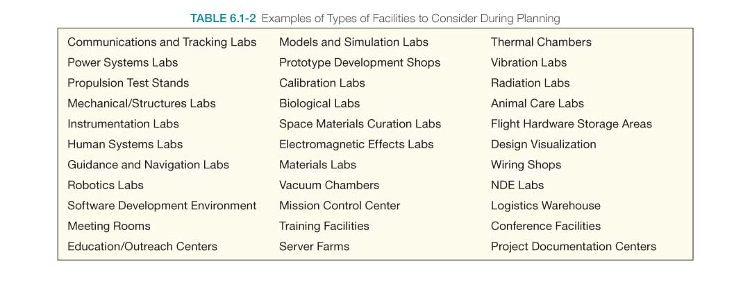
Identifying Facilities
The planning process also includes identifying the required facilities, laboratories, test beds, and instrumentation needed to build, test, launch, and operate a variety of commercial and Government products. A sample list of the kinds of facilities that might be considered when planning is illustrated in Table 6.1-2.
6.1.1.2.2 Define the Technical Work
The technical effort should be defined commensurate with the level of detail needed for the life cycle phase. When performing the technical planning, realistic values for cost, schedule, and labor resources should be used. Whether extrapolated from historical databases or from interactive planning sessions with the project and stakeholders, realistic values should be calculated and provided to the project team. Contingency should be included in any estimate and should be based on the complexity and criticality of the effort. Contingency planning should be conducted. The following are examples of contingency planning:
- Additional, unplanned-for software engineering resources are typically needed during hardware and systems development and testing to aid in troubleshooting errors/anomalies. Frequently, software engineers are called upon to help troubleshoot problems and pinpoint the source of errors in hardware and systems development and testing (e.g., for writing additional test drivers to debug hardware problems). Additional software staff should be planned into the project contingencies to accommodate inevitable component and system debugging and avoid cost and schedule overruns.
- Hardware-In-the-Loop (HWIL) should be accounted for in the technical planning contingencies. HWIL testing is typically accomplished as a debugging exercise where the hardware and software are brought together for the first time in the costly environment of HWIL. If upfront work is not done to understand the messages and errors arising during this test, additional time in the HWIL facility may result in significant cost and schedule impacts. Impacts may be mitigated through upfront planning, such as making appropriate debugging software available to the technical team prior to the test, etc.
- Similarly, Human-In-The-Loop (HITL) evaluations identify contingency operational issues. HITL investigations are particularly critical early in the design process to expose, identify, and cost-effectively correct operational issues—nominal, maintenance, repair, off-nominal, training, etc.—in the required human interactions with the planned design. HITL testing should also be approached as a debugging exercise where hardware, software, and human elements interact and their performance is evaluated. If operational design and/or performance issues are not identified early, the cost of late design changes will be significant.
6.1.1.2.3 Schedule, Organize, and Budget the Technical Effort
Once the technical team has defined the technical work to be done, efforts can focus on producing a schedule and cost estimate for the technical portion of the project. The technical team should organize the technical tasks according to the project WBS in a logical sequence of events, taking into consideration the major project milestones, phasing of available funding, and timing of the availability of supporting resources.
Scheduling
Products described in the WBS are the result of activities that take time to complete. These activities have time precedence relationships among them that may be used to create a network schedule explicitly defining the dependencies of each activity on other activities, the availability of resources, and the receipt of receivables from outside sources. Use of a scheduling tool may facilitate the development and maintenance of the schedule.
Scheduling is an essential component of planning and managing the activities of a project. The process of creating a network schedule provides a standard method for defining and communicating what needs to be done, how long it will take, and how each element of the project WBS might affect other elements. A complete network schedule may be used to calculate how long it will take to complete a project; which activities determine that duration (i.e., critical path activities); and how much spare time (i.e., float) exists for all the other activities of the project.
“Critical path” is the sequence of dependent tasks that determines the longest duration of time needed to complete the project. These tasks drive the schedule and continually change, so they should be updated. The critical path may encompass only one task or a series of interrelated tasks. It is important to identify the critical path and the resources needed to complete the critical tasks along the path if the project is to be completed on time and within its resources. As the project progresses, the critical path will change as the critical tasks are completed or as other tasks are delayed. This evolving critical path with its identified tasks needs to be carefully monitored during the progression of the project.
Network scheduling systems help managers accurately assess the impact of both technical and resource changes on the cost and schedule of a project. Cost and technical problems often show up first as schedule problems. Understanding the project’s schedule is a prerequisite for determining an accurate project budget and for tracking performance and progress. Because network schedules show how each activity affects other activities, they assist in assessing and predicting the consequences of schedule slips or accelerations of an activity on the entire project.
For additional information on scheduling, refer to NASA/SP-2010-3403, NASA Schedule Management Handbook.
Budgeting
Budgeting and resource planning involve establishing a reasonable project baseline budget and the capability to analyze changes to that baseline resulting from technical and/or schedule changes. The project’s WBS, baseline schedule, and budget should be viewed as mutually dependent, reflecting the technical content, time, and cost of meeting the project’s goals and objectives. The budgeting process needs to take into account whether a fixed cost cap or fixed cost profile exists. When no such cap or profile exists, a baseline budget is developed from the WBS and network schedule. This specifically involves combining the project’s workforce and other resource needs with the appropriate workforce rates and other financial and programmatic factors to obtain cost element estimates. These elements of cost include
- direct labor costs,
- overhead costs,
- other direct costs (travel, data processing, etc.),
- subcontract costs,
- material costs,
- equipment costs,
- general and administrative costs,
- cost of money (i.e., interest payments, if applicable),
- fee (if applicable), and
- contingency (Unallocated Future Expenses (UFE)).
For additional information on cost estimating, refer to the NASA Cost Estimating Handbook and NPR 7120.5, NASA Space Flight Program and Project Management Requirements.
6.1.1.2.4 Prepare the SEMP and Other Technical Plans
Systems Engineering Management Plan
The SEMP is the primary, top-level technical management document for the project and is developed early in the Formulation Phase and updated throughout the project life cycle. The SEMP is driven by the type of project, the phase in the project life cycle, and the technical development risks and is written specifically for each project or project element. While the specific content of the SEMP is tailored to the project, the recommended content is discussed in Appendix J. It is important to remember that the main value of the SEMP is in the work that goes into the planning.
The technical team, working under the overall project plan, develops and updates the SEMP as necessary. The technical team works with the project manager to review the content and obtain concurrence. This allows for thorough discussion and coordination of how the proposed technical activities would impact the programmatic, cost, and schedule aspects of the project. The SEMP provides the specifics of the technical effort and describes the technical processes that will be used, how the processes will be applied using appropriate activities, how the project will be organized to accomplish the activities, and the cost and schedule associated with accomplishing the activities.
The physical length of a SEMP is not what is important. This will vary from project to project. The plan needs to be adequate to address the specific technical needs of the project. It is a living document that is updated as often as necessary to incorporate new information as it becomes available and as the project develops through the Implementation Phase. The SEMP should not duplicate other project documents; however, the SEMP should reference and summarize the content of other technical plans.
The systems engineer and project manager should identify additional required technical plans based on the project scope and type. If plans are not included in the SEMP, they should be referenced and coordinated in the development of the SEMP. Other plans, such as system safety, probabilistic risk assessment, and an HSI Plan also need to be planned for and coordinated with the SEMP. If a technical plan is a stand-alone, it should be referenced in the SEMP. Depending on the size and complexity of the project, these may be separate plans or they may be included within the SEMP. Once identified, the plans can be developed, training on these plans established, and the plans implemented. Examples of technical plans in addition to the SEMP are listed in Appendix K.
The SEMP should be developed during pre-formulation. In developing the SEMP, the technical approach to the project’s life cycle is developed. This determines the project’s length and cost. The development of the programmatic and technical management approaches requires that the key project personnel develop an understanding of the work to be performed and the relationships among the various parts of that work. Refer to Sections 6.1.2.1 and 6.1.1.2 on WBSs and network scheduling, respectively. The SEMP then flows into the project plan to ensure the proper allocation of resources including cost, schedule, and personnel.
The SEMP’s development requires contributions from knowledgeable programmatic and technical experts from all areas of the project that can significantly influence the project’s outcome. The involvement of recognized experts is needed to establish a SEMP that is credible to the project manager and to secure the full commitment of the project team.
Role of the SEMP
The SEMP is the rule book that describes to all participants how the project will be technically managed. The NASA technical team on the project should have a SEMP to describe how it will conduct its technical management, and each contractor should have a SEMP to describe how it will manage in accordance with both its contract and NASA’s technical management practices. Since the SEMP is unique to a project and contract, it should be updated for each significant programmatic change or it will become outmoded and unused and the project could slide into an uncontrolled state. The lead NASA field Center should have its SEMP developed before attempting to prepare an initial cost estimate since activities that incur cost, such as technical risk reduction and human element accounting, need to be identified and described beforehand. The contractor should have its SEMP developed during the proposal process (prior to costing and pricing) because the SEMP describes the technical content of the project, the potentially costly risk management activities, and the verification and validation techniques to be used, all of which should be included in the preparation of project cost estimates. The SEMPs from the supporting Centers should be developed along with the primary project SEMP. The project SEMP is the senior technical management document for the project; all other technical plans should comply with it. The SEMP should be comprehensive and describe how a fully integrated engineering effort will be managed and conducted.
Verification Plan
The verification plan is developed as part of the Technical Planning Process and is baselined at PDR. As the design matures throughout the life cycle, the plan is updated and refined as needed. The task of preparing the verification plan includes establishing the method of verification to be performed, dependent on the life cycle phase; the position of the product in the system structure; the form of the product used; and the related costs of verification of individual specified requirements. The verification methods include analyses, inspection, demonstration, and test. In some cases, the complete verification of a given requirement might require more than one method. For example, to verify the performance of a product may require looking at many use cases. This might be accomplished by running a Monte Carlo simulation (analysis) and also running actual tests on a few of the key cases. The verification plan, typically written at a detailed technical level, plays a pivotal role in bottom-up product realization.
Types of Hardware
Breadboard: A low fidelity unit that demonstrates function only without considering form or fit in the case of hardware or platform in the case of software. It often uses commercial and/or ad hoc components and is not intended to provide definitive information regarding operational performance.
Brassboard: A medium fidelity functional unit that typically tries to make use of as much operational hardware/software as possible and begins to address scaling issues associated with the operational system. It does not have the engineering pedigree in all aspects, but is structured to be able to operate in simulated operational environments in order to assess performance of critical functions.
Engineering Unit: A high fidelity unit that demonstrates critical aspects of the engineering processes involved in the development of the operational unit. Engineering test units are intended to closely resemble the final product (hardware/software) to the maximum extent possible and are built and tested so as to establish confidence that the design will function in the expected environments. In some cases, the engineering unit will become the final product, assuming proper traceability has been exercised over the components and hardware handling.
Prototype Unit: The prototype unit demonstrates form, fit, and function at a scale deemed to be representative of the final product operating in its operational environment. A subscale test article provides fidelity sufficient to permit validation of analytical models capable of predicting the behavior of full-scale systems in an operational environment.
Qualification Unit: A unit that is the same as the flight unit (form, fit, function, components, etc.) that will be exposed to the extremes of the environmental criteria (thermal, vibration, etc.). The unit will typically not be flown due to these off-nominal stresses.
Protoflight Unit: In projects that will not develop a qualification unit, the flight unit may be designated as a protoflight unit and a limited version of qualification test ranges will be applied. This unit will be flown.
Flight Unit: The end product that will be flown and will typically undergo acceptance level testing.
Note: The final, official verification of the end product should be on a controlled unit. Typically, attempting to “buy off” a “shall” on a prototype is not acceptable; it is usually completed on a qualification, flight, or other more final, controlled unit.
A phase product can be verified recursively throughout the project life cycle and on a wide variety of product forms. For example:
- simulated (algorithmic models, virtual reality simulator);
- mock-up (plywood, brassboard, breadboard);
- concept description (paper report);
- engineering unit (fully functional but may not be same form/fit);
- prototype (form, fit, and function);
- design verification test units (form, fit, and function is the same, but they may not have flight parts);
- qualification units (identical to flight units but may be subjected to extreme environments); and
- flight units (end product that is flown, including protoflight units).
Verification of the end product—that is, the official “run for the record” verification where the program/project takes credit for meeting a requirement—is usually performed on a qualification, protoflight, or flight unit to ensure its applicability to the flight system. However, with discussion and approval from the program/project and systems engineering teams, verification credit may be taken on lower fidelity units if they can be shown to be sufficiently like the flight units in the areas to be verified.
Any of these types of product forms may be in any of these states:
- produced (built, fabricated, manufactured, or coded);
- reused (modified internal non-developmental products or OTS product); or
- assembled and integrated (a composite of lower-level products).
The conditions and environment under which the product is to be verified should be established and the verification should be planned based on the associated entrance/exit criteria that are identified. The Decision Analysis Process should be used to help finalize the planning details.
Procedures should be prepared to conduct verification based on the method (e.g., analysis, inspection, demonstration, or test) planned. These procedures are typically developed during the design phase of the project life cycle and matured as the design is matured. Operational use scenarios are thought through in order to explore all possible verification activities to be performed.
Note: Verification planning begins early in the project life cycle during the requirements development phase. (See Section 4.2.) The verification approach to use should be included as part of requirements development to plan for future activities, to establish special requirements derived from identified verification-enabling products, and to ensure that the requirements are verifiable. Updates to verification planning continue throughout logical decomposition and design development, especially as design reviews and simulations shed light on items under consideration. (See Section 6.1.)
As appropriate, project risk items are updated based on approved verification strategies that cannot duplicate fully integrated test systems, configurations, and/or target operating environments. Rationales, trade space, optimization results, and implications of the approaches are documented in the new or revised risk statements as well as references to accommodate future design, test, and operational changes to the project baseline.
Validation Plan
The validation plan is one of the work products of the Technical Planning Process and is generated during the Design Solution Process to validate the end product against the baselined stakeholder expectations. This plan can take many forms. The plan describes the total Test and Evaluation (T&E) planning from development of lower-end through higher-end products in the system structure and through operational T&E into production and acceptance. It may combine the verification and validation plans into a single document. (See Appendix I for a sample Verification and Validation Plan outline.)
The methods of validation include test, demonstration, inspection, and analysis. While the name of each method is the same as the name of the methods for verification, the purpose and intent as described above are quite different.
Planning to conduct the product validation is a key first step. The method of validation to be used (e.g., analysis, demonstration, inspection, or test) should be established based on the form of the realized end product, the applicable life cycle phase, cost, schedule, resources available, and location of the system product within the system structure.
An established set or subset of expectations or behaviors to be validated should be identified and the validation plan reviewed (an output of the Technical Planning Process, based on design solution outputs) for any specific procedures, constraints, success criteria, or other validation requirements. The conditions and environment under which the product is to be validated should be established and the validation should be planned based on the relevant life cycle phase and associated success criteria identified. The Decision Analysis Process should be used to help finalize the planning details.
It is important to review the validation plans with relevant stakeholders and to understand the relationship between the context of the validation and the context of use (human involvement). As part of the planning process, validation-enabling products should be identified and scheduling and/or acquisition should be initiated.
Procedures should be prepared to conduct validation based on the method planned; e.g., analysis, inspection, demonstration, or test). These procedures are typically developed during the design phase of the project life cycle and matured as the design is matured. Operational and use-case scenarios are thought through in order to explore all possible validation activities to be performed.
Validation is conducted by the user/operator or by the developer as determined by NASA Center directives or the contract with the developers. Systems-level validation (e.g., customer Test and Evaluation (T&E) and some other types of validation) may be performed by an acquirer testing organization. For those portions of validation performed by the developer, appropriate agreements should be negotiated to ensure that validation proof-of-documentation is delivered with the product.
Regardless of the source (buy, make, reuse, assemble and integrate) and the position in the system structure, all realized end products should be validated to demonstrate/confirm satisfaction of stakeholder expectations. Variations, anomalies, and out-of-compliance conditions, where such have been detected, are documented along with the actions taken to resolve the discrepancies. Validation is typically carried out in the intended operational environment or a relevant environment under simulated or actual operational conditions, not necessarily under the tightly controlled conditions usually employed for the Product Verification Process.
Environments
Relevant Environment: Not all systems, subsystems, and/or components need to be operated in the operational environment in order to satisfactorily address performance margin requirements or stakeholder expectations. Consequently, the relevant environment is the specific subset of the operational environment that is required to demonstrate critical “at risk” aspects of the final product performance in an operational environment.
Operational Environment: The environment in which the final product will be operated. In the case of space flight hardware/software, it is space. In the case of ground-based or airborne systems that are not directed toward space flight, it is the environments defined by the scope of operations. For software, the environment is defined by the operational platform.
Validation of phase products can be performed recursively throughout the project life cycle and on a wide variety of product forms. For example:
- simulated (algorithmic models, virtual reality simulator);
- mock-up (plywood, brassboard, breadboard);
- concept description (paper report);
- engineering unit (functional but may not be same form/fit);
- prototype (product with form, fit, and function);
- design validation test units (form, fit, and function may be the same, but they may not have flight parts);
- qualification unit (identical to flight unit but may be subjected to extreme environments); and
- flight unit (end product that is flown).
Any of these types of product forms may be in any of these states:
- produced (built, fabricated, manufactured, or coded);
- reused (modified internal non-developmental products or off-the-shelf product); or
- assembled and integrated (a composite of lower level products).
Note: The final, official validation of the end product should be for a controlled unit. Typically, attempting final validation against the ConOps on a prototype is not acceptable: it is usually completed on a qualification, flight, or other more final, controlled unit.
For additional information on technical plans, refer to the following appendices of this document and to Section 6.1.1.2.4 of the NASA Expanded Guidance for Systems Engineering at https://nen.nasa.gov/web/se/doc-repository:
- Appendix H Integration Plan Outline
- Appendix I Verification and Validation Plan Outline
- Appendix J SEMP Content Outline
- Appendix K Technical Plans
- Appendix L Interface Requirements Document Outline
- Appendix M CM Plan Outline
- Appendix R HSI Plan Content Outline
- Appendix S Concept of Operations Annotated Outline
Note: In planning for validation, consideration should be given to the extent to which validation testing will be done. In many instances, off-nominal operational scenarios and nominal operational scenarios should be utilized. Off-nominal testing offers insight into a system’s total performance characteristics and often assists in identifying the design issues and human-machine interface, training, and procedural changes required to meet the mission goals and objectives. Off-nominal testing as well as nominal testing should be included when planning for validation.
6.1.1.2.5 Obtain Stakeholder Commitments to Technical Plans
Stakeholder Roles in Project Planning
To obtain commitments to the technical plans from the stakeholders, the technical team should ensure that the appropriate stakeholders, including subject domain experts, have a method to provide inputs and to review the project planning for implementation of stakeholder interests.
During the Formulation Phase, the roles of the stakeholders should be defined in the project plan and the SEMP. Review of these plans and the agreements from the stakeholders to the content of these plans constitutes buy-in from the stakeholders to the technical approach. It is essential to identify the stakeholders and get their concurrence on the technical approach.
Later in the project life cycle, stakeholders may be responsible for delivering products to the project. Initial agreements regarding the responsibilities of the stakeholders are key to ensuring that the project technical team obtains the appropriate deliveries from stakeholders.
Stakeholder Involvement in Defining Requirements
The identification of stakeholders is one of the early steps in the systems engineering process. As the project progresses, stakeholder expectations are flowed down through the Logical Decomposition Process, and specific stakeholders are identified for all of the primary and derived requirements. A critical part of the stakeholders’ involvement is in the definition of the technical requirements. As requirements and the ConOps are developed, the stakeholders will be required to agree to these products. Inadequate stakeholder involvement leads to inadequate requirements and a resultant product that does not meet the stakeholder expectations. Status on relevant stakeholder involvement should be tracked and corrective action taken if stakeholders are not participating as planned.
Stakeholder Agreements
Throughout the project life cycle, communication with the stakeholders and commitments from the stakeholders may be accomplished through the use of agreements. Organizations may use an Internal Task Agreement (ITA), a Memorandum Of Understanding (MOU), or other similar documentation to establish the relationship between the project and the stakeholder. These agreements are also used to document the customer and provider responsibilities for defining products to be delivered. These agreements should establish the Measures of Effectiveness (MOEs) or Measures of Performance (MOPs) that will be used to monitor the progress of activities. Reporting requirements and schedule requirements should be established in these agreements. Preparation of these agreements will ensure that the stakeholders’ roles and responsibilities support the project goals and that the project has a method to address risks and issues as they are identified.
Stakeholder Support for Forums
During development of the project plan and the SEMP, forums are established to facilitate communication and document decisions during the life cycle of the project. These forums include meetings, working groups, decision panels, and control boards. Each of these forums should establish a charter to define the scope and authority of the forum and identify necessary voting or nonvoting participants. Ad hoc members may be identified when the expertise or input of specific stakeholders is needed when specific topics are addressed. It is important to ensure that stakeholders have been identified to support the forum.
6.1.1.2.6 Issue Technical Work Directives
The technical team provides technical work directives to Cost Account Managers (CAMs). This enables the CAMs to prepare detailed plans that are mutually consistent and collectively address all of the work to be performed. These plans include the detailed schedules and budgets for cost accounts that are needed for cost management and EVM.
Issuing technical work directives is an essential activity during Phase B of a project when a detailed planning baseline is required. If this activity is not implemented, then the CAMs are often left with insufficient guidance for detailed planning. The schedules and budgets that are needed for EVM will then be based on assumptions and local interpretations of project-level information. If this is the case, it is highly likely that substantial variances will occur between the baseline plan and the work performed. Providing technical work directives to CAMs produces a more organized technical team. This activity may be repeated when replanning occurs.
This “technical work directives” step produces: (1) planning directives to CAMs that result in (2) a consistent set of cost account plans. Where EVM is called for, it produces (3) an EVM planning baseline, including a Budgeted Cost of Work Scheduled (BCWS).
This activity is not limited to systems engineering. This is a normal part of project planning wherever there is a need for an accurate planning baseline. For additional information on Technical Work Directives, refer to Section 6.1.1.2.6 in the NASA Expanded Guidance for Systems Engineering at https://nen.nasa.gov/web/se/doc-repository.
6.1.1.2.7 Capture Technical Planning Work Products
The work products from the Technical Planning Process should be managed using either the Technical Data Management Process or the Configuration Management Process as required. Some of the more important products of technical planning (i.e., the WBS, the SEMP, and the schedule, etc.) are kept under configuration control and captured using the CM process. The Technical Data Management Process is used to capture trade studies, cost estimates, technical analyses, reports, and other important documents not under formal configuration control. Work products, such as meeting minutes and correspondence (including e-mail) containing decisions or agreements with stakeholders also should be retained and stored in project files for later reference.
6.1.1.3 Outputs
Typical outputs from technical planning activities are:
- Technical work cost estimates, schedules, and resource needs: e.g., funds, workforce, facilities, and equipment (to the project) within the project resources;
- Product and process measures: Those needed to assess progress of the technical effort and the effectiveness of processes (to the Technical Assessment Process);
- SEMP and other technical plans: Technical planning strategy, WBS, SEMP, HSI Plan, V&V Plan, and other technical plans that support implementation of the technical effort (to all processes; applicable plans to technical processes);
- Technical work directives: e.g., work packages or task orders with work authorization (to applicable technical teams); and
- Technical Planning Process work products: Includes products needed to provide reports, records, and non-deliverable outcomes of process activities (to the Technical Data Management Process).
The resulting technical planning strategy constitutes an outline, or rough draft, of the SEMP. This serves as a starting point for the overall Technical Planning Process after initial preparation is complete. When preparations for technical planning are complete, the technical team should have a cost estimate and schedule for the technical planning effort. The budget and schedule to support the defined technical planning effort can then be negotiated with the project manager to resolve any discrepancies between what is needed and what is available. The SEMP baseline needs to be completed. Planning for the update of the SEMP based on programmatic changes needs to be developed and implemented. The SEMP needs to be approved by the appropriate level of authority.
6.1.2 Technical Planning Guidance
Refer to Section 6.1.2 in the NASA Expanded Guidance for Systems Engineering at https://nen.nasa.gov/web/se/doc-repository for additional guidance on:
- Work Breakdown Structure (WBS),
- cost definition and modeling, and
- lessons learned.
Additional information on the WBS can also be found in NASA/SP-2010-3404, NASA Work Breakdown Structure Handbook and on costing in the NASA Cost Estimating Handbook.