


6.1 Technical Planning
6.2 Requirements Management
6.3 Interface Management
6.4 Technical Risk Management
6.5 Configuration Management
6.6 Technical Data Management
6.7 Technical Assessment
6.8 Decision Analysis
Configuration management is a management discipline applied over the product’s life cycle to provide visibility into and to control changes to performance and functional and physical characteristics. Additionally, according to SAE Electronic Industries Alliance (EIA) 649B, improper configuration management may result in incorrect, ineffective, and/or unsafe products being released. Therefore, in order to protect and ensure the integrity of NASA products, NASA has endorsed the implementation of the five configuration management functions and the associated 37 underlying principles defined within SAE/EIA-649-2 Configuration Management Requirements for NASA Enterprises.
Together, these standards address what configuration management activities are to be done, when they are to happen in the product life cycle, and what planning and resources are required. Configuration management is a key systems engineering practice that, when properly implemented, provides visibility of a true representation of a product and attains the product’s integrity by controlling the changes made to the baseline configuration and tracking such changes. Configuration management ensures that the configuration of a product is known and reflected in product information, that any product change is beneficial and is effected without adverse consequences, and that changes are managed.
CM reduces technical risks by ensuring correct product configurations, distinguishes among product versions, ensures consistency between the product and information about the product, and avoids the embarrassment cost of stakeholder dissatisfaction and complaint. In general, NASA adopts the CM principles as defined by SAE/EIA 649B, Configuration Management Standard, in addition to implementation as defined by NASA CM professionals and as approved by NASA management.
When applied to the design, fabrication/assembly, system/subsystem testing, integration, and operational and sustaining activities of complex technology items, CM represents the “backbone” of the enterprise structure. It instills discipline and keeps the product attributes and documentation consistent. CM enables all stakeholders in the technical effort, at any given time in the life of a product, to use identical data for development activities and decision-making. CM principles are applied to keep the documentation consistent with the approved product, and to ensure that the product conforms to the functional and physical requirements of the approved design.
6.5.1 Process Description
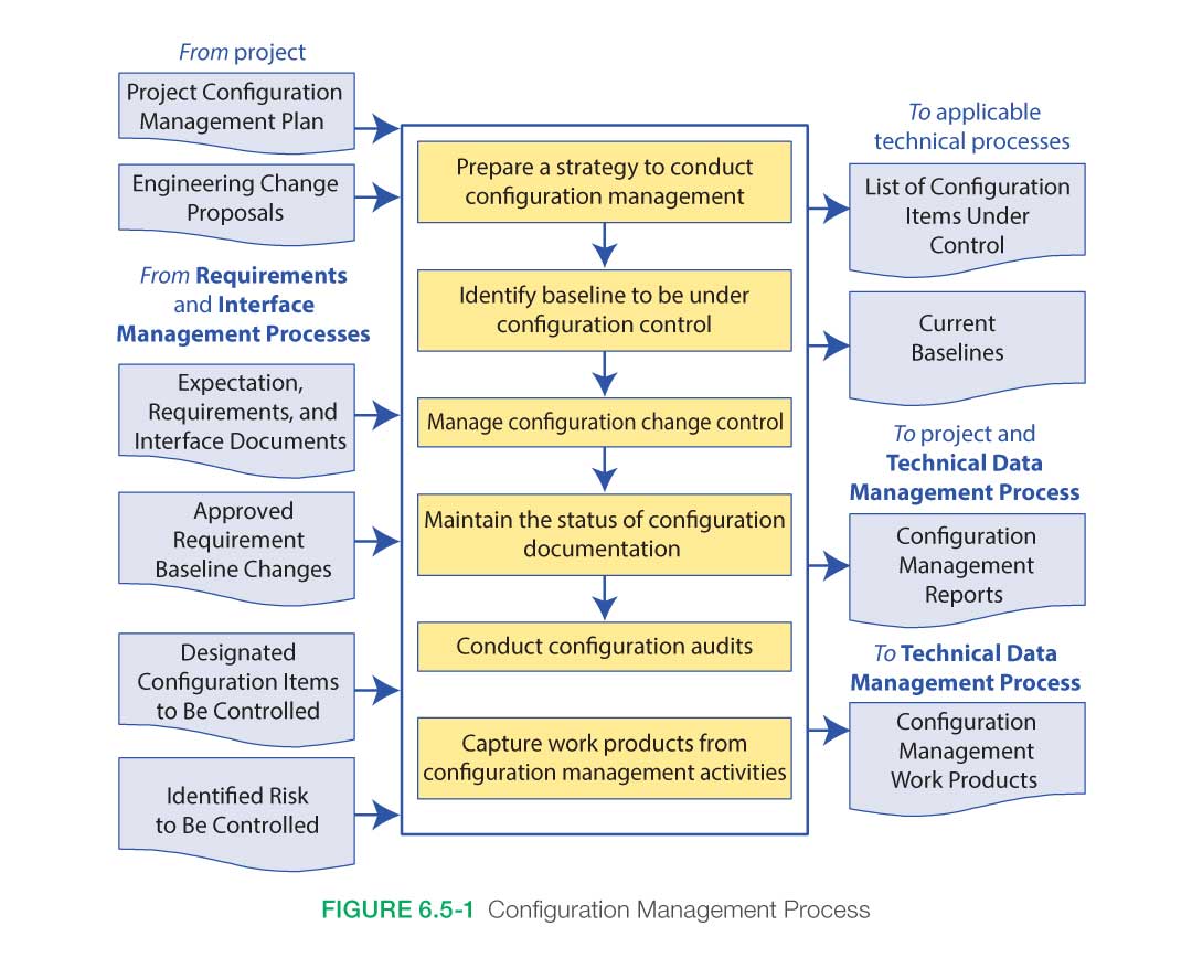
Figure 6.5-1 provides a typical flow diagram for the Configuration Management Process and identifies typical inputs, outputs, and activities to consider in addressing CM.
6.5.1.1 Inputs
The inputs for this process are:
- CM plan: This plan would have been developed under the Technical Planning Process and serves as the overall guidance for this process for the program/project
- Engineering change proposals: These are the requests for changes to the established baselines in whatever form they may appear throughout the life cycle.
- Expectation, requirements and interface documents: These baselined documents or models are key to the design and development of the product.
- Approved requirements baseline changes: The approved requests for changes will authorize the update of the associated baselined document or model.
- Designated configuration items to be controlled: As part of technical planning, a list or philosophy would have been developed that identifies the types of items that will need to be placed under configuration control.
6.5.1.2 Process Activities
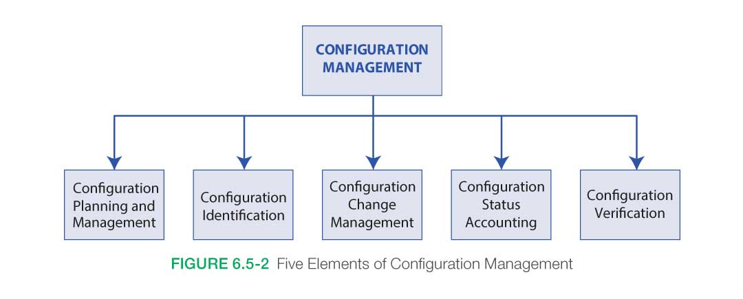
There are five elements of CM (see Figure 6.5-2):
- configuration planning and management
- configuration identification,
- configuration change management,
- Configuration Status Accounting (CSA), and
- configuration verification.
6.5.1.2.1 Prepare a Strategy to Conduct CM
CM planning starts at a program’s or project’s inception. The CM office should carefully weigh the value of prioritizing resources into CM tools or into CM surveillance of the contractors. Reviews by the Center Configuration Management Organization (CMO) are warranted and will cost resources and time, but the correction of systemic CM problems before they erupt into losing configuration control are always preferable to explaining why incorrect or misidentified parts are causing major problems in the program/project.
One of the key inputs to preparing for CM implementation is a strategic plan for the project’s complete CM process. This is typically contained in a CM plan. See Appendix M for an outline of a typical CM plan.
This plan has both internal and external uses:
- Internal: It is used within the program/project office to guide, monitor, and measure the overall CM process. It describes all the CM activities and the schedule for implementing those activities within the program/project.
- External: The CM plan is used to communicate the CM process to the contractors involved in the program/project. It establishes consistent CM processes and working relationships.
The CM plan may be a standalone document or it may be combined with other program/project planning documents. It should describe the criteria for each technical baseline creation, technical approvals, and audits.
6.5.1.2.2 Identify Baseline to be Under Configuration Control
Configuration identification is the systematic process of selecting, organizing, and stating the product attributes. Identification requires unique identifiers for a product and its configuration documentation. The CM activity associated with identification includes selecting the Configuration Items (CIs), determining the CIs’ associated configuration documentation, determining the appropriate change control authority, issuing unique identifiers for both CIs and CI documentation, releasing configuration documentation, and establishing configuration baselines.
NASA has four baselines, each of which defines a distinct phase in the evolution of a product design. The baseline identifies an agreed-to description of attributes of a CI at a point in time and provides a known configuration to which changes are addressed. Baselines are established by agreeing to (and documenting) the stated definition of a CI’s attributes. The approved “current” baseline defines the basis of the subsequent change. The system specification is typically finalized following the SRR. The functional baseline is established at the SDR and will usually transfer to NASA’s control at that time for contracting efforts. For in-house efforts, the baseline is set/controlled by the NASA program/project.
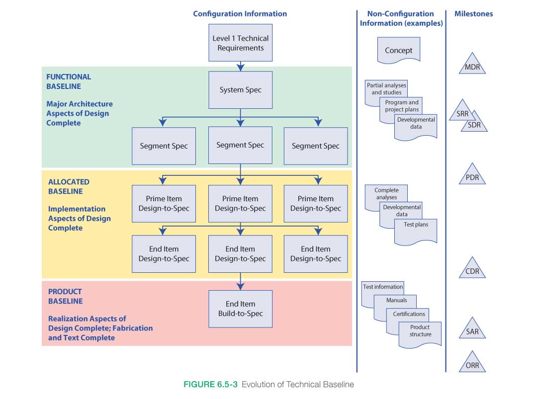
The four baselines (see Figure 6.5-3) normally controlled by the program, project, or Center are the following:
- Functional Baseline: The functional baseline is the approved configuration documentation that describes a system’s or top-level CI’s performance requirements (functional, interoperability, and interface characteristics) and the verification required to demonstrate the achievement of those specified characteristics. The functional baseline is established at the SDR by the NASA program/project. The program/project will direct through contractual agreements, how the functional baselines are managed at the different functional levels. (Levels 1–4)
- Allocated Baseline: The allocated baseline is the approved performance-oriented configuration documentation for a CI to be developed that describes the functional, performance, and interface characteristics that are allocated from a higher level requirements document or a CI and the verification required to demonstrate achievement of those specified characteristics. The allocated baseline extends the top-level performance requirements of the functional baseline to sufficient detail for defining the functional and performance characteristics and for initiating detailed design for a CI. The allocated baseline is usually controlled by the design organization until all design requirements have been verified. The allocated baseline is typically established at the successful completion of the PDR. Prior to CDR, NASA normally reviews design output for conformance to design requirements through incremental deliveries of engineering data. NASA control of the allocated baseline occurs through review of the engineering deliveries as data items.
- Product Baseline: The product baseline is the approved technical documentation that describes the configuration of a CI during the production, fielding/deployment, and operational support phases of its life cycle. The established product baseline is controlled as described in the configuration management plan that was developed during Phase A. The product baseline is typically established at the completion of the CDR. The product baseline describes:
- Detailed physical or form, fit, and function characteristics of a CI;
- The selected functional characteristics designated for production acceptance testing; and
- The production acceptance test requirements.
- As-Deployed Baseline: The as-deployed baseline occurs at the ORR. At this point, the design is considered to be functional and ready for flight. All changes will have been incorporated into the documentation.
6.5.1.2.3 Manage Configuration Change Control
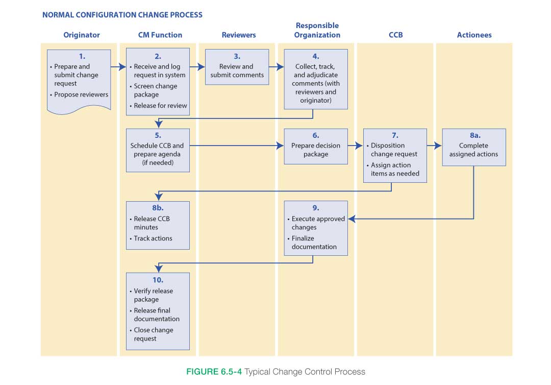
Configuration change management is a process to manage approved designs and the implementation of approved changes. Configuration change management is achieved through the systematic proposal, justification, and evaluation of proposed changes followed by incorporation of approved changes and verification of implementation. Implementing configuration change management in a given program/project requires unique knowledge of the program/project objectives and requirements. The first step establishes a robust and well-disciplined internal NASA Configuration Control Board (CCB) system, which is chaired by someone with program/project change authority. CCB members represent the stakeholders with authority to commit the team they represent. The second step creates configuration change management surveillance of the contractor’s activity. The CM office advises the NASA program or project manager to achieve a balanced configuration change management implementation that suits the unique program/project situation. See Figure 6.5-4 for an example of a typical configuration change management control process.
Types of Configuration Management Changes
- Engineering Change: An engineering change is an iteration in the baseline. Changes can be major or minor. They may or may not include a specification change. Changes affecting an external interface must be coordinated and approved by all stakeholders affected.
- A “major” change is a change to the baseline configuration documentation that has significant impact (i.e., requires retrofit of delivered products or affects the baseline specification, cost, safety, compatibility with interfacing products, or operator, or maintenance training).
- A ”minor” change corrects or modifies configuration documentation or processes without impact to the interchangeability of products or system elements in the system structure.
- Waiver: A waiver is a documented agreement intentionally releasing a program or project from meeting a requirement. (Some Centers use deviations prior to Implementation and waivers during Implementation.) Authorized waivers do not constitute a change to a baseline.
6.5.1.2.4 Maintain the Status of Configuration Documentation
Configuration Status Accounting (CSA) is the recording and reporting of configuration data necessary to manage CIs effectively. An effective CSA system provides timely and accurate configuration information such as:
- Complete current and historical configuration documentation and unique identifiers.
- Status of proposed changes, deviations, and waivers from initiation to implementation.
- Status and final disposition of identified discrepancies and actions identified during each configuration audit.
Some useful purposes of the CSA data include:
- An aid for proposed change evaluations, change decisions, investigations of design problems, warranties, and shelf-life calculations
- Historical traceability
- Software trouble reporting
- Performance measurement data
The following are critical functions or attributes to consider if designing or purchasing software to assist with the task of managing configuration.
- Ability to share data real time with internal and external stakeholders securely;
- Version control and comparison (track history of an object or product);
- Secure user checkout and check in;
- Tracking capabilities for gathering metrics (i.e., time, date, who, time in phases, etc.);
- Web based;
- Notification capability via e-mail;
- Integration with other databases or legacy systems;
- Compatible with required support contractors and/or suppliers (i.e., can accept data from a third party as required);
- Integration with drafting and modeling programs as required;
- Provide neutral format viewer for users;
- License agreement allows for multiple users within an agreed-to number;
- Workflow and life cycle management;
- Limited customization;
- Migration support for software upgrades;
- User friendly;
- Consideration for users with limited access;
- Ability to attach standard format files from desktop
- Workflow capability (i.e., route a CI as required based on a specific set of criteria); and
- Capable of acting as the one and only source for released information.
6.4.1.2.5 Conduct Configuration Audits
Configuration verification is accomplished by inspecting documents, products, and records; reviewing procedures, processes, and systems of operations to verify that the product has achieved its required performance requirements and functional attributes; and verifying that the product’s design is documented. This is sometimes divided into functional and physical configuration audits. (See Section 6.7.2.3 for more on technical reviews.)
6.4.1.2.6 Capture work Products
These include the strategy and procedures for configuration management, the list of identified configuration items, descriptions of the configuration items, change requests, disposition of the requests, rational for dispositions, reports, and audit results.
6.5.1.3 Outputs
NPR 7120.5 defines a project’s life cycle in progressive phases. Beginning with Pre-Phase A, these steps in turn are grouped under the headings of Formulation and Implementation. Approval is required to transition between these phases. Key Decision Points (KDPs) define transitions between the phases. CM plays an important role in determining whether a KDP has been met. Major outputs of CM are:
- List of configuration items under control (Configuration Status Accounting (CSA) reports): This output is the list of all the items, documents, hardware, software, models, etc., that were identified as needing to be placed under configuration control. CSA reports are updated and maintained throughout the program and project life cycle.
- Current baselines: Baselines of the current configurations of all items that are on the CM list are made available to all technical teams and stakeholders.
- CM reports: Periodic reports on the status of the CM items should be available to all stakeholders on an agreed-to frequency and at key life cycle reviews.
- Other CM work products: Other work products include the strategy and procedures used for CM; descriptions, drawings and/or models of the CM items; change requests and their disposition and accompanying rationale; reports; audit results as well as any corrective actions needed.
6.5.2 CM Guidance
Refer to Section 6.5.2 in the NASA Expanded Guidance for Systems Engineering at https://nen.nasa.gov/web/se/doc-repository for additional guidance on:
the impact of not doing CM,
- warning signs when you know you are in trouble, and
- when it is acceptable to use redline drawings.