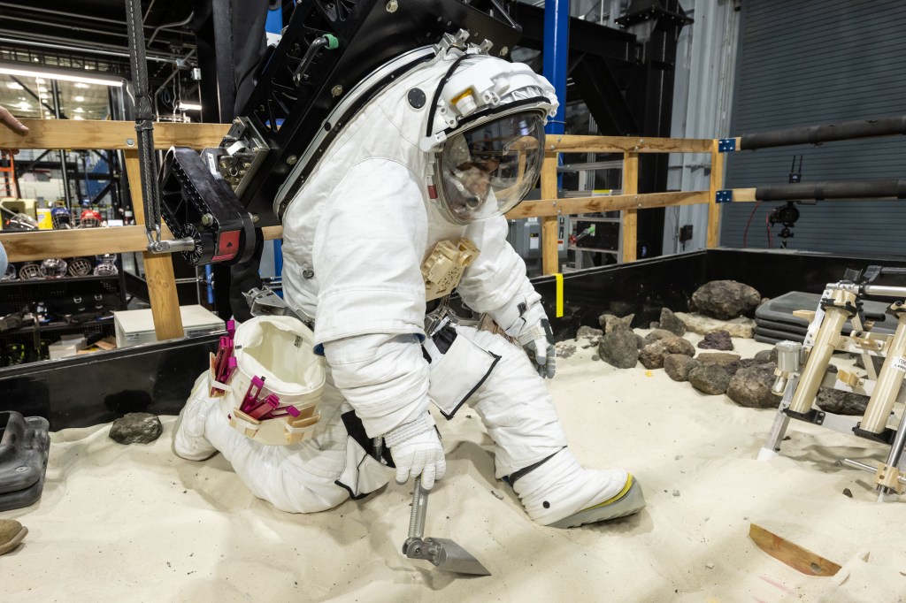
5.1 Product Implementation
5.2 Product Integration
5.3 Product Verification
5.4 Product Validation
5.5 Product Transition
Product integration is a key activity of the systems engineer. Product integration is the engineering of the subsystem interactions and their interactions with the system environments (both natural and induced). Also in this process, lower-level products are assembled into higher-level products and checked to make sure that the integrated product functions properly and that there are no adverse emergent behaviors. This integration begins during concept definition and continues throughout the system life cycle. Integration involves several activities focused on the interactions of the subsystems and environments. These include system analysis to define and understand the interactions, development testing including qualification testing, and integration with external systems (e.g., launch operations centers, space vehicles, mission operations centers, flight control centers, and aircraft) and objects (i.e., planetary bodies or structures). To accomplish this integration, the systems engineer is active in integrating the different discipline and design teams to ensure system and environmental interactions are being properly balanced by the differing design teams. The result of a well-integrated and balanced system is an elegant design and operation.
Integration begins with concept development, ensuring that the system concept has all necessary functions and major elements and that the induced and natural environment domains in which the system is expected to operate are all identified. Integration continues during requirements development, ensuring that all system and environmental requirements are compatible and that the system has a proper balance of functional utility to produce a robust and efficient system. Interfaces are defined in this phase and are the pathway of system interactions. Interfaces include mechanical (i.e., structure, loads), fluids, thermal, electrical, data, logical (i.e., algorithms and software), and human. These interfaces may include support for assembly, maintenance, and testing functions in addition to the system main performance functions. The interactions that occur through all of these interfaces can be subtle and complex, leading to both intended and unintended consequences. All of these interactions need to be engineered to produce an elegant and balanced system.
Integration during the design phase continues the engineering of these interactions and requires constant analysis and management of the subsystem functions and the subsystem interactions between themselves and with their environments. Analysis of the system interactions and managing the balance of the system is the central function of the systems engineer during the design process. The system needs to create and maintain a balance between the subsystems, optimizing the system performance over any one subsystem to achieve an elegant and efficient design. The design phase often involves development testing at the component, assembly, or system level. This is a key source of data on system interactions, and the developmental test program should be structured to include subsystem interactions, human-in-the-loop evaluations, and environmental interaction test data as appropriate.
Integration continues during the operations phase, bringing together the system hardware, software, and human operators to perform the mission. The interactions between these three integrated natures of the system need to be managed throughout development and into operations for mission success. The systems engineer, program manager, and the operations team (including the flight crew from crewed missions) need to work together to perform this management. The systems engineer is not only cognizant of these operations team interactions, but is also involved in the design responses and updates to changes in mission parameters and unintended consequences (through fault management).
Finally, integration or de-integration occurs during system closeout (i.e., decommissioning and disposal). The system capabilities to support de-integration and/or disposal need to be engineered into the system from the concept definition phase. The closeout phase involves the safe disposal of flight assets consistent with U.S. policy and law and international treaties. This disposal can involve the safe reentry and recovery or impact in the ocean, impact on the moon, or solar trajectory. This can also involve the disassembly or repurposing of terrestrial equipment used in manufacturing, assembly, launch, and flight operations. Dispositioning of recovered flight assets also occurs during this phase. Capture of system data and archiving for use in future analysis also occurs. In all of these activities, the systems engineer is involved in ensuring a smooth and logical disassembly of the system and associated program assets.
The Product Integration Process applies not only to hardware and software systems but also to service-oriented solutions, requirements, specifications, plans, and concepts. The ultimate purpose of product integration is to ensure that the system elements function as a whole.
Product integration involves many activities that need to be planned early in the program or project in order to effectively and timely accomplish the integration. Some integration activities (such as system tests) can require many years of work and costs that need to be identified and approved through the budget cycles. An integration plan should be developed and documented to capture this planning. Small projects and activities may be able to include this as part of their SEMP. Some activities may have their integration plans captured under the integration plan of the sponsoring flight program or R&T program. Larger programs and projects need to have a separate integration plan to clearly lay out the complex analysis and tests that need to occur. An example outline for a separate integration plan is provided in Appendix H.
During project closeout, a separate closeout plan should be produced describing the decommissioning and disposal of program assets. (For example, see National Space Transportation System (NSTS) 60576, Space Shuttle Program, Transition Management Plan). For smaller projects and activities, particularly with short life cycles (i.e., short mission durations), the closeout plans may be contained in the SEMP.
5.2.1 Process Description
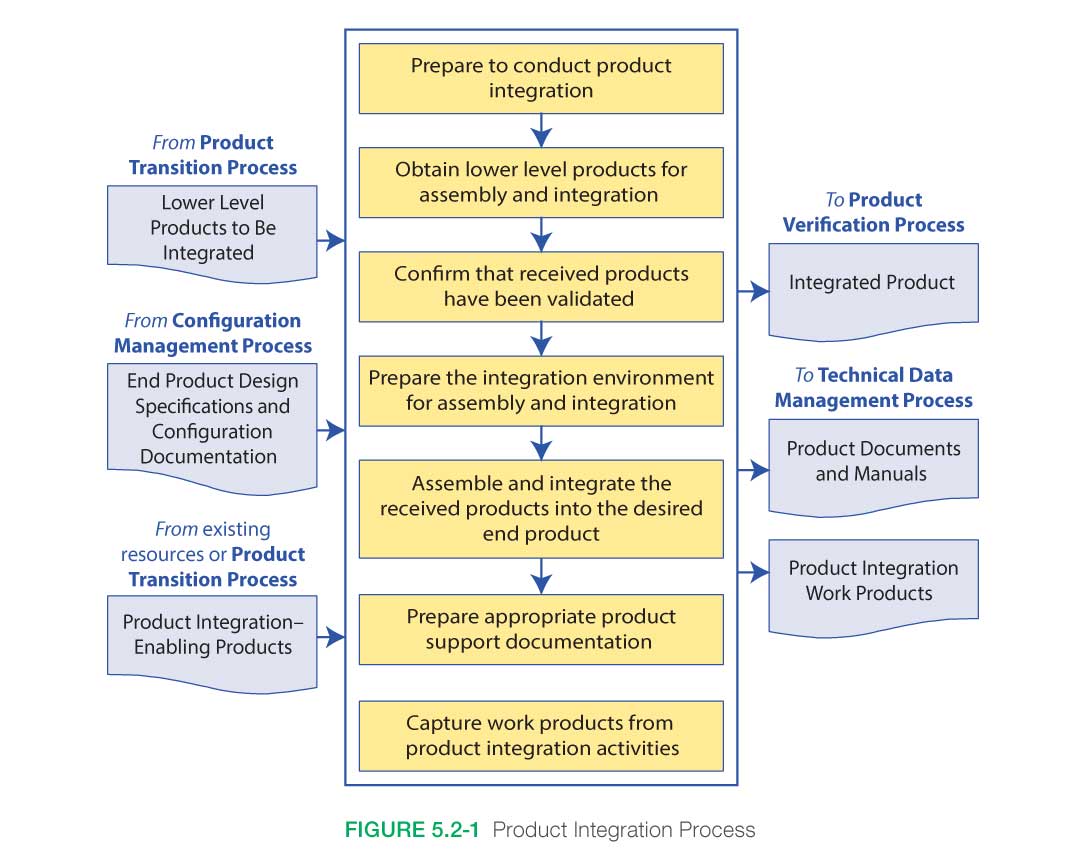
Figure 5.2-1 provides a typical flow diagram for the Product Integration Process and identifies typical inputs, outputs, and activities to consider in addressing product integration. The activities of the Product Integration Process are truncated to indicate the action and object of the action.
5.2.1.1 Inputs
- Lower-level products to be integrated: These are the products developed in the previous lower-level tier in the product hierarchy. These products will be integrated/assembled to generate the product for this product layer.
- End product design specifications and configuration documentation: These are the specifications, Interface Control Documents (ICDs), drawings, integration plan, procedures, or other documentation or models needed to perform the integration including documentation for each of the lower-level products to be integrated.
- Product integration-enabling products: These would include any enabling products, such as holding fixtures, necessary to successfully integrate the lower-level products to create the end product for this product layer.
5.2.1.2 Process Activities
This subsection addresses the approach to the implementation of the Product Integration Process, including the activities required to support the process. The basic tasks that need to be established involve the management of internal and external interactions of the various levels of products and operator tasks to support product integration and are as follows:
5.2.1.2.1 Prepare to Conduct Product Integration
Prepare to conduct product integration by (1) reviewing the product integration strategy/plan (see Section 6.1.2.4.4), generating detailed planning for the integration, and developing integration sequences and procedures; and (2) determining whether the product configuration documentation is adequate to conduct the type of product integration applicable for the product life cycle phase, location of the product in the system structure, and management phase success criteria.
An integration strategy is developed and documented in an integration plan. This plan, as well as supporting documentation, identifies the optimal sequence of receipt, assembly, and activation of the various components that make up the system. This strategy should use technical, cost, and schedule factors to ensure an assembly, activation, and loading sequence that minimizes cost and assembly difficulties. The larger or more complex the system or the more delicate the element, the more critical the proper sequence becomes, as small changes can cause large impacts on project results.
The optimal sequence of assembly is built from the bottom up as components become sub-elements, elements, and subsystems, each of which should be checked prior to fitting it into the next higher assembly. The sequence will encompass any effort needed to establish and equip the assembly facilities; e.g., raised floor, hoists, jigs, test equipment, input/output, and power connections. Once established, the sequence should be periodically reviewed to ensure that variations in production and delivery schedules have not had an adverse impact on the sequence or compromised the factors on which earlier decisions were made.
5.2.1.2.2 Obtain Lower-Level Products for Assembly and Integration
Each of the lower-level products that is needed for assembly and integration is obtained from the transitioning lower-level product owners or a storage facility as appropriate. Received products should be inspected to ensure no damages occurred during the transitioning process.
5.2.1.2.3 Confirm That Received Products Have Been Validated
Confirm that the received products that are to be assembled and integrated have been validated to demonstrate that the individual products satisfy the agreed-to set of stakeholder expectations, including interface requirements. This validation can be conducted by the receiving organization or by the providing organization if fully documented or witnessed by the receiving representative.
5.2.1.2.4 Prepare the Integration Environment for Assembly and Integration
Prepare the integration environment in which assembly and integration will take place, including evaluating the readiness of the product integration-enabling products and the assigned workforce. These enabling products may include facilities, equipment jigs, tooling, and assembly/production lines. The integration environment includes test equipment, simulators, models, storage areas, and recording devices.
5.2.1.2.5 Assemble and Integrate the Received Products into the Desired End Product
Assemble and integrate the received products into the desired end product in accordance with the specified requirements, configuration documentation, interface requirements, applicable standards, and integration sequencing and procedures. This activity includes managing, evaluating, and controlling physical, functional, and data interfaces among the products being integrated.
Functional testing of the assembled or integrated unit is conducted to ensure that assembly is ready to enter verification testing and ready to be integrated into the next level. Typically, all or key representative functions are checked to ensure that the assembled system is functioning as expected. Formal product verification and validation will be performed in the next process.
5.2.1.2.6 Prepare Appropriate Product Support
Documentation
Prepare appropriate product support documentation, such as special procedures for performing product verification and product validation. Drawings or accurate models of the assembled system are developed and confirmed to be representative of the assembled system.
5.2.1.2.7 Capture Product Integration Work Products
Capture work products and related information generated while performing the Product Integration Process activities. These work products include system models, system analysis data and assessment reports, derived requirements, the procedures that were used in the assembly, decisions made and supporting rationale, assumptions that were made, identified anomalies and associated corrective actions, lessons learned in performing the assembly, and updated product configuration and support documentation.
5.2.1.3 Outputs
The following are typical outputs from this process and destinations for the products from this process:
- Integrated product(s) with all system interactions identified and properly balanced.
- Documentation and manuals, including system analysis models, data, and reports supporting flight-readiness rationale and available for future analysis during the operation of the system in the mission-execution phase.
- Work products, including reports, records, and non-deliverable outcomes of product integration activities (to support the Technical Data Management Process); integration strategy document; assembly/check area drawings; system/component documentation sequences and rationale for selected assemblies; interface management documentation; personnel requirements; special handling requirements; system documentation; shipping schedules; test equipment and drivers’ requirements; emulator requirements; and identification of limitations for both hardware and software.
5.2.2 Product Integration Guidance
Refer to Section 5.2.2 in the NASA Expanded Guidance for Systems Engineering at https://nen.nasa.gov/web/se/doc-repository for additional guidance on:
- product integration strategies,
- the relationship to product implementation,
- product integration support,
- product integration of the design solution,
- system analysis, and
- interface system integration.


