


SEH 2.0 Fundamentals of Systems Engineering
Encyclopedia
Updated Feb 6, 2019
Contents
- 2.1 The Common Technical Processes and the SE Engine
- 2.2 An Overview of the SE Engine by Project Phase
- 2.3 Example of Using the SE Engine
- 2.4 Distinctions between Product Verification and Product Validation
- 2.5 Cost Effectiveness Considerations
- 2.6 Human Systems Integration (HSI) in the SE Process
- 2.7 Competency Model for Systems Engineers
At NASA, “systems engineering” is defined as a methodical, multi-disciplinary approach for the design, realization, technical management, operations, and retirement of a system. A “system” is the combination of elements that function together to produce the capability required to meet a need. The elements include all hardware, software, equipment, facilities, personnel, processes, and procedures needed for this purpose; that is, all things required to produce system-level results. The results include system-level qualities, properties, characteristics, functions, behavior, and performance. The value added by the system as a whole, beyond that contributed independently by the parts, is primarily created by the relationship among the parts; that is, how they are interconnected. It is a way of looking at the “big picture” when making technical decisions. It is a way of achieving stakeholder functional, physical, and operational performance requirements in the intended use environment over the planned life of the system within cost, schedule, and other constraints. It is a methodology that supports the containment of the life cycle cost of a system. In other words, systems engineering is a logical way of thinking.
Systems engineering is the art and science of developing an operable system capable of meeting requirements within often opposed constraints. Systems engineering is a holistic, integrative discipline, wherein the contributions of structural engineers, electrical engineers, mechanism designers, power engineers, human factors engineers, and many more disciplines are evaluated and balanced, one against another, to produce a coherent whole that is not dominated by the perspective of a single discipline.
Systems engineering seeks a safe and balanced design in the face of opposing interests and multiple, sometimes conflicting constraints. The systems engineer should develop the skill for identifying and focusing efforts on assessments to optimize the overall design and not favor one system/subsystem at the expense of another while constantly validating that the goals of the operational system will be met. The art is in knowing when and where to probe. Personnel with these skills are usually tagged as “systems engineers.” They may have other titles—lead systems engineer, technical manager, chief engineer—but for this document, the term “systems engineer” is used.
The exact role and responsibility of the systems engineer may change from project to project depending on the size and complexity of the project and from phase to phase of the life cycle. For large projects, there may be one or more systems engineers. For small projects, the project manager may sometimes perform these practices. But whoever assumes those responsibilities, the systems engineering functions should be performed. The actual assignment of the roles and responsibilities of the named systems engineer may also therefore vary. The lead systems engineer ensures that the system technically fulfills the defined needs and requirements and that a proper systems engineering approach is being followed. The systems engineer oversees the project’s systems engineering activities as performed by the technical team and directs, communicates, monitors, and coordinates tasks. The systems engineer reviews and evaluates the technical aspects of the project to ensure that the systems/subsystems engineering processes are functioning properly and evolves the system from concept to product. The entire technical team is involved in the systems engineering process.
The systems engineer usually plays the key role in leading the development of the concept of operations (ConOps) and resulting system architecture, defining boundaries, defining and allocating requirements, evaluating design tradeoffs, balancing technical risk between systems, defining and assessing interfaces, and providing oversight of verification and validation activities, as well as many other tasks. The systems engineer typically leads the technical planning effort and has the prime responsibility in documenting many of the technical plans, requirements and specification documents, verification and validation documents, certification packages, and other technical documentation.
In summary, the systems engineer is skilled in the art and science of balancing organizational, cost, and technical interactions in complex systems. The systems engineer and supporting organization are vital to supporting program and Project Planning and Control (PP&C) with accurate and timely cost and schedule information for the technical activities. Systems engineering is about tradeoffs and compromises; it uses a broad crosscutting view of the system rather than a single discipline view. Systems engineering is about looking at the “big picture” and not only ensuring that they get the design right (meet requirements) but that they also get the right design (enable operational goals and meet stakeholder expectations).
Systems engineering plays a key role in the project organization. Managing a project consists of three main objectives: managing the technical aspects of the project, managing the project team, and managing the cost and schedule. As shown in Figure 2.0-1, these three functions are interrelated. Systems engineering is focused on the technical characteristics of decisions including technical, cost, and schedule and on providing these to the project manager. The Project Planning and Control (PP&C) function is responsible for identifying and controlling the cost and schedules of the project. The project manager has overall responsibility for managing the project team and ensuring that the project delivers a technically correct system within cost and schedule. Note that there are areas where the two cornerstones of project management, SE and PP&C, overlap. In these areas, SE provides the technical aspects or inputs whereas PP&C provides the programmatic, cost, and schedule inputs.
This document focuses on the SE side of the diagram. The practices/processes are taken from NPR 7123.1, NASA Systems Engineering Processes and Requirements. Each process is described in much greater detail in subsequent chapters of this document, but an overview is given in the following subsections of this chapter.
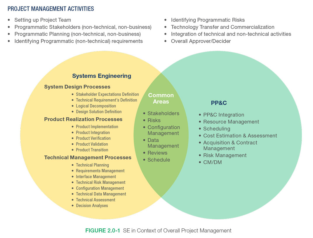
Figure 2.0-1 Systems Engineering in Context of Overall Project Management
2.1 The Common Technical Processes and the SE Engine
There are three sets of common technical processes in NPR 7123.1, NASA Systems Engineering Processes and Requirements: system design, product realization, and technical management. The processes in each set and their interactions and flows are illustrated by the NPR systems engineering “engine” shown in Figure 2.1-1. The processes of the SE engine are used to develop and realize the end products. This chapter provides the application context of the 17 common technical processes required in NPR7123.1. The system design processes, the product realization processes, and the technical management processes are discussed in more detail in Chapters 4.0, 5.0, and 6.0, respectively. Processes 1 through 9 indicated in Figure 2.1-1 represent the tasks in the execution of a project. Processes 10 through 17 are crosscutting tools for carrying out the processes.
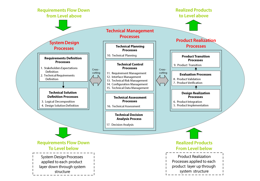
Figure 2.1-1 The Systems Engineering Engine (NPR 7123.1)
- System Design Processes: The four system design processes shown in Figure 2.1-1 are used to define and baseline stakeholder expectations, generate and baseline technical requirements, decompose the requirements into logical and behavioral models, and convert the technical requirements into a design solution that will satisfy the baselined stakeholder expectations. These processes are applied to each product of the system structure from the top of the structure to the bottom until the lowest products in any system structure branch are defined to the point where they can be built, bought, or reused. All other products in the system structure are realized by implementation or integration.
- Product Realization Processes: The product realization processes are applied to each operational/mission product in the system structure starting from the lowest level product and working up to higher level integrated products. These processes are used to create the design solution for each product (through buying, coding, building, or reusing) and to verify, validate, and transition up to the next hierarchical level those products that satisfy their design solutions and meet stakeholder expectations as a function of the applicable life cycle phase.
- Technical Management Processes: The technical management processes are used to establish and evolve technical plans for the project, to manage communication across interfaces, to assess progress against the plans and requirements for the system products or services, to control technical execution of the project through to completion, and to aid in the decision-making process.
The processes within the SE engine are used both iteratively and recursively. As defined in NPR 7123.1, “iterative” is the “application of a process to the same product or set of products to correct a discovered discrepancy or other variation from requirements,” whereas “recursive” is defined as adding value to the system “by the repeated application of processes to design next lower layer system products or to realize next upper layer end products within the system structure. This also applies to repeating application of the same processes to the system structure in the next life cycle phase to mature the system definition and satisfy phase success criteria.” The technical processes are applied recursively and iteratively to break down the initializing concepts of the system to a level of detail concrete enough that the technical team can implement a product from the information. Then the processes are applied recursively and iteratively to integrate the smallest product into greater and larger systems until the whole of the system or product has been assembled, verified, validated, and transitioned.
For a detailed example of how the SE Engine could be used, refer to the NASA Expanded Guidance for SE document at https://nen.nasa.gov/web/se/doc-repository.
AS9100 is a widely adopted and standardized quality management system developed for the commercial aerospace industry. Some NASA Centers have chosen to certify to the AS9100 quality system and may require their contractors to follow NPR 7123.1. Table 2.1-1 shows how the 17 NASA SE processes align with AS9100.
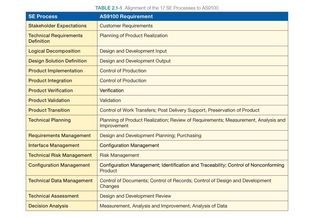
Table 2.1-1 Alignment of the 17 SE Processes to AS9100
2.2 An Overview of the SE Engine by Project Phase
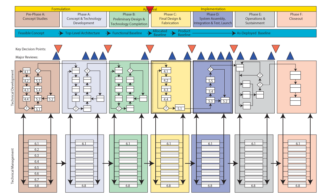
Figure 2.2-1 Miniature Version of the Poster-Size NASA Project Life Cycle Process Flow for Flight and Ground Systems Accompanying this Handbook
Figure 2.2-1 conceptually illustrates how the SE engine is used during each phase of a project (Pre-Phase A through Phase F). The life cycle phases are described in Table 2.2-1. Figure 2.2-1 is a conceptual diagram. For full details, refer to the poster version of this figure, which is located at https://nen.nasa.gov/web/se/doc-repository.
The uppermost horizontal portion of this chart is used as a reference to project system maturity, as the project progresses from a feasible concept to an as-deployed system; phase activities; Key Decision Points (KDPs); and major project reviews. The next major horizontal band shows the technical development processes (steps 1 through 9) in each project phase. The SE engine cycles five times from Pre-Phase A through Phase D. Note that NASA’s management has structured Phases C and D to “split” the technical development processes in half in Phases C and D to ensure closer management control. The engine is bound by a dashed line in Phases C and D. Once a project enters into its operational state (Phase E) and closes out (Phase F), the technical work shifts to activities commensurate with these last two project phases. The next major horizontal band shows the eight technical management processes (steps 10 through 17) in each project phase. The SE engine cycles the technical management processes seven times from Pre-Phase A through Phase F.
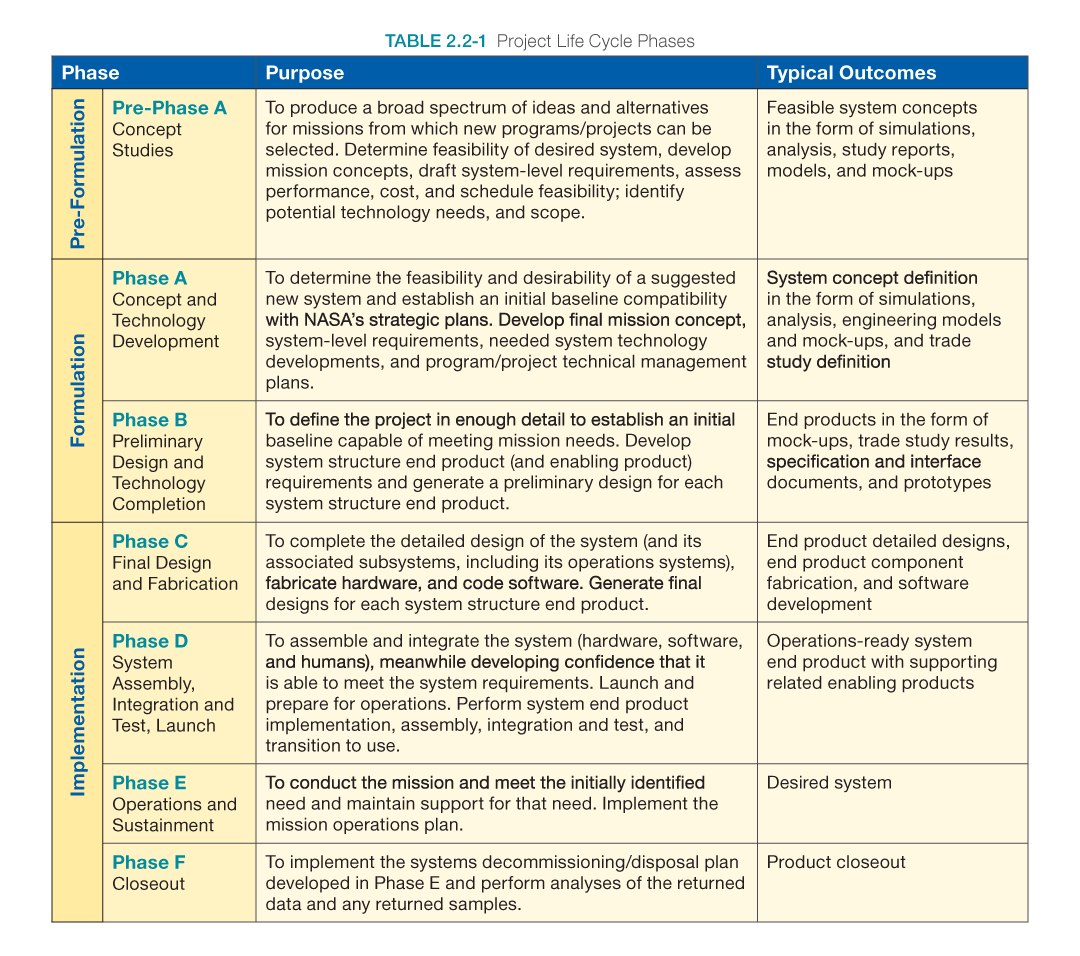
Table 2.2-1 Project Life Cycle Phases
2.3 Example of Using the SE Engine
In Pre-Phase A, the SE engine is used to develop the initial concepts; clearly define the unique roles of humans, hardware, and software in performing the missions objectives; establish the system functional and performance boundaries; develop/identify a preliminary/draft set of key high-level requirements, define one or more initial Concept of Operations (ConOps) scenarios; realize these concepts through iterative modeling, mock-ups, simulation, or other means; and verify and validate that these concepts and products would be able to meet the key high-level requirements and ConOps. The operational concept must include scenarios for all significant operational situations, including known off-nominal situations. To develop a useful and complete set of scenarios, important malfunctions and degraded-mode operational situations must be considered. The importance of early ConOps development cannot be underestimated. As system requirements become more detailed and contain more complex technical information, it becomes harder for the stakeholders and users to understand what the requirements are conveying; i.e., it may become more difficult to visualize the end product. The ConOps can serve as a check in identifying missing or conflicting requirements.
During Phase A, the recursive use of the SE engine is continued, this time taking the concepts and draft key requirements that were developed and validated during Pre-Phase A and fleshing them out to become the set of baseline system requirements and ConOps. During this phase, key areas of high risk might be simulated to ensure that the concepts and requirements being developed are good ones and to identify verification and validation tools and techniques that will be needed in later phases.
Note that this Pre-Phase A initial concepts development work is not the formal verification and validation program that is performed on the final product, but rather it is a methodical run through ensuring that the concepts that are being developed in this Pre-Phase A are able to meet the likely requirements and expectations of the stakeholders. Concepts are developed to the lowest level necessary to ensure that they are feasible and to a level that reduces the risk low enough to satisfy the project. Academically, this process could proceed down to the circuit board level for every system; however, that would involve a great deal of time and money. There may be a higher level or tier of product than circuit board level that would enable designers to accurately determine the feasibility of accomplishing the project, which is the purpose of Pre-Phase A.
During Phase B, the SE engine is applied recursively to further mature requirements and designs for all products in the developing product tree and perform verification and validation of concepts to ensure that the designs are able to meet their requirements. Operational designs and mission scenarios are evaluated and feasibility of execution within design capabilities and cost estimates are assessed.
Phase C again uses the left side of the SE engine to finalize all requirement updates, finalize the ConOps validation, develop the final designs to the lowest level of the product tree, and begin fabrication.
Phase D uses the right side of the SE engine to recursively perform the final implementation, integration, verification, and validation of the end product, and at the final pass, transition the end product to the user.
The technical management processes of the SE engine are used in Phases E and F to monitor performance; control configuration; and make decisions associated with the operations, sustaining engineering, and closeout of the system. Any new capabilities or upgrades of the existing system reenter the SE engine as new developments.
2.4 Distinctions between Product Verification and Product Validation
From a process perspective, the Product Verification and Product Validation processes may be similar in nature, but the objectives are fundamentally different:
- Verification of a product shows proof of compliance with requirements—that the product can meet each “shall” statement as proven though performance of a test, analysis, inspection, or demonstration (or combination of these).
- Validation of a product shows that the product accomplishes the intended purpose in the intended environment—that it meets the expectations of the customer and other stakeholders as shown through performance of a test, analysis, inspection, or demonstration.
Verification testing relates back to the approved requirements set and can be performed at different stages in the product life cycle. The approved specifications, drawings, parts lists, and other configuration documentation establish the configuration baseline of that product, which may have to be modified at a later time. Without a verified baseline and appropriate configuration controls, later modifications could be costly or cause major performance problems.
Validation relates back to the ConOps document. Validation testing is conducted under realistic conditions (or simulated conditions) on end products for the purpose of determining the effectiveness and suitability of the product for use in mission operations by typical users. Validation can be performed in each development phase using phase products (e.g., models) and not only at delivery using end products.
It is appropriate for verification and validation methods to differ between phases as designs advance. The ultimate success of a program or project may relate to the frequency and diligence of validation efforts during the design process, especially in Pre-Phase A and Phase A during which corrections in the direction of product design might still be made cost-effectively. The question should be continually asked, “Are we building the right product for our users and other stakeholders?” The selection of the verification or validation method is based on engineering judgment as to which is the most effective way to reliably show the product’s conformance to requirements or that it will operate as intended and described in the ConOps.
2.5 Cost Effectiveness Considerations
The objective of systems engineering is to see that the system is designed, built, and can be operated so that it accomplishes its purpose safely in the most cost-effective way possible considering performance, cost, schedule, and risk. A cost-effective and safe system should provide a particular kind of balance between effectiveness and cost. This causality is an indefinite one because there are usually many designs that meet the cost-effective condition.
Design trade studies, an important part of the systems engineering process, often attempt to find designs that provide the best combination of cost and effectiveness. At times there are alternatives that either reduce costs without reducing effectiveness or increase effectiveness without increasing cost. In such “win-win” cases, the systems engineer’s decision is easy. When the alternatives in a design trade study require trading cost for effectiveness, the decisions become harder.
The Systems Engineer’s Dilemma
At each cost-effective solution:
- To reduce cost at constant risk, performance must be reduced.
- To reduce risk at constant cost, performance must be reduced.
- To reduce cost at constant performance, higher risks must be accepted.
- To reduce risk at constant performance, higher costs must be accepted.
In this context, time in the schedule is often a critical resource, so that schedule behaves like a kind of cost.
Figure 2.5-1 shows that the life cycle costs of a program or project tend to get “locked in” early in design and development. The cost curves clearly show that late identification of and fixes to problems cost considerably more later in the life cycle. Conversely, descopes taken later versus earlier in the project life cycle result in reduced cost savings. This figure, obtained from the Defense Acquisition University, is an example of how these costs are determined by the early concepts and designs. The numbers will vary from project to project, but the general shape of the curves and the message they send will be similar. For example, the figure shows that during design, only about 15% of the costs might be expended, but the design itself will commit about 75% of the life cycle costs. This is because the way the system is designed will determine how expensive it will be to test, manufacture, integrate, operate, and sustain. If these factors have not been considered during design, they pose significant cost risks later in the life cycle. Also note that the cost to change the design increases as you get later in the life cycle. If the project waits until verification to do any type of test or analysis, any problems found will have a significant cost impact to redesign and reverify.
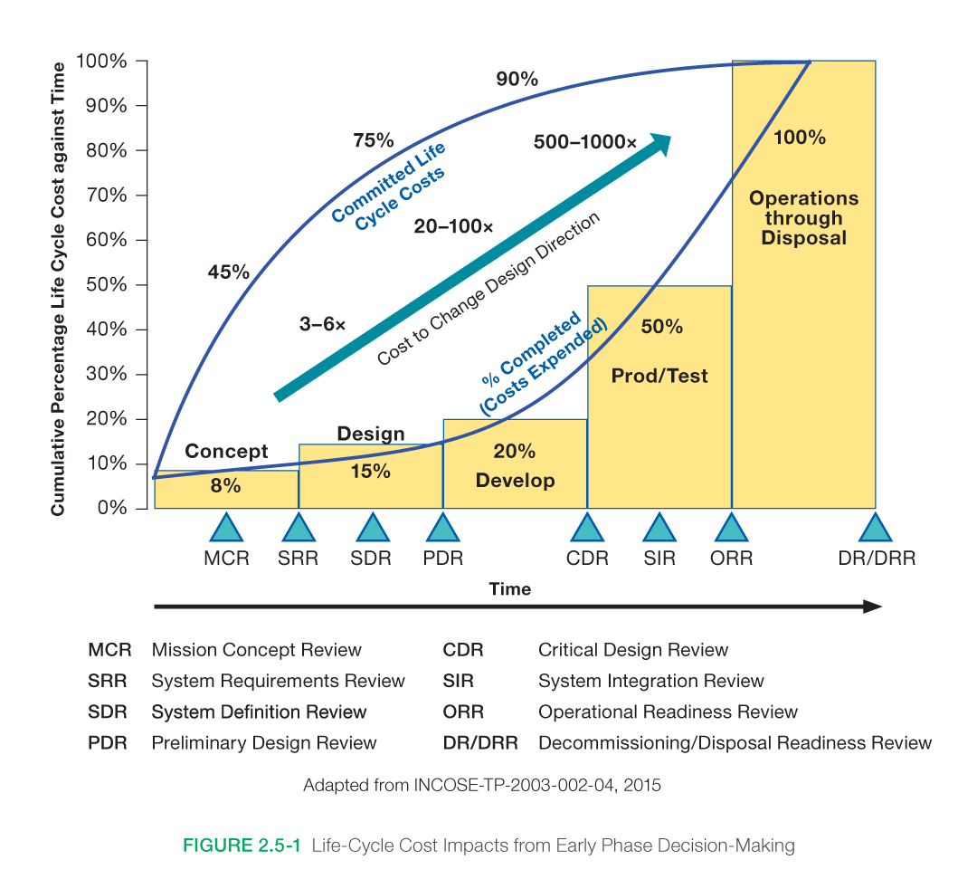
Figure 2.5-1 Life-Cycle Cost Impacts from Early Phase Decision-Making
The technical team may have to choose among designs that differ in terms of numerous attributes. A variety of methods have been developed that can be used to help uncover preferences between attributes and to quantify subjective assessments of relative value. When this can be done, trades between attributes can be assessed quantitatively. Often, however, the attributes are incompatible. In the end, decisions need to be made in spite of the given variety of attributes. There are several decision analysis techniques (Section 6.8) that can aid in complex decision analysis. The systems engineer should always keep in mind the information that needs to be available to help the decision-makers choose the most cost-effective option.
2.6 Human Systems Integration (HSI) in the SE Process
As noted at the beginning of NPR 7123.1, the “systems approach is applied to all elements of a system (i.e., hardware, software, human systems integration. In short, the systems engineering approach must equally address and integrate these three key elements: hardware, software, and human systems integration).” Therefore, the human element is something that integration and systems engineering processes must address. The definition of “system” in NPR 7123.1 is inclusive; i.e., a system is “the combination of elements that function together to produce the capability required to meet a need. The elements include all hardware, software, equipment, facilities, personnel, processes, and procedures needed for this purpose.” For additional information and guidance on his, refer to Section 2.6 of the NASA Expanded Guidance for Systems Engineering at https://nen.nasa.gov/web/se/doc-repository.
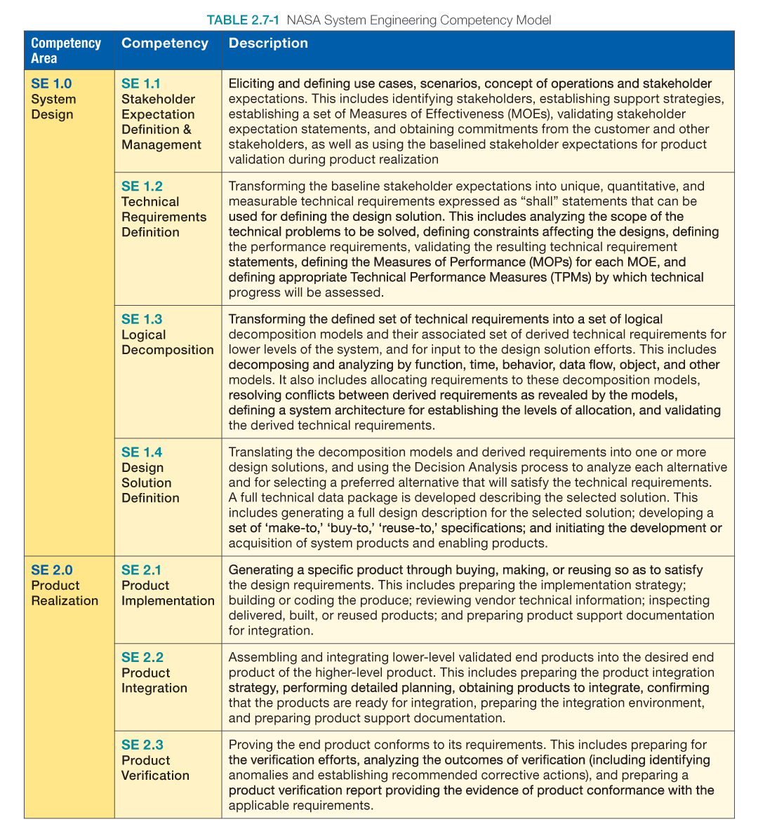
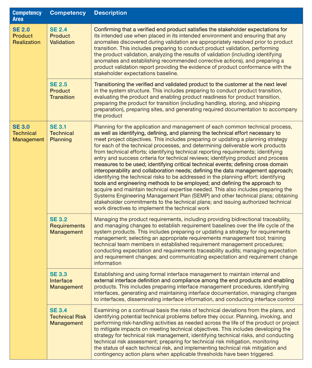
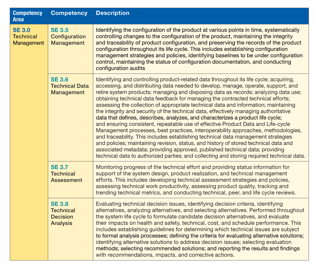
2.7 Competency Model for Systems Engineers
Table 2.7-1 provides a summary of the Competency Model for Systems Engineering. For more information on the NASA SE Competency model refer to: http://appel.nasa.gov/competency-model/.
There are four levels of proficiencies associated with each of these competencies:
- Team Practitioner/Technical Engineer
- Team Lead/Subsystem Lead
- Project Systems Engineer
- Chief Engineer