


Introduction
The Propeller component is perhaps the most complex OpenVSP geometry there is to date. This stems from the fact that there are countless variations of the methods used to design propellers, rotors, proprotors, fans, turbines, compressors, windmills, vanes, etc. and while the most fundamental purpose of each of these is to push or turn air (or other fluidic mediums), the assumptions and even the nomenclature associated with them vary. It is very difficult for a single parameterized model, however complex, to capture the intent behind each of these applications. The OpenVSP Propeller component has been parameterized in such a way that whatever the application, the designer may either directly alter the given parameters or determine a translation between intent and implementation. This tutorial provides a brief introduction to this powerful component and lays out a path for the training content that follows. In this subject page you will learn how to alter the overall shape of the rotor by changing the number of blades, the diameter, and the blade feather or 3/4 radius pitch while also diving into the individual curves that will define the blade profile as well as how to alter the airfoil or section distribution. Additional tutorials are provided that demonstrate the propeller folding parameters and how to alter the tessellation for export to other tools such as CFD grid generators.
Before you add a Propeller to your model, think about why you want it there. Do you know, or at least have a good idea, what your propeller looks like? Will the propeller help you solve a problem or make a decision? Maybe it just looks better that way (and that's okay!). Knowing why you're doing something is as, or more, important than knowing how.

Propeller Design Mode
You can change the visual and functional representation of the Propeller in OpenVSP by altering the Design Mode from “Blades” to “Disk” to “Both”. Choosing “Blades” mode allows the full 3-D propeller model to be shown in the workspace including all surfaces, caps, and tessellation as defined in the design or Blade control curves. “Disk” mode changes the visual representation to that of an actuator disk with the same diameter as the Propeller. An actuator disk is a 2-D representation of the propeller and will not reflect any changes to the blades, coning angle, etc. “Both” will display both the full 3-D model and the actuator disk. As you’ll notice, “Blades” mode can begin to update slowly as more control points are added to the model due to the highly complex parameterization of the Propeller component. In fact, your model may quickly become unwieldly if there are too many points and the propellers are nested with other Parents. However, there is a simple way of making multiple changes to the Propeller at once without waiting for an update each time. Changing the Propeller to “Disk” mode removes the need to visually update the propeller model with each parameter change and enables you to alter almost any parameter instantly. In this way, you can very quickly alter the design as intended and then get back to work. Once your changes are complete, change the Design Mode back to “Blades” and the 3-D model will appear with your updates.
We will note here that the Design Mode is useful in determining which type of propeller/rotor/disk run you would like to choose in VSPAERO. “Blades” mode enables the Rotating Blades option while “Disk” mode enables Actuator Disk. Whichever of these modes is chosen, the other will be greyed out and deactivated to avoid attempting to run with incorrect geometry inputs. This will be covered in more detail in the VSPAERO tutorial sections.
It is perfectly acceptable to place a Prop component in your model and leave it in Disk mode until you are ready to add complexity. In many cases, the actuator disk representation will be all you need for conceptual design.
Propeller Design: Diameter, Blades, and Pitch
In this tutorial, we will discuss how to alter the Propeller diameter, alter the number of blades, and set the blade collective (3/4 radius) pitch or feather angle. In addition to these basic operations, we will also discuss propeller orientation, propeller rotation, and how feather or 3/4 pitch work with the blade twist.
Plan ahead to decide which variable you want to control your blade pitch. You can always switch back and forth but it will save you headaches later when you define your blades consistently from the beginning.
Propeller Design: Precone, Feather, and Construction Axis
In this tutorial, we will discuss how to apply pre-cone and how to alter the construction and feather axes to change how the propeller blades are lofted and rotated. The construction axis, defined by Construct X/C, is how the blade airfoils are placed relative to one another by a chord percentage. For example, a value of 0.0 will align all airfoils at their leading edges while a value of 0.25 will align the airfoils at the quarter-chord location. The feather axis, in contrast, controls where along the blade root chord the feather axis passes through the blade. The entire blade will shift along the root chord direction relative to a fixed feather axis.
These design parameters are intended to set the references for the entire blade. Individual blade sections will be modified under the Blade tab.
Propeller Blade Control Curve Interface
This tutorial introduces the propeller blade control curve interface including how to change the curve type, add or remove control points, interact with the curves, and change values manually. Note that a propeller with many control points will tend to update slowly so you should only use as many control points as needed to obtain the desired profile. An imported BEM model will likely have too many points to function effectively. However, you can choose the Approximate Cubic Bezier option to significantly reduce the number of points and automatically convert to a Bezier curve. Make a copy of your Prop component before converting because you can’t undo this step! You may also choose to automatically convert all curves to Cubic Bezier by clicking the Approximate All button. After conversion, compare the resulting geometry to your original BEM import to ensure that the models sufficiently match.
You can manually drag control points in the Curve Editor grid but until you release the mouse button, the model will not update. Remember that many control points will slow your model down and make it difficult to view changes in real time.
Propeller Blade Chord Curve
The propeller blade Chord curve is defined by the distribution of chord-to-radius (C/R) values and the curve type. For more information about how to manipulate these curves, please refer to the Propeller Blade Control Curve Interface topic.
The C/R is the radius-normalized chord and not a dimensional measurement in fixed units. Changing the radius will scale the chord accordingly.
Propeller Blade Twist Curve
The propeller blade Twist curve is defined by the distribution of twist angles in degrees along the blade and the curve type. The twist angle combined with the blade feather angle will define the local pitch relative to the propeller disk. For more information about how to manipulate these curves, please refer to the Propeller Blade Control Curve Interface topic.
Twist does not set the local blade angle of attack. Twist can be thought of as the angular change along the blade in reference to either the root feather angle or blade collective at 3/4R.
Propeller Blade Rake and Skew Curves
This tutorial covers the propeller Rake and Skew parameters. In contrast to Sweep and Axial, the Rake and Skew are always relative to the local chord orientation rather than the propeller plane of rotation where Rake is normal to the chord and Skew is parallel to the chord. For more information about how to manipulate these curves, please refer to the Propeller Blade Control Curve Interface topic.
Rake and Skew are both normalized by blade radius so the values are often very small. You'll likely want to decrease the range of the slider at first if you're adjusting manually. Make sure that you don't try to combine parameters that have similar effects such as rake and axial.
Propeller Blade Sweep and Axial Curves
This tutorial covers the propeller Sweep and Axial parameters. In contrast to Skew and Rake, the Sweep and Axial are always relative to the propeller plane of rotation rather than the local chord orientation. Sweep is an angular rotation of the blade section (positive against the direction of rotation) in the plane and Axial is a translation of the blade section normal to the plane (positive against the thrust direction). Note that Axial differs from Pre-cone in that the section is translated rather than rotated and may be applied along the blade rather than to the entire blade at once. For more information about how to manipulate these curves, please refer to the Propeller Blade Control Curve Interface topic.
Try not to combine similar parameters such as axial and rake or sweep and skew unless you have a very good justification for doing so. In almost all cases, you can achieve the desired shape using only one set of these.
Propeller Blade Tangential Curve
This tutorial covers the propeller Tangential parameter. This parameter translates the blade section normal to the blade construction axis within the propeller plane of rotation either with or against the direction of rotation. Tangential differs from Sweep in that Sweep is a rotation of the blade section about the propeller thrust axis while Tangential is a translation in a straight direction normal to the blade construction axis. For example, a propeller thrusting in the negative X direction exhibits Tangential shifts of the first blade in the +/- Z direction, assuming no prop rotation. For more information about how to manipulate these curves, please refer to the Propeller Blade Control Curve Interface topic.
In the rotation plane, excessive tangential will cause your root or tip faces to become trailing faces. Similarly, your airfoils will no longer be "flow aligned" in the rotation direction. Use with caution.
Propeller Blade Thickness Curve
This tutorial covers the propeller blade Thickness curve. This curve defines the cross-section thickness-to-chord ratio along the blade for whatever type of section is set. For airfoils, this value is relatively straightforward since T/C is a common defining characteristic of these shapes. Other section types, such as ellipses or rectangles, have their width set by the chord (C/R) and the height set by T/C automatically. For more information about how to manipulate these curves, please refer to the Propeller Blade Control Curve Interface topic.
Note that the XSec values for height and width or chord and T/C are deactivated for propeller components as these values are controlled by the Chord and Thick curves! AF_File (custom airfoil) types will have their base T/C overridden by the T/C curve. To apply a specific T/C at a given blade station, you must have a curve control point at that station and set the desired T/C. You also have the option of resetting all AF cross-section thicknesses to their computed Base T/C by clicking Reset Thick under the Curve Editor region in the Blade tab.
OpenVSP will blend the blade thickness along the radius according to your curve type. Unless you enforce transition regions between airfoils by using two adjacent XSec very near each other, understand that you will have a constantly varying airfoil definition along the blade.
Propeller Blade Ideal Lift Curve
This tutorial covers the propeller blade CLi curve. This curve defines the cross-section ideal lift coefficient along the blade for airfoil section types. For airfoils, this value is relatively straightforward since CLi is a common defining characteristic of these shapes or may be solved for using other parameters like camber. Other section types, such as ellipses or rectangles, do not have camber or similar features and so the CLi values at these stations will have no effect at that blade station. However, the value will affect the blending between stations. Custom airfoil file (AF_File) types will NOT have their camber or CLi changed by the curve! For more information about how to manipulate these curves, please refer to the Propeller Blade Control Curve Interface topic.
Note that the XSec values for camber or CLi are deactivated for propeller components as these values are controlled by the CLi curve! To apply a specific CLi at a given blade station, you must have a curve control point at that station and set the desired CLi.
Combining fundamentally different XSec types can lead to confusion if you aren't prepared but can be very advantageous when used wisely.
Propeller Blade Cross-Sections
Due to the unique way that the Prop component operates, there are some specifics to cross-section control that need to be addressed. For many cross-section types such as airfoils, the Chord, Thick, and CLi curves are going to control the overall shape of the section. However, for traditionally body-type sections such as ellipses, rectangles, and General Fuse, the height and width are controlled by the Chord and Thick curves while CLi has no effect as there is no analogous parameter. Custom airfoil files are affected differently. The thickness of the custom airfoil (or other custom section file) will be automatically set by the Thick curve but the camber of the section will remain unaffected. If you wish to have a custom airfoil file retain the proper thickness, you may either input the proper value to the Thick curve at the given blade station or if you are unsure of the value, the Base T/C is calculated for each AF_File under the XSec tab.
The location along the blade (Radius) of cross-section 0 (root) defines the innermost station for the propeller, not the r_0 parameter under the Design tab which is actually the lower limit of activity factor integration. The radius of XSec_0 may be set anywhere between 0.0 and the location of the following section. Similarly, the radius of any Prop cross-section may be set between the radial location of the prior and following cross-sections. The final cross-section radius is always set to 1.0.
Be careful when manipulating your root location or other XSec radial stations as these can cause conflicts and erratic behavior in your blade curves. For example, if you have a root chord control point at 0.2R with XSec0 and another control point at 0.25R, then move XSec0 to 0.25R, the control points will almost directly overlap and the second control point will be pushed to 0.2501R. Normally this isn't an issue if you're building your blades in the GUI but it can wreak havoc in your model if you've automated the process.
Propeller Symmetry Application
As covered in minor detail in the Symmetry with Propellers tutorial, there are multiple ways that you can modify propeller symmetry. These applications are not limited to only traditional propellers but for any geometric shape that you wish to have both axial and planar symmetry about different points. In this example, we show how to create a reflected, counter-rotating propeller across the XZ plane and also how symmetry can be ineffective at producing left/right same-direction propellers. To accomplish such a feature, a copy of the primary propeller should be made and placed on the opposite side manually. For the purposes of actuator disk modeling, this left/right anti-symmetry isn’t an issue and the direction of propeller rotation may be simply altered with the RPM setting.
Remember that component symmetry in OpenVSP is dependent on ancestor references. If you mean to make a propeller symmetrically reflected across a geometry instead of the global origin, the propeller will move with the location of that geometry.
Folding Propeller Hinge Placement
The placement of a propeller folding hinge is defined by the Radial/R, Axial/R, and Offset/R parameters which adjust the location along the blade feather axis, in and out normal to the propeller disk, and “up” or “down” within the propeller disk or normal to the feather axis and thrust directions, respectively. Each of these distances are normalized by the propeller radius so that they remain scaled to the propeller size. The Angle parameter sets the angular rotation about the propeller hinge axis.
OpenVSP v3.40.0 released individual blade folding which enables each blade to be folded by a unique angle. The folding axis and location are all still uniform. Applications include folding helicopter rotor blades aftward for stowage.
Folding Propeller Hinge Orientation
The propeller folding axis orientation is defined by two parameters, Azimuth and Elevation. In this tutorial, we demonstrate how the azimuth and elevation change the direction of the folding axis and provide useful views for observing the axis rotations. Refer to the sections below for additional details.
The Azimuth and Elevation are defined according to the convention shown here in which the azimuthal plane of rotation is the XZ plane or, more specifically, the rotation is about the blade feather axis (+Y in this case) and the elevation is a direct, angular ascension from the azimuth. The propeller hinge rotation axis is the vector -a in this example.
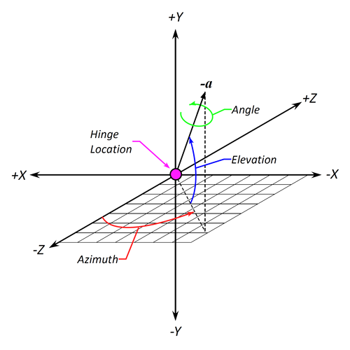
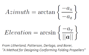
The Azimuth and Elevation may be calculated from known Cartesian components of the rotation vector a.
The positive folding direction is indicated by the circle and arrow about the folding axis.
Propeller Caps and Tessellation
The root and tip cap types may be altered under the More tab in the propeller component window. With these settings, you can alter the shape of the cap between flat, rounded, sharp, or none as well as the additional extended-edge cap types and also adjust the tessellation or number of interpolated lines on the cap. Similar to other caps, if you find that the root or tip cap is too sharply turning at the leading or trailing edges you can activate the Sweep Stretch button which will loft those caps a bit more and smooth the transition.
The overall tessellation of your propeller is set using the Num U and Num W parameters under the Gen tab where a larger number of points in the radial or chordwise directions will generally decrease any faceting of the blade surface. The clustering or grouping of these lines may be adjusted under the More tab where the leading edge, trailing edge, root, and tip clustering are located. Values less than 1.0 group the lines closer together in the region and values greater than 1.0 space them further apart. A value of 1.0 implies uniform or unit strength at that location. For uniform distribution, set both ends of the blade (either LE/TE or root/tip) to 1.0.
You may need to increase the radial (U) tessellation to properly capture the blade profile for export or analysis. Don't go overboard, though.