OpenVSP Bodies of Revolution
Although apparently simple at face value, the Body of Revolution component is remarkably complex underneath and enables a wide variety of axisymmetric designs based upon a few parameters and the desired cross-section.

Introduction
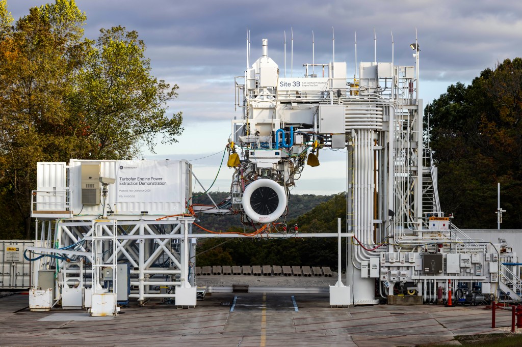
The Body of Revolution (BoR) component is very handy when you want to make an axisymmetric shape based on a single cross-section. Some examples include engine nacelles, complex tanks or stores, or even unconventional shapes like a candlestick or football. Note that by definition, you may not ‘squash’ this component to make an antisymmetric body. This component is purely axisymmetric similar to a “Revolve” CAD operation.
Surface Sections and Direction
The Body of Revolution component is effectively a wing-type body that is under a loop design mode where the first and last section are coincident and the surfaces are all symmetric about the centerline axis. Similar to a wing component, the U parameter follows the ‘root’ or start of the cross-section location and goes about the center axis along the surface. For hollow BoR geometries, the W location follows the convention of first marching along the inside of the part toward the leading edge and then along the outside of the part toward the trailing edge. Otherwise, when setting Upper or Lower design policy, the W location marches from the trailing edge (aft) to the leading edge (forward).
Design Parameters
There are relatively few design parameters for the Body of Revolution component, at least those generalized for the axisymmetric shape. These design parameters are only available in Flowthrough design mode. Diameter sets the diameter of the controlling leading edge feature line wrapped around the center axis. Note that even if you modify the leading edge closure, the Diameter is still calculated on the original, unmodified W reference location. If you skew upper, it will use the inner curve. If you skew lower, it will use the outer curve. If you skew both, it will use the middle curve.
The Angle parameter sets the angle between a straight line from the fixed leading edge and trailing edge and the centerline where a positive angle moves the trailing edge inward and a negative angle moves the trailing edge outward. Again, if you choose to modify the trailing edge closure, the original, unmodified reference edge is used for Angle.
Design Mode
The Body of Revolution Design Mode enables you to choose which section of the cross-section profile you wish to rotate. You may use the Flowthrough option which will use the entire cross-section and revolve it based on Diameter and Angle. You may also use Upper which only uses the upper (0.5 <= W <= 1.0) part of the cross-section curve or Lower which uses the lower part of the curve (0.0 <= W <= 0.5).
Cross-Sections
Cross-sections in a Body of Revolution define the profile that is rotated about the centerline axis. These settings will also determine the length of your component as well as other features such as thickness, camber, or height depending on the section type. For example, an airfoil cross-section will use chord to define the length (front to back) of the revolved body and the Camber or T/C will define the shape of the section. However, an ellipse will use Width to determine the length of the body and Height will determine the thickness.


