


![Request for Information – Potential [Placeholder for Prize]](https://assets.science.nasa.gov/dynamicimage/assets/science/psd/solar/2023/09/s/solarsystem_0.jpg?w=1024)


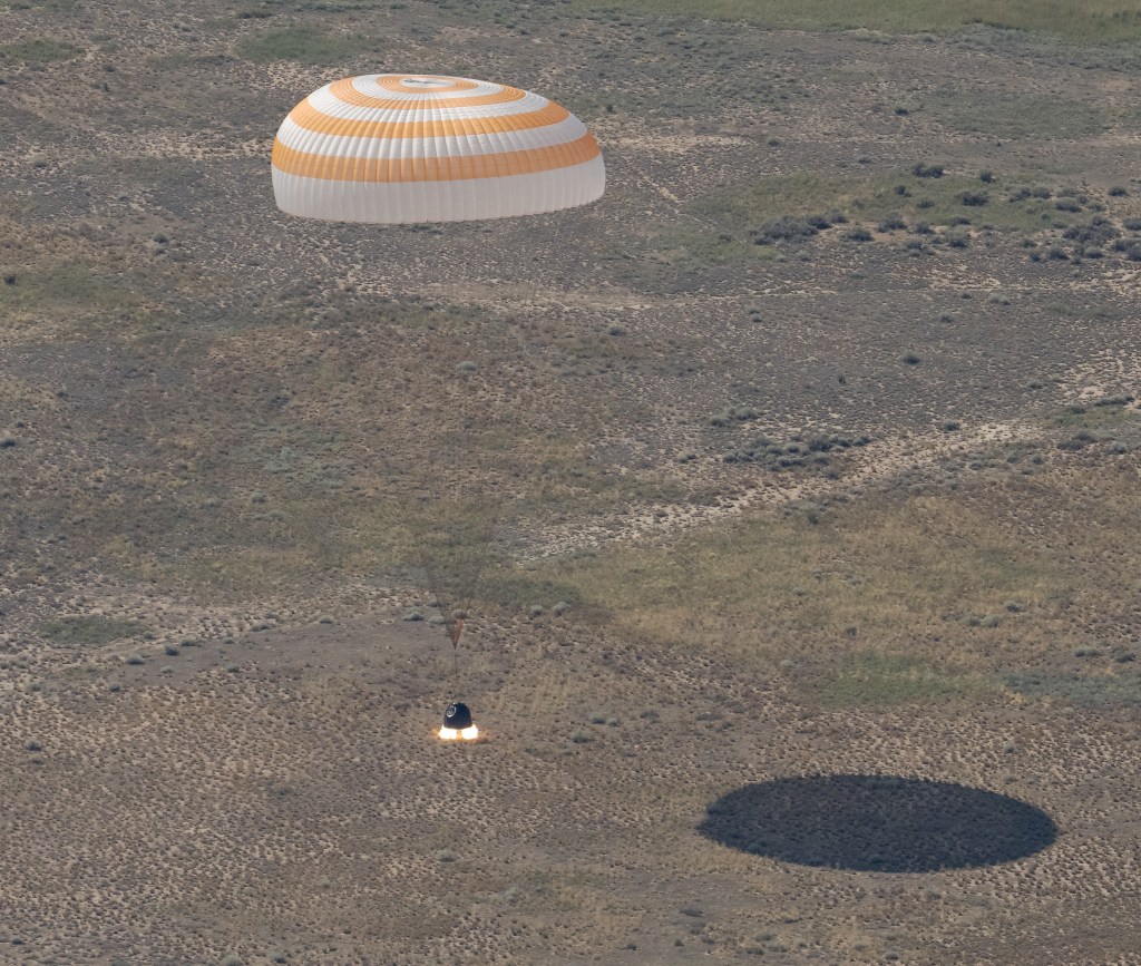
Sine Vibration testing replicates the low-frequency launch environment and is used mainly on flight articles to determine if they can survive the harsh launch environment. Testing involves accepting calculated risk, but failure to follow best practices for sine vibration testing has resulted in avoidable damage to flight hardware. Dr. Curtis Larsen, NASA Technical Fellow for Loads and Dynamics and Mr. Daniel Kaufman, NESC Discipline Deputy for Loads and Dynamics and their Technical Discipline Team identified top risks and documented best practices to help mitigate those risks and take full advantage of what sine vibration testing has to offer. This information is succinctly summarized in NESC Technical Bulletin 15-03. An expanded version of Technical Bulletin 15-03 appears below.
Sine Vibration Testing Summary
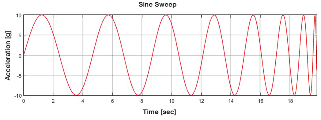
Sine Vibration (SV) Testing involves subjecting the test article to a swept sine input over a frequency range (typically 5-100 Hz) intended to replicate the low-frequency launch environment. This test method is used for various purposes on a structural model but mainly on flight articles. The SV levels are derived from measured flight data or based on interface acceleration levels from coupled loads analysis (CLA). A logarithmic sweep rate is typically used to excite a constant time interval per bandwidth for the test, (e.g., 2 or 4 octave/min), which is intended to simulate sustained sine and transient events that occur during launch. Risks can be mitigated through best practices.
Background and Objectives of Sine Vibration Testing
This test has been used for decades on space flight hardware to meet the following test objectives:
- To qualify secondary structures and/or hardware that have redundant mounting interfaces or are difficult to model/analyze;
- To dynamically qualify hardware that may respond to the low-frequency launch environment but may be difficult to test at lower levels of assembly such as cable harnesses and plumbing lines;
- To demonstrate operation of critical mechanisms after exposure to the dynamic launch environment such as a low- frequency workmanship screening;
- To demonstrate that minimum frequency requirements are met;
- To obtain dynamic response information, such as frequency response functions, suitable for correlating certain structural modes (mini-modal survey); and
- To identify damping and nonlinear behavior at flight-like load levels.
Sine vibration testing is required by NASA-STD-7002 and most launch vehicle organizations as a final dynamic qualification of the payload to demonstrate acceptability for flight. NASA requirements differ however between the SV testing requirements provided in Air Force Standard SMC-S-0162, Test Requirements for Launch, Upper-Stage and Space Vehicles, SMC-S-0162 does not have a requirement for base shake testing of fully integrated spacecraft. The European Space Agency (ESA) requires SV in its Space Engineering Testing Standard ECSS-E-ST-10-03C. There is a significant difference in the way the notching criteria is accepted between NASA and ESA at the system level.
Sine Vibration Testing Risks
The SV testing method has been used extensively. A few test incidents and mishaps have occurred associated with the risk of testing an article through resonance. The following is a list of identified risks:
- Testing in a frequency range beyond the CLA validity or cut-off frequency, or beyond the range to which the model has been test correlated.
- Lack of definition of test abort settings criteria and workable margin between limit and abort levels.
- Depending on the facility, a hard shutdown can happen either due to loss of electrical power and/or exceeding amplifier capability. A soft shutdown is always preferable but sometimes not available.
- Lack of sufficient pre-test analysis.
- Non-linear response in the structure. This can be mitigated by starting at lower levels and adjusting the input to achieve the desired response.
- Lack of sufficient instrumentation to adequately monitor hardware responses and protect from over-test.
- Unpredicted interactions between the shaker and test article.
- Incorrect software version in the drive controller.
Best Practices for Sine Vibration Testing
Even though the SV test has benefited the industry, organizations should be aware of the above-mentioned risks and mitigate them in the planning and execution phases.
- Perform sufficient pre-test analysis to determine instrumentation locations and response limits, which can be used to protect the hardware from over-test.
- Prior to running a full-level test, lower levels of input with proportional limits should be run to verify the behavior of the test article and control system. After completion of each low-level run, the response should be compared with analysis predictions and prior runs to verify that the test article is behaving as expected.
- Given the fact that the structural response in this test is through resonance, the limit and abort levels need to be properly defined.
- Clearly define and implement response abort levels for which positive margin of safety can be demonstrated for the hardware.
- Do not test beyond the model correlation frequency range and/or the CLA range as margins cannot be relied upon because responses in that range are not available.
- Even if the test item is expected to have rigid body behavior in the test, define and implement response aborts. This is to prevent frequency shifts and unexpected resonance build-up and to prevent the unexpected.
- Check and compare at least once at the beginning of the test the unfiltered or raw time histories and the controller spectra. Expect some differences and adjust accordingly, mainly in regards to response limits and aborts.
- Consider non proportional limits at the lower levels of excitation to allow for additional response to understand lightly damped responses; use proportional limits from there onwards to verify controller performance. Limits should be in-place to protect the hardware regardless of the input level.
- Define in advance and discuss with the test engineers the control strategy that best suits the objectives. This is related to average, weighted average, or extemal control use.
In conclusion, SV is an effective test method at the disposal of flight projects to meet the defined objectives, but the risks should be addressed before and during execution to make it safe.
References
- National Aeronautics and Space Administration, Payload Test Requirements, NASA Technical Standard NASA-STD-7002, September 10, 2004
- Air Force Space Command Space and Missile Systems Center Standard, Test Requirements for Launch, Upper-Stage and Space Vehicles, SMC Standard SMC-S-016, 5 September 2014.
- ESA European Cooperation for Space Standardization Space engineering Testing, ECSS-E-ST-10-03C, 1 June 2012