


Quick Facts
Year Built: 1945
Historic Eligibility: National Register Eligible
Year Demolished: 2011
History
Throughout its history, the research conducted in Building 1234 was managed and conducted by the staff of the 16-Foot Transonic Tunnel.
After World War II, the quest for high-speed flight led to the development of high-subsonic and supersonic wind tunnels at Langley. However, tunnel test-section wall effects that contaminated aerodynamic data at and near Mach 1 posed a severe constraint on the state of the art for transonic design methods.
Researchers conceived and evaluated several radical approaches to obtain valid transonic data, including the famous slotted-wall concept which ultimately provided the breakthrough capability now recognized as one of the most important contributions of the Langley Research Center to aeronautics.
Other less successful concepts were also pursued, such as the Langley Annular Transonic Tunnel (ATT).
Annular Transonic Tunnel
The ATT was an extension of the “whirling-arm” concept which used models – mounted at the end of a rapidly rotating arm or support apparatus – to generate the desired test velocity. First proposed in 1944 as a potential approach to transonic aerodynamic testing at Langley, the ATT used a 57-inch rotating disc that was driven by two 200-horsepower motors at speeds up to about 4,300 rpm.
The annular characteristic of the ATT was related to two concentric cylinders that formed the inner and outer walls of the apparatus. A 3-inch spacing between the inner and outer cylinders was used as the test section for tests of airfoil shapes. As the airfoil model traversed in rotation, a low-speed axial flow was created through the annular test section by a blower to reduce wake effects and vary the angle of attack of the test article. Thus, the airfoil being tested experienced flow in a channel of infinite depth, and the dreaded “choking” phenomenon of conventional transonic tunnels at that time would be avoided.
The operational speed of the ATT was from Mach 0.6 to Mach 1.01. Special problems associated with this test technique were successfully addressed by Langley staff including how to measure surface pressures on the rotating test airfoil.
The technology involved in the ATT was closely associated with research efforts being conducted by the group in charge of the Langley 16-Foot Transonic Tunnel and the design, development and operation of the facility was accomplished in that organization.
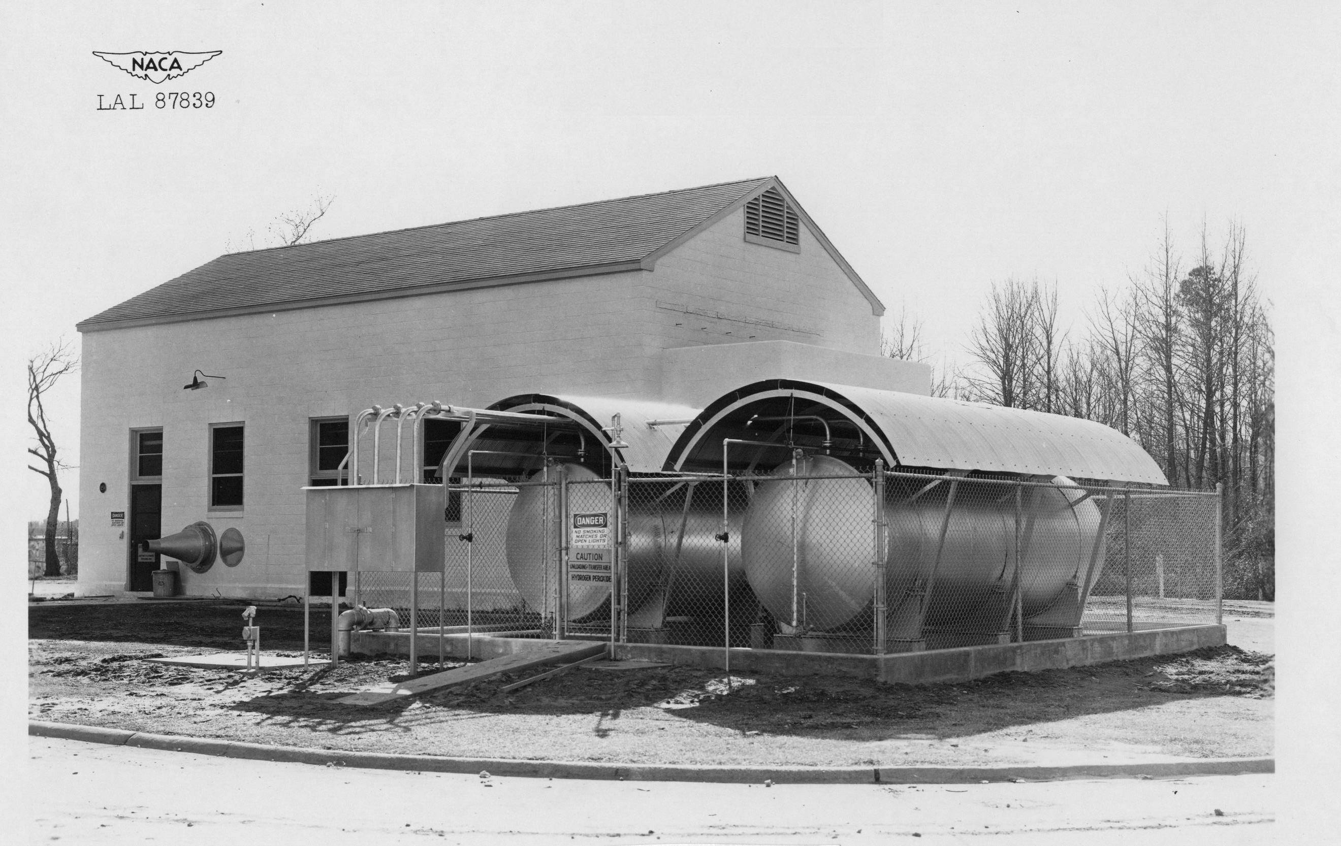
The facility was housed in a special cinder-block building (Building 1234) near the 16-foot tunnel and became operational in 1947. The ATT became noteworthy that year when the first pressure distributions ever measured on airfoil at precisely Mach 1 were obtained.
Testing of several airfoil types continued over a five-year period, but the testing procedure was extremely slow (only five models tested in five years) and pressure data acquired in the facility were consistently different from those measured in flight and other successful transonic wind tunnels. When the revolutionary slotted-wall transonic tunnel concept was demonstrated at Langley in the early 1950s, the ATT could no longer be justified and it was dismantled.
A remarkable admission of deception concerning the ATT was made by the NACA in 1954 when it was admitted that a wide-spread publicity campaign by Langley management in 1949 on the promise of the ATT concept was intentionally conducted to divert the world’s attention from Langley’s pioneering efforts on the slotted-wall concept.
16- By 24-Inch Water Tunnel
By the late 1970s, the building costs of wind tunnel models and the operating costs of large tunnel complexes made it necessary to develop less expensive testing methods. It was determined that a small water tunnel could be useful in basic research in 3D flow patterns.
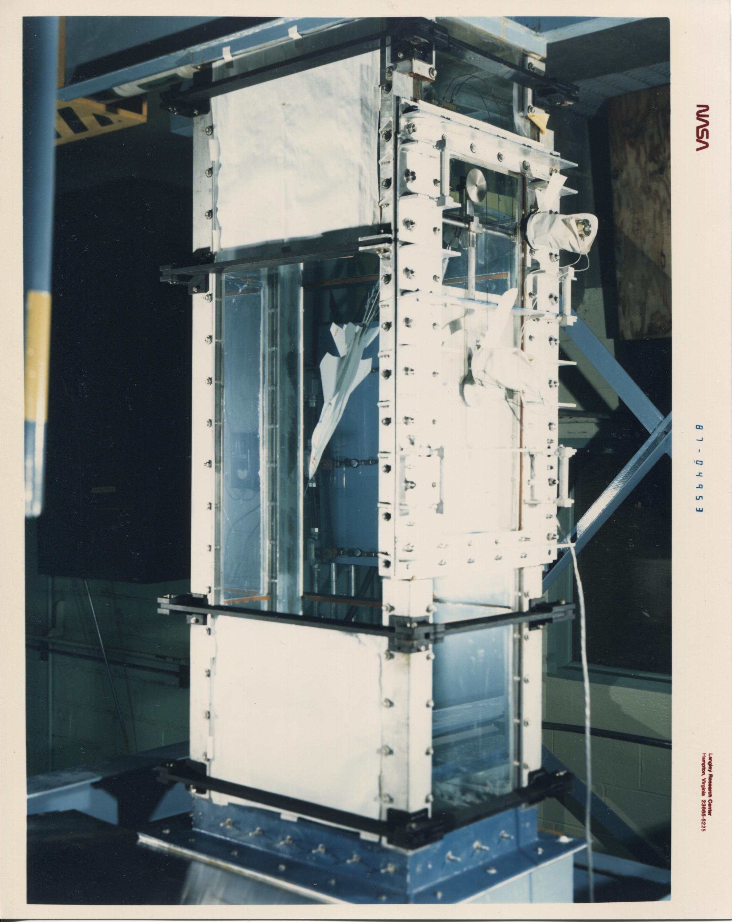
Room 100 of Building 1234 began operations as the 16- by 24-Inch Water Tunnel in June 1988. This was a closed return vertical tunnel with normal testing velocity of 0.25 feet per second, which was slow enough to easily observe flow phenomena. The model and sting could be rotated to obtain maximum deflection angle and the best view for observing the model. The test section of clear acrylic was located so the model was at eye level above the floor. Dyes injected in the stream provided a visual record of the flow patterns around models. Vortex flows were especially suited to the method.
Jet Exit Test Facility
Prior to being demolished, Building 1234 housed Langley’s Jet Exit Test Facility, a highly productive research apparatus used very successfully in the development of thrust-vectoring concepts. However, the bricked-over remnants of the concentric cylinder ends of the ATT could still be viewed within the building.
Jet Exit was a propulsion simulator test stand using room-temperature compressed air as the propellant (“fuel”). This type of testing was an early-stage screening tool for propulsion system components and a calibrator for wind-tunnel testing. The facility was used extensively (under contract agreement with Lockheed Martin) as a development and calibration facility for the Joint Strike Fighter STOVL propulsion nozzles. Test hardware was made by stereo lithography at NASA Langley.
Completed in 1945, the facility was an indoor ground test stand which combined multi-flow propulsion simulation with high-pressure and high-mass-flow capabilities. Two individually controlled 1800-psi air lines supplied the test model system(s) and provided flow rates up to 27 lbm per sec, per line.
Supply air was heated to maintain room-temperature conditions. The mass-flow rate of each airline was measured using a system of multiple critical venturi meters. Such systems allowed accurate mass-flow computations over a large range of flow rates and areas. Pressurized air from one or both supply lines was directed through a selected model interface system into the propulsion simulation geometry and vented to atmosphere in the large test bay area.
Two model support systems were available for testing. The dual-flow propulsion simulation system was the more complex test rig, designed for supply and control of two separate flow fields, a primary (core) flow and a secondary flow. It incorporated a six-component strain-gage force-and-moment balance with maximum axial force capacity of 1,200 lbf. The alternate test rig, which did not incorporate a balance system, was a simple plenum chamber that mixed high-pressure air from both sources to supply a single intake for larger scale models.
Typical facility instrumentation consisted of steady-state devices including the balance components, thermocouples, static pressure transducers and an electronically scanned pressure (ESP) system. The Unix-based data acquisition system could acquire up to 90 channels of analog data and several hundred ESP pressure measurements. Video monitoring and recording of the test area and model were available. Available non-intrusive flow-visualization techniques included shadowgraph density-gradient imaging and surface-oil or paint-flow imaging.
The Jet Exit Test Facility was originally designed for single-flow nozzle testing and played a significant role in the development of advanced aircraft thrust-vectoring nozzle concepts from 1970 to 1990. The facility was redesigned in the early 1990s to add a second independently controlled air system. Additional controls for low-volume flows were added during the late 1990s. The enhanced air systems provided quality flow control at rates from 1 lb/sec (or less) to 40 lb/sec.
Typical test projects in the years prior to the facility’s demolition included: performance evaluations of advanced exhaust systems; calibration of nozzles and scaled components such as mass-flow plugs for other applications; flow testing of full-scale fan-engine sectors for actuation evaluation; and performance testing of multiple-flow fluidic injection concepts (with core flow at high flow rates and two or more independently-controlled secondary flows at low flow rates) for thrust vectoring, plume control or throat-area control.
The facility was abandoned and demolished in 2011.
Related Materials
Description of Annular Transonic Tunnel
Isometric View of Water Tunnel
Sketch of Annular Transonic Tunnel
Examples of the kind of work done in this facility can be found on the NASA Technical Reports Server. Examples include: