


For more than two decades, sine burst testing has provided a method of strength testing for aerospace hardware that not only minimizes potential for damage to the test item, but can be performed on the shaker along with other tests to maximize efficiency. But with all testing comes potential risk. Mr. Daniel Kaufman, NESC Discipline Deputy for Loads and Dynamics, identifies top risks, such as unintended over test or erroneous calculations, and provides best practices to help mitigate those risks and take full advantage of what sine burst testing provides. This work was published in NESC Technical Bulletin 15-02. An expanded version of Technical Bulletin 15-02 appears below.
Sine Burst Testing Summary
Sine Burst (SB) Testing is used for strength testing of aerospace hardware and is applicable to structural testing Agency-wide. It is an alternate to static pull and centrifuge tests. The main advantage is that it can be implemented while hardware is on a shaker for other tests such as random or sine sweep vibration. It also imposes a lower number of cycles compared with a sine dwell or sweep. The test is particularly suitable for relatively stiff components or electronics boxes, instruments, or spacecraft. However, there are risks involved since this test is performed with the shaker control in an open loop mode. These Identified risks can be mitigated by best practices.
Background of Sine Burst Testing
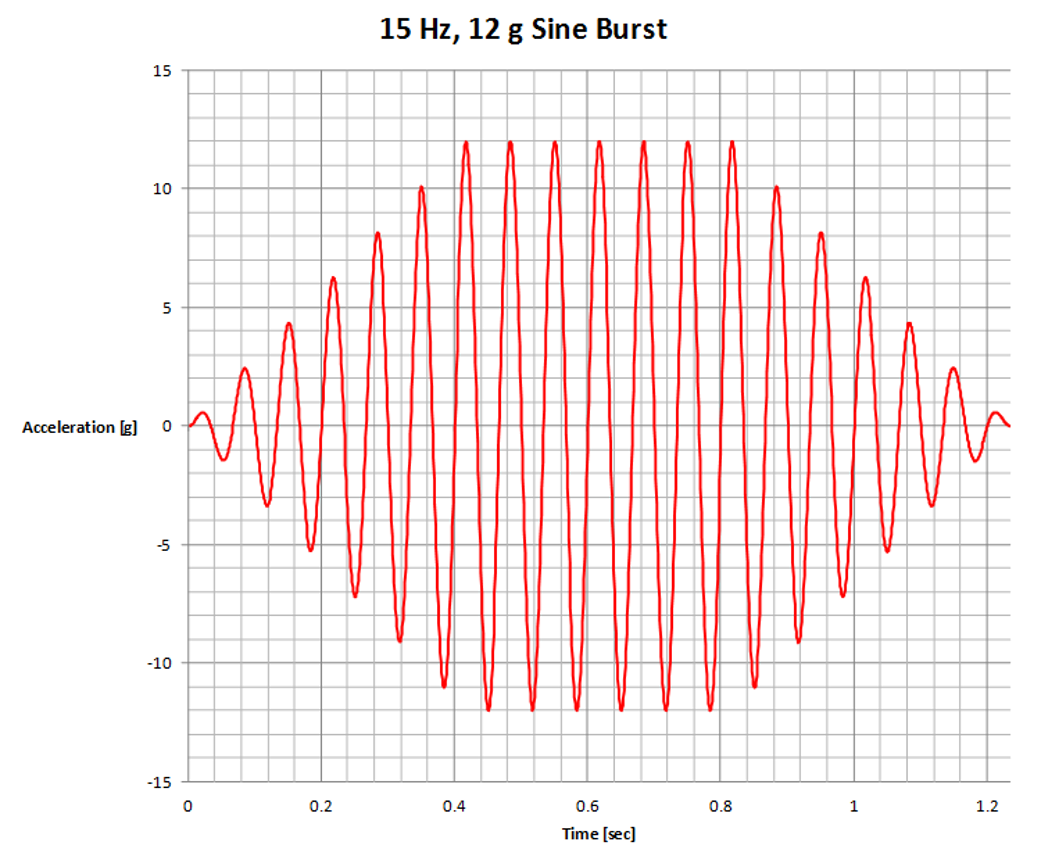
In the late 1980’s, the SB method was used at Goddard Space Flight Center as a means to impart a static load into a component, instrument, or relatively small/stiff spacecraft. Sine burst testing was originally developed as a method for applying structural loads to the Far Infrared Absolute Spectrophotometer and the Diffuse Infrared Background Experiment – two scientific instruments flown on the onboard the Cosmic Background Explorer mission. The shaker controller is used to apply an enveloped sinusoidal base drive acceleration to the test item at a fixed frequency with 5-10 cycles at peak level as shown in the figure. The test frequency is such that the item response would be pre-resonant or as close as possible to the rigid body response, usually being no more than 1/3 of the first mode frequency of the test article. The lower frequency limit would be 0.8 times the shaker stroke, as impacting the hard stops would be undesirable. Because the test article is being accelerated as a rigid body, a uniform inertial body load is generated in the test article.
Limitations of Sine Burst Testing
To achieve the target stresses in some areas of the hardware, an over-test may need to be imparted in other areas. Therefore, this method requires pre-test analysis to verify that the stress targets can be achieved within acceptable levels of over-test. Another limitation is that if the required load case is unidirectional (say compression), there will inevitably be a reversal load (tension) imparted on the article or vice-versa. The test is a single axis test so different orientations of the test article may be required to achieve strength qualification. The method offers the advantage to trade test article accelerations for mass in order to achieve a target net center of gravity (CG) acceleration. Force gages complement this test very well when the test target is the net CG acceleration. There is a need to monitor the test article for any unexpected dynamic amplification especially if the applied frequency does not meet the 1/3 of natural frequency guideline.
Sine Burst Testing Risks
The SB method has been used extensively since its inception, however it has not been free of test incidents. The following is a list of identified risks:
- Impacting the shaker stops by exceeding the shaker maximum displacement or stroke: Typically, shakers have a soft shut down (SSD) switch at a percentage of the maximum stroke to protect the shaker, test article, and personnel.
- Shaker stiction: The controller computes a linear transfer function of acceleration to update the drive for the next level. If the shaker has any stiction (non-linear behavior) at the targeted test levels, the updated drive may be higher than required and impart an unintended over-test.
- Unintended system operation: An unintended operator action or controller setting drives the amplifier to an over-test.
- Drive signal adjustments: If the test procedure is such that intermediate levels require engineering adjustments to the drive signal, the risk is of a wrong calculation of this adjustment and would lead to an unintended over-test.
- Lack of independent test over-protection system: This is addressed by using an accelerometer triggering an independent SSD if a certain acceleration abort or threshold is reached. If the response of the over-protection system is fast enough and the test article has positive margin for the amount of over-test, this is a definitive solution, otherwise it only mitigates a failure.
Best Practices for Sine Burst Testing
While the SB method has benefited the industry, organizations should be aware of the aforementioned known risks and mitigate them in the planning and execution phases of this test through these best practices:
- Given the impulsive nature of this test, do not count on the shaker displacement SSD and set a proper SB frequency high enough not to exceed the displacement that triggers the SSD.
- Any intermediate drive adjustments made by engineering personnel should be independently checked and the test sequence should be restarted from the lower levels.
- Avoid using the method at high levels of assembly or on a complete flight unit. The preference is to use the method with engineering test units which usually comprise the structure under test with mass simulators for the remaining hardware.
- Develop metrics for routinely assessing the mechanical “health” of the shaker and slip table systems.
- Evaluate the drive signal magnitude and the coherence function estimate between the drive and control accelerometer prior to test continuation. Coherence in the frequency band close to the SB frequency should not be lower than 0.9.
- Perform a facility checkout with a mass mockup prior to mounting a piece of critical hardware and compare recorded drive signal voltages at each level during the actual test. Engage in technical interchange meetings for planning prior to test execution between the analysts, the test engineers, and operators.
- Take time to review and make sense of the time history acceleration and or force data collected after each test run. This is essential to have available as well as the controller drive voltage and amplifier output time histories.
- Reconsider testing via SB any hardware that is inherently non-linear, unless the non-linear nature is understood and accounted for in the pre-test analysis and procedure.
- If any of the risk mitigations fail or a new flaw is discovered, the final defense line resides in the use of an independent over-test protection system along with hardware positive margin of safety for the abort setting.
In conclusion, the SB has proven to be an efficient test at the disposal of flight projects, but the risks should be considered along with the benefits to make it safe and effective.
References
- NASA Report on High Solar Energy Solar Spectroscopic Imager (HESSI) Test Mishap, (Washington, D.C.: NASA Headquarters, Code S, May, 2000)
- LADEE Spacecraft, Type C Mishap, IRIS Case Number: S–2012–124–00008