


![Request for Information – Potential [Placeholder for Prize]](https://assets.science.nasa.gov/dynamicimage/assets/science/missions/a-step/FFR_Earth_Background_20251120%20.png?w=1024)


Armstrong conducts innovative flight research that continues to expand its world-class capabilities, with special expertise in research and testbed platforms, science platforms, and support aircraft. Researchers place particular emphasis on providing accurate flight data for research aimed at designing next-generation flight vehicles.
Described here are research projects that are seeking to increase safety, reduce costs, and dramatically decrease testing and approval times.
Pilot Safety Effort
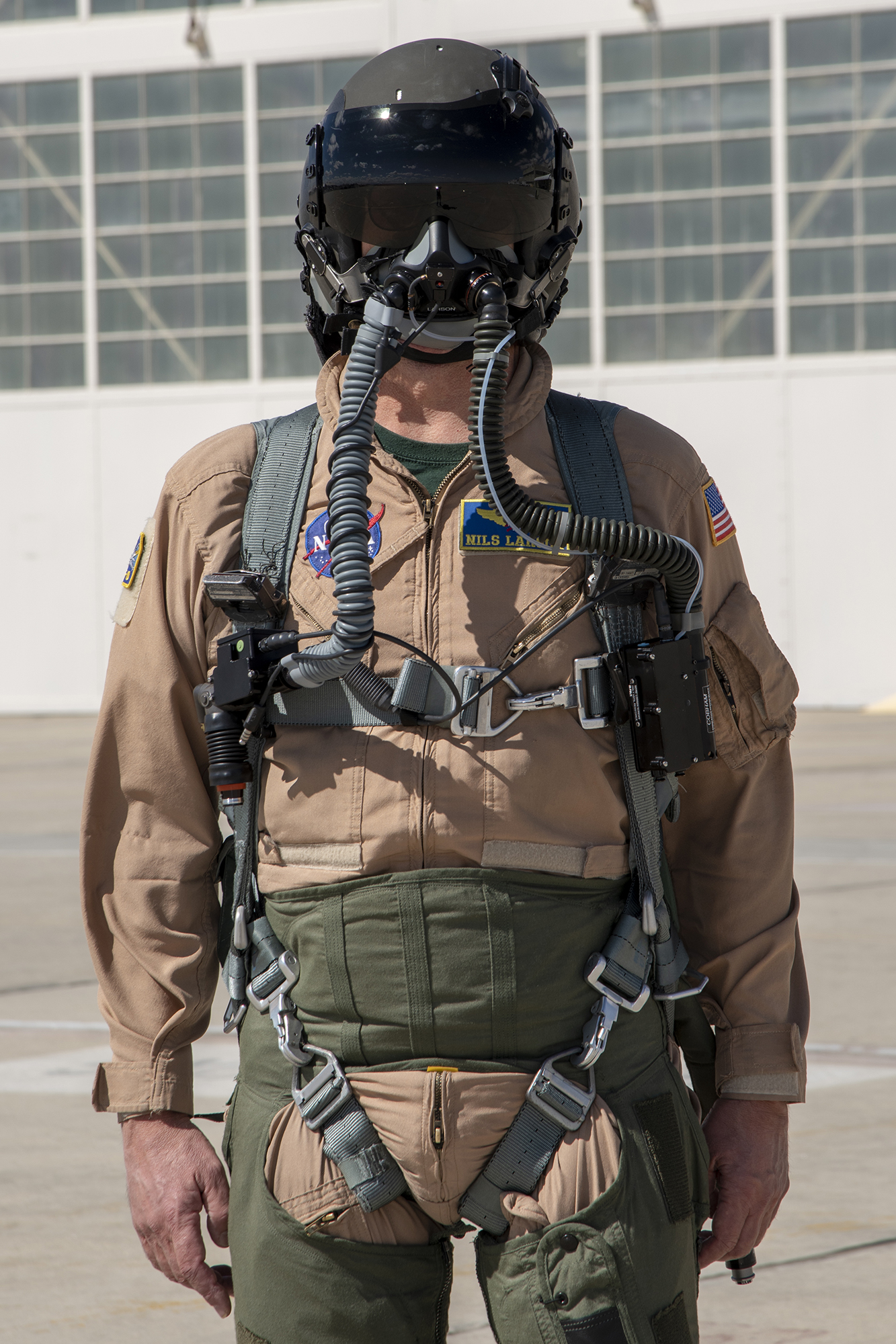
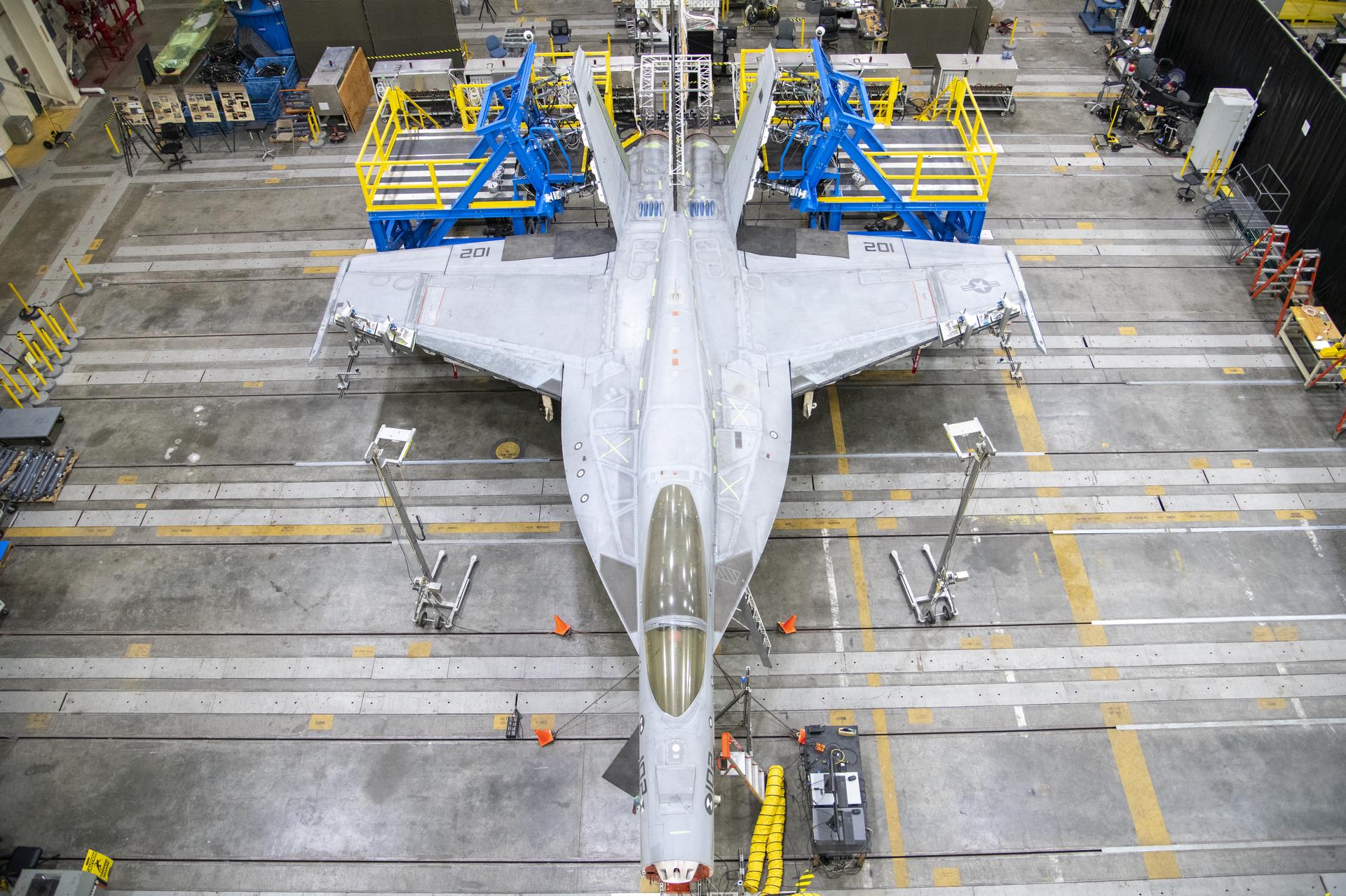
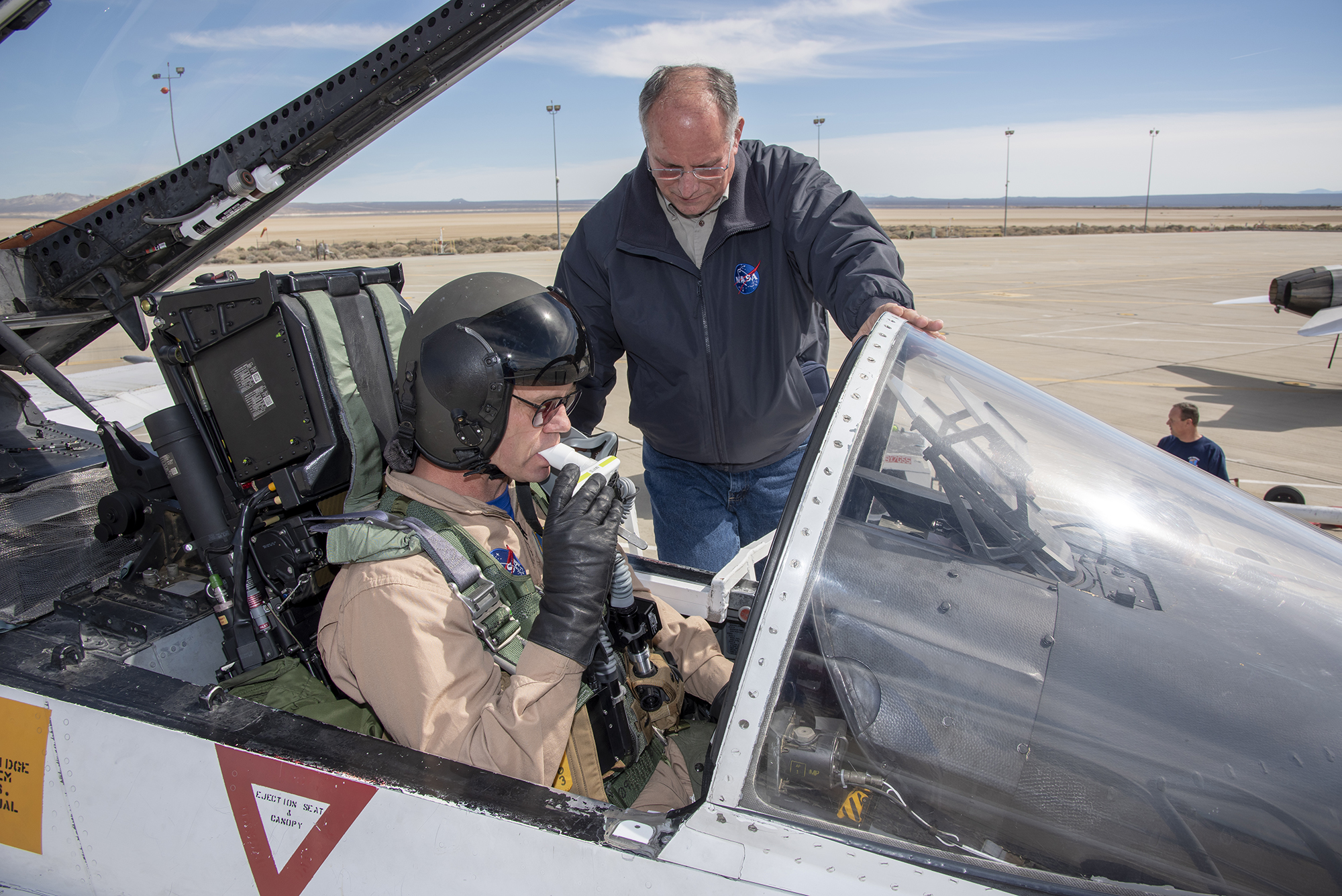
Armstrong researchers are contributing to a NASA effort to increase pilot safety. The Pilot Breathing Assessment (PBA) program is working to better understand how flight conditions may cause pilots to experience potential life-threatening physiological episodes (PEs) resulting in cognitive impairments, numbness, tingling, lightheadedness, behavioral changes, and fatigue. The NASA Engineering and Safety Center (NESC) tapped Armstrong to conduct the PBA flights to leverage the center’s F/A-18A/B and F-15D aircraft, which are equipped with oxygen systems used on modern military aircraft. Past research has focused on studying aircraft to reduce PEs. NESC is now working to understand pilot response to various flight conditions. NASA will use the data gathered through PBA flights in the development of new oxygen masks and aircraft equipment systems.
Work to Date
At Armstrong, the effort involved five pilots, four aircraft, two aircrew equipment configurations, and approximately 90 hours of flight. Pilots flew scripted profiles representing a variety of conditions experienced throughout the aircraft operating envelope, including high-altitude flights at 40,000 to 50,000 feet; aerobatic flights; a combination of loops, rolls and dives, also known as a squirrel cage flight; and low-altitude flights through canyons.
Looking Ahead
NESC will study the data set from each flight to compare data among pilots, flights, configurations, and aircraft performance, looking for patterns or unexpected results that may help researchers understand the causes of PEs. Planning is underway for an additional 50 flight hours of study and assessment.
Benefits
- Improves pilot safety: Extends understanding of physiologic responses to various flight conditions
Applications
- Military and research aircraft
- Spacecraft
PI: Lance Richards | 661-276-3562 | Lance.Richards-1@nasa.gov
Lightweight Antenna
A cross-center collaboration has yielded a novel lightweight antenna designed to boost aircraft and antenna performance. Fabricated with aerogels—which consist of 90 percent air—the conformal antenna is intended for beyond line-of-sight communications on small- to medium-scale unmanned aerial systems (UAS). A phased array chipset reduces radio interference to ground stations to address concerns related to UAS being integrated into the National Airspace System.
This multi-center effort was conducted under the Conformal Lightweight Antenna Structures for Aeronautical Communications Technologies (CLAS-ACT) activity within the Convergent Aeronautics Solutions project.
Work to Date
At Armstrong, integration tests involved a newly developed robotic antenna scanner for extended preflight evaluation and verification. These tests measured the antenna’s pattern characteristics to determine the feasibility of interference-mitigation techniques. The team then performed five flight tests with the antenna installed on the luggage door of a T-34C aircraft. The tests included four antenna configurations within a variety of flight altitudes and demonstrated the ability of the phased array to lower side lobes (i.e., unintentional radiation from the antenna) as the antenna delivered its signal to its intended target.
Collaborators
The antenna was designed and tested in the anechoic chamber at NASA’s Glenn Research Center. The on-aircraft modeling of the antenna’s performance happened at NASA’s Langley Research Center. The preflight planning was accomplished at NASA’s Ames Research Center.
Benefits
- Fabricated with aerogels: The antenna is thin and flexible and offers improved gain, bandwidth, and efficiency.
- Aerodynamic: The antenna’s design minimizes drag for better fuel efficiency, whereas conventional satellite dishes are heavy, bulky, and require a gimbal to maneuver and point toward communication satellites.
Applications
- Small and medium UAS
PI: Patricia Ortiz | 661-276-3334 | Patricia.Ortiz@nasa.gov
In-Flight Temperature Measurements
Armstrong researchers have demonstrated a compact and robust prototype pyrometer capable of measuring aircraft surface temperatures and emissivity. Pyrometers measure high temperatures by observing emitted radiation. However, aircraft vibrations can render unreliable pyrometer measurements during flight. This device employs a spectrometer with a digital light processor (DLP) to measure the intensity of multiple wavelengths in the near-infrared (0.9-1.7 micron) range.
Work to date
The invention uses existing components in a new way. Developed for use in televisions, the DLP technology is used here within a robust scanning array that is nearly impervious to vibration and requires a single detector, as opposed to more complex, multi-element array detectors. The result is a mechanically stable device that is the first use of a spectrometer of this type for temperature measurements.
Looking ahead
Further work will refine the device and seek to develop a ruggedized version that can be used for actual aircraft flight measurements.
Benefits
- Compact: Employs a single detector rather than the array of detectors often present in conventional pyrometers
- Robust: Can be mounted onto various aircraft to provide in-flight temperature measurements
- Highly accurate: Allows for increased control over wavelength measurement in the near-infrared range via a digital interface
Applications
- Avionics
- Space exploration
- Glass, metal processing, and ceramics industries
PI: Timothy Risch | 661-276-6720 | Timothy.K.Risch@nasa.gov
Airvolt Single Propulsor Test Stand
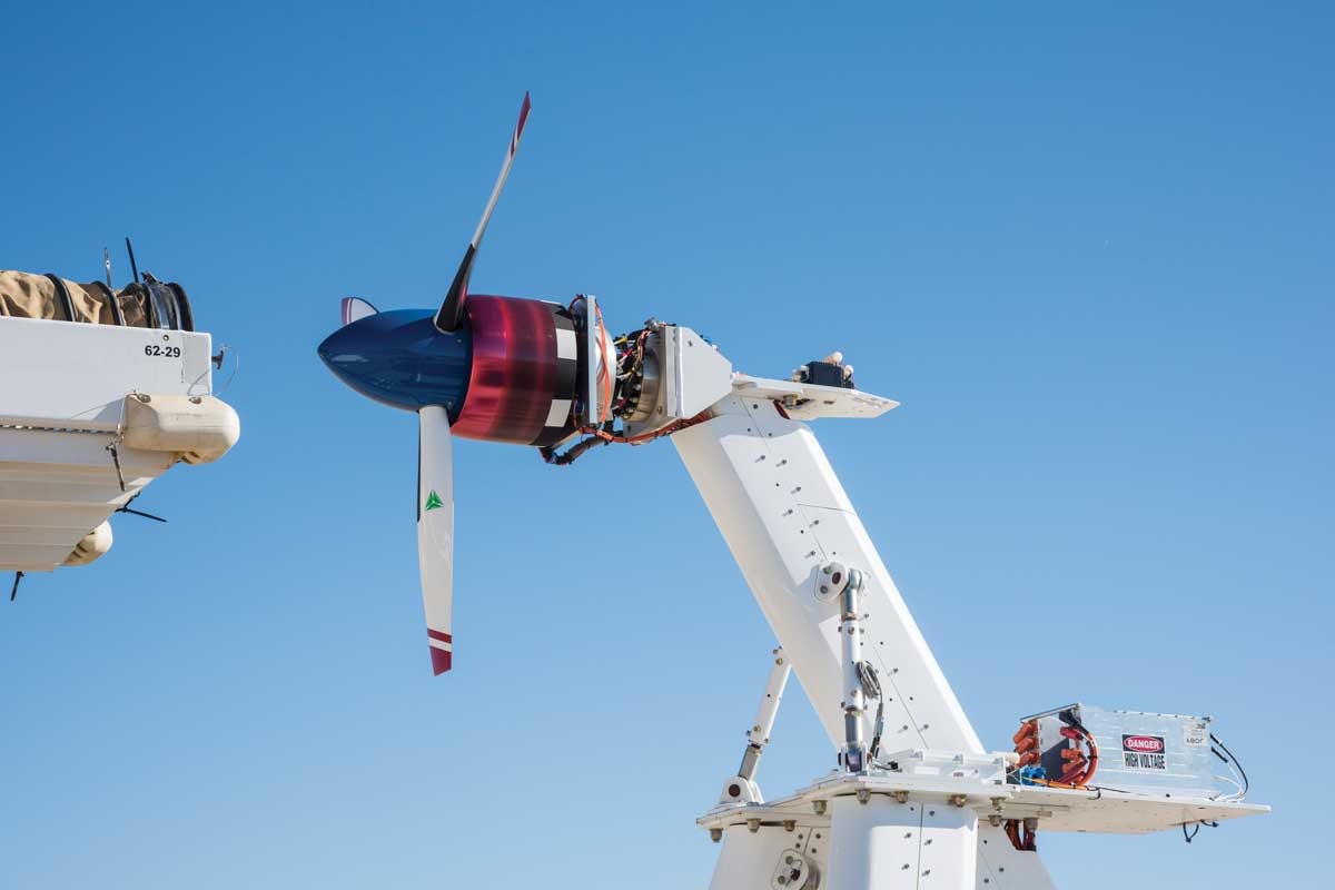
A modular test stand developed at Armstrong is helping researchers conduct extensive measurements for efficiency and performance of electric propulsion systems up to 100 kilowatts (kW) in scale. The Airvolt test stand enables evaluations of subsystem interactions as well as efficiencies of different batteries, motors, controllers, and propellers. The test stand offers opportunities to determine effective test techniques for electric propulsion innovations. Its large suite of sensors gathers extensive data on torque, thrust, motor speed, vibration/ acceleration, voltages and currents, temperatures, and more. The Airvolt test stand is allowing the aviation industry to test a wide range of electric propulsion systems to understand efficiencies and identify needed design improvements.
Work to date
The Airvolt test stand supported testing of the X-57 Maxwell experimental aircraft cruise motor and cruise motor controller. The X-57 aircraft will be used to demonstrate aerodynamic efficiency of an optimized distributed electric propulsion wing. The 30-kW propulsor system is under development and requires testing to demonstrate operational capability for endurance, command, and control. More than 80 hours of run time have been conducted. Airvolt testing enabled improvements to wiring, temperature sensor placement, command protocol, and motor tuning parameters. Other issues such as electro-magnetic interference of ground test sensors were also identified. The test operations also provided training for working around high-voltage systems.
Looking Ahead
The team will support other electric propulsion testing research, as needed.
Benefits
- Highly efficient: Offers high-speed sampling rates, up to 2.5 million samples per second per channel
- Modular: Allows researchers to test a variety of motors, controllers, and batteries as well as a wide range of parameters
- Flexible: Accommodates different motors, up to 100 kW, through the use of motor adapter plates
Applications
- Characterize new electric propulsion technologies
- Refine simulation models
- Develop best practices for testing procedures
PI: Yohan Lin | 661-276-3155 | yohan.lin-1@nasa.gov
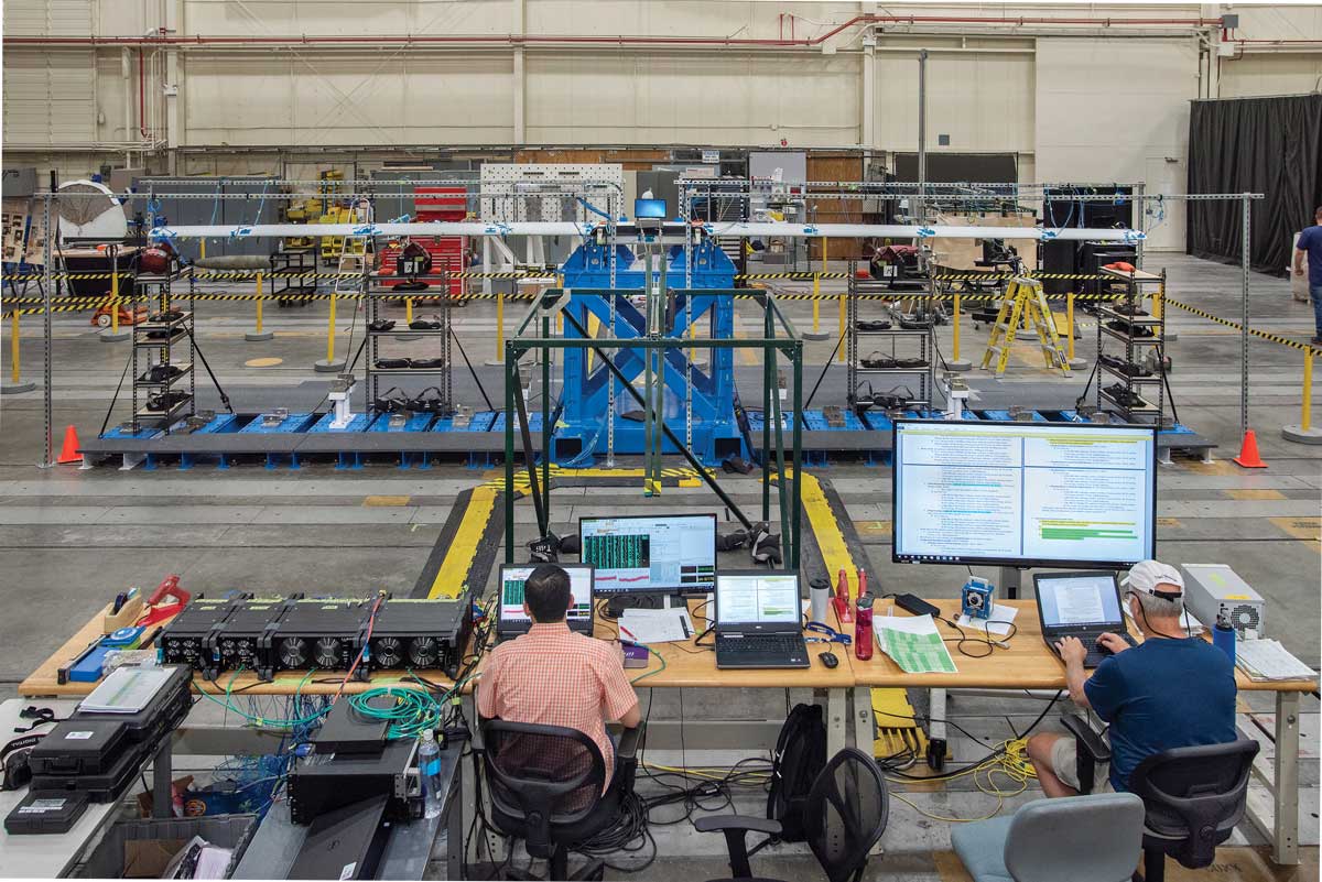
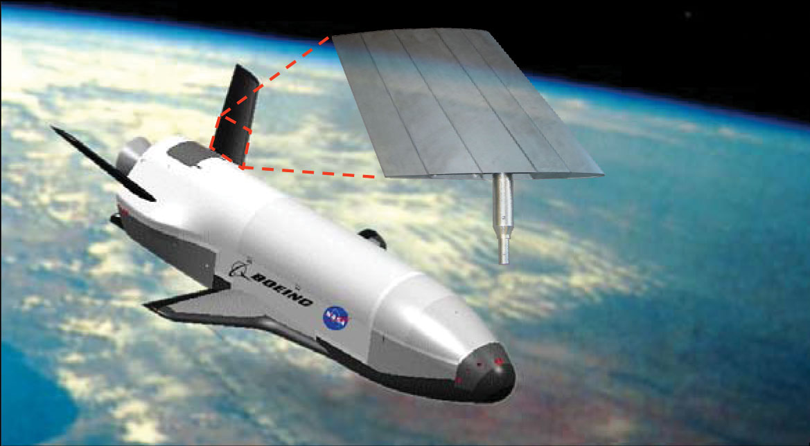
Store Separation
Future research at Armstrong will require analysis and test capabilities that enable safe and acceptable store separation. The goal of this research effort is to perform a store-release test in the Flight Loads Laboratory (FLL) and compare test data to analysis models. Displacements, velocities, accelerations, and loads will be recorded to compare with analysis models. The capabilities and techniques developed during this Center Innovation Fund project will help ensure that Armstrong has the analysis and testing capability to lead future innovations in the air launch and unmanned aerial system (UAS) store separation research communities.
Work to Date
Initial modeling and simulation have been completed. Researchers have assembled the test setup with instrumentation, designed and fabricated a fire control system, and documented test procedures and hazards. The next steps are to collect acceleration data using a six degree-of-freedom telemetry kit mounted in the fuse well of the nose of the test article, collect displacement data using high-speed video, and collect reaction load data between the store and the release hardware.
Looking Ahead
Testing is expected early in 2020.
Benefits
- Forward thinking: Expands Armstrong’s dynamic loading analysis and testing expertise
- Capability building: Extends FLL’s dynamic testing methods to support future store separation demonstrations
Applications
- Conventional store separation projects
- UAS/drone deployment and docking demonstrations
PI: Eric Miller | 661-276-7041 | Eric.J.Miller@nasa.gov
Fixed Base Correction Method
Armstrong and industry partner ATA Engineering are evaluating a modal testing technique to measure fixed base modes from a test article mounted to a dynamically active static test fixture. When mounted onto the wing loads text fixture, the boundary conditions of the Passive Aeroelastic Tailored (PAT) wing are not ideal for ground vibration testing (GVT) because the fixture is not rigid.
The Fixed Base Correction (FBC) method enables GVT for articles with non-ideal modal testing boundary conditions (e.g., load testing) that can complicate testing and increase costs and schedules. Because connection stiffness of boundary conditions greatly changes modal response, the FBC method employs multiple electromagnetic shakers simultaneously rather than the usual one or two shakers used in conventional GVT. The fixture excitation accelerations are used as references when calculating frequency response functions instead of traditional shaker forces. The FBC technique analytically removes and decouples the fixture response from the wing response to aid in comparing modal ground test results to finite element model results.
Work to Date
Researchers demonstrated in summer 2018 the feasibility of using the FBC method to successfully acquire decoupled wing modes.
Looking Ahead
The team is continuing to evaluate use of the FBC method for other aircraft applications.
Partner
ATA Engineering, Inc.
Benefits
- Enables valid testing: Allows for decoupled test article data from a test fixture
- Confirming: Enables comparison of test results to an analytical model
PIs: Natalie Spivey | 661-276-2790 | Natalie.D.Spivey@nasa.gov
Rachel Saltzman | 661-276-2906 | Rachel.Saltzman@nasa.gov
Soft-Support System
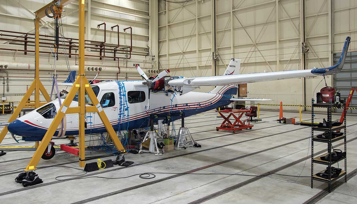
Armstrong researchers designed a bungee-based soft-support system and utilized it to simulate free-free boundary conditions similar to flight during ground vibration tests (GVTs) of the X-57 Maxwell electric propulsion experimental aircraft. As part of the required airworthiness process for developing the X-57, the GVTs will allow researchers to validate the structural finite element model for flutter and make any necessary updates. This soft-support system is planned for use on multiple GVTs during the X-57 aircraft’s development.
Work to Date
Researchers completed detailed characterization testing of the bungee rings and measured their isolation frequency (»1 Hz) and usable weight range (350 to 550 lbs per bungee ring). Testing demonstrated that the bungee rings have minimal creep elongation when under load for many hours. Test data were used to design the soft-support system, which was successfully used to conduct the X-57 Mod II aircraft GVT.
The bungee-based system used commercial-off-the-shelf bungee rings interfaced to standard aircraft ground support equipment to suspend the aircraft. The X-57 main landing gear axles served as the primary bungee lifting points, and a lifting strap placed around the nose gear bulkhead served as the forward bungee lift point. The system suspends the aircraft and allows it to bounce on the bungee rings, providing rigid body aircraft motion at very low frequencies. Using prescribed shaker excitation over wide frequency ranges, researchers measured the aircraft structural elastic modes. The soft-support system separates rigid body frequencies from the aircraft structural elastic modes of interest, enabling more accurate measurement of aircraft modal response and comparison of the GVT data to a free-free finite element modal analysis.
Looking Ahead
The soft-support system will be used with slightly different bungees to conduct the X-57 Mod III aircraft GVT.
Partner
ATA Engineering, Inc.
Benefits
- Adaptable: Allows for use of bungees for soft support of general aviation and similar aircraft, which often do not have overhead jacking points
- Effective: Provides clean aircraft modal test data for validating finite element models to support airworthiness certification and readies aircraft for future testing and development
PIs: Keerti Bhamidipati | 661-276-7305 | Keerti.K.Bhamidipati@nasa.gov
Rachel Saltzman | 661-276-2906 | Rachel.Saltzman@nasa.gov
X-57 Mod III Wing
Armstrong researchers completed ground vibration testing (GVT) on the wing that will be integrated into the final configuration of the X-57 Maxwell experimental aircraft. The goal of the Mod III GVT was to gather wing modal data in order to correlate fundamental wing modes with the finite element model (FEM) without any complicated wing structures, such as motor mounts, nacelles, or propellers. This data will help researchers understand the wing’s aeroelastic behavior. Early characterization of the basic Mod III wing structure will reduce programmatic risk that otherwise would have been added to future GVT, further complicating those tests and FEM update efforts.
Work to Date
In summer 2019, researchers successfully measured the desired Mod III wing frequencies, mode shapes, and damping. Specifically, two GVT configurations were completed:
- Clean wing with wingtip cruise nacelle mass simulators
- Clean wing only
Tests were performed with flaps stowed and fully deployed with ailerons locked and unlocked. A total of 192 test runs were completed that measured approximately 300 accelerometer responses.
Looking Ahead
Next steps are completing post-test data analysis, correlating the wing FEM to test data, and running a preliminary flutter analysis. There will be a Mod III full aircraft GVT prior to Mod III flights in 2021.
Benefits
- Reduces program risk: Component wing GVT enables analytical models to be correlated to test data earlier in the project life cycle.
PIs: Roger Truax | 661-276-2230 | Roger.A.Truax
Samson Truong | 661-276-2998 | Samson.S.Truong@nasa.gov
Natalie Spivey | 661-276-2790 | Natalie.D.Spivey@nasa.gov
Hot Ground Vibration Tests
Ground vibration tests or modal surveys are routinely conducted to support flutter analysis for subsonic and supersonic vehicles. However, vibration testing techniques for hypersonic vehicles are not as well established due to the thermoelastic interactions that can occur when high-temperature materials are incorporated into a hot structure that contains metallic components. In recent years, numerous high-temperature materials, new fabrication technologies, and sensors have been explored for hypersonic vehicle applications. A research team is working to develop a high-temperature modal survey to expand the research database for hypersonics and improve the understanding of such dual-material interactions.
Work to Date
Armstrong directed a program to test a carbon-silicon carbide (C/SiC) Ruddervator Subcomponent Test Article (RSTA) to support hypersonic material research. The RSTA has undergone numerous thermal, thermal-mechanical, and thermal-vibration tests. The team obtained good modal data at lower temperatures, but the off-the-shelf, high-temperature accelerometers malfunctioned on the hotter region of the test article. The experiments yielded test data that will be useful for future work and launched a high-temperature accelerometer development effort.
Looking Ahead
The research team has obtained custom-made and multiple other high-temperature accelerometers and is taking steps to understand, evaluate, and characterize their complexity and functionality in preparation for future thermoelastic vibration tests.
Benefits
- Innovative: Expands the research database for hypersonics
- Pioneering: Extends the understanding of the modal characteristic effects from high temperatures on hypersonic vehicles
- Aids research: Contributes to the understanding of flutter behavior at high temperatures
Applications
- Hypersonic vehicle research and design
Verification and Validation
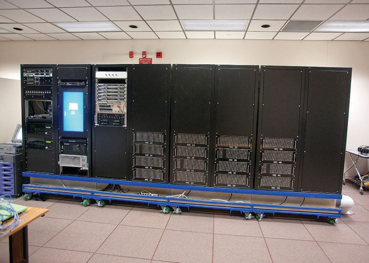
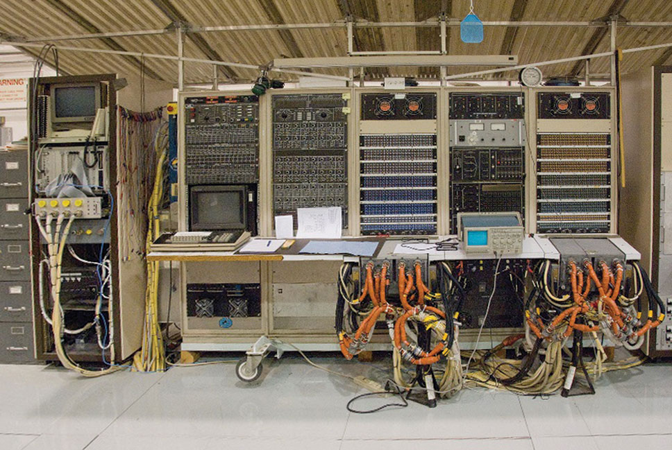
Armstrong engineers have developed a new simulation test bench for V&V of software and hardware for the F/A-18 aircraft. The new V&V test bench replaces a bench that was developed more than 30 years ago.
Work to Date
The new and more reliable bench is particularly innovative as it integrates reconfigurable software models for multiple aircraft components. These models enable high-fidelity simulations to be performed more easily and at significantly faster rates than were possible using the old hardware-centric test bench. In addition, this approach offers more accurate predictions of behavior.
Looking Ahead
The team plans to begin developing the capability to interface with a wide variety of other computers, which in turn will enable simulations of other aircraft such as the F-15 and systems with digital flight control systems.
Benefits
- Rapid data collection: Operates at faster rates, allowing for more detailed modeling
- Reconfigurable: Will accommodate other aircraft via software reconfigurations
- Economical: Reduces the number of expensive flight tests
Applications
- F/A-18 and F-15 aircraft
- Electric aircraft motors and actuators
- Control systems with redundant digital flight control systems