


![Request for Information – Potential [Placeholder for Prize]](https://assets.science.nasa.gov/dynamicimage/assets/science/psd/solar/2023/09/s/solarsystem_0.jpg?w=1024)


Ames Balance Calibration Taper Pin Installation to Balance Cables
By Richard Hanly, Instrument Engineer
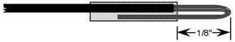
Taper Pin Type, Crimp and Insertion Tools
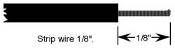
The following MUST be complied when attaching balance wires to taper pins. Most balance wires are extremely small (i.e. 30 AWG). Taper pins used in wind tunnels are not designated by the manufacturer for this size of wire.
The following is an acceptable alteration. NEVER solder wires to taper pins.
Very Small Wires, #26 AWG or Less:
Mechanical strength is important – Fold back wires (after stripping), cover with shrink tubing as shown.
Correct
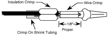
Put insulation all the way into rear crimp. For very small wires (#32, #36 AWG) two layers of shrink tubing may be necessary for proper crimp.
Incorrect
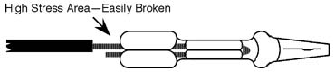
Do not let bare wire stick out beyond “rear” crimp. Wire is weaker without shrink tube.
The following is the accepted method for attaching designated wire size to the AMP P/N 41666 taper pin. NEVER solder wires to taper pins!
#22 and #24 AWG Wires:
Correct
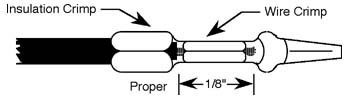
Proper taper pin crimp requires insulation be gripped by the “rear” crimp.
Incorrect

Do not let bare wire stick out beyond “rear” crimp.