


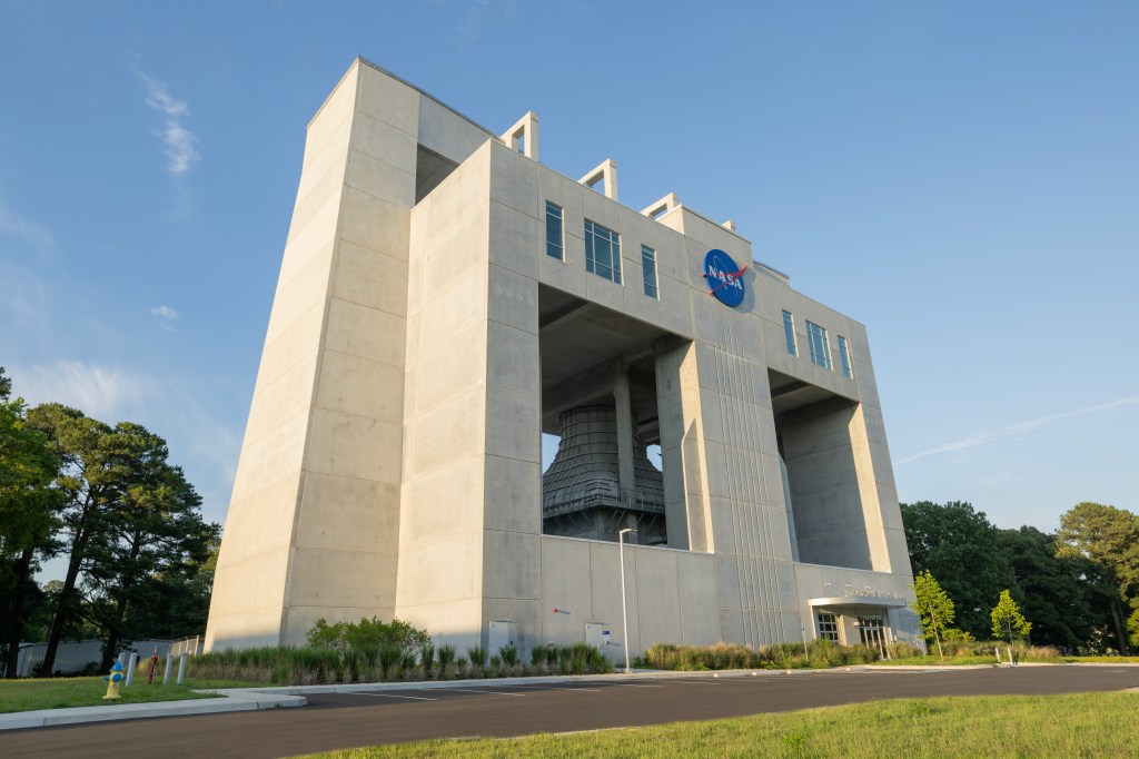


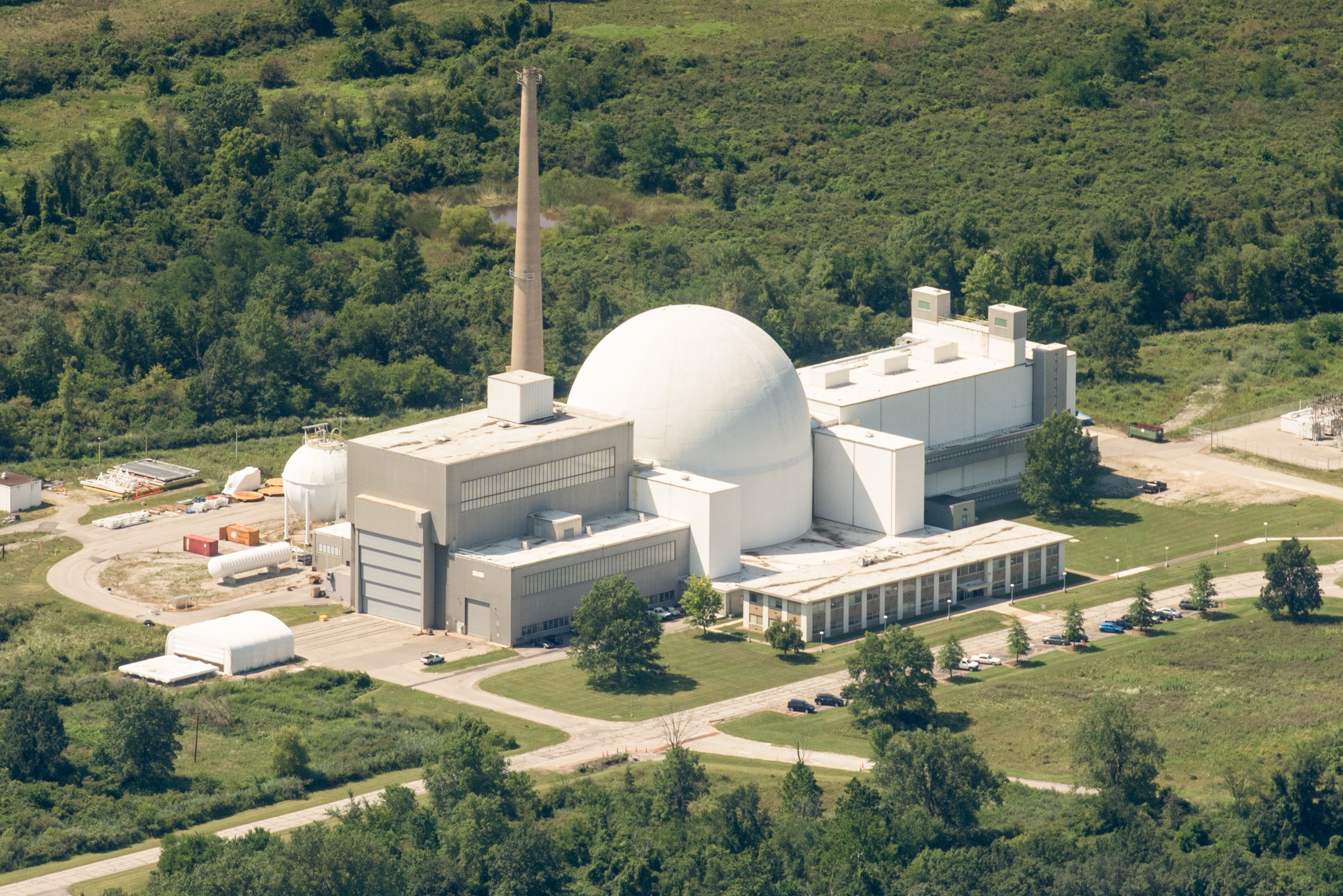
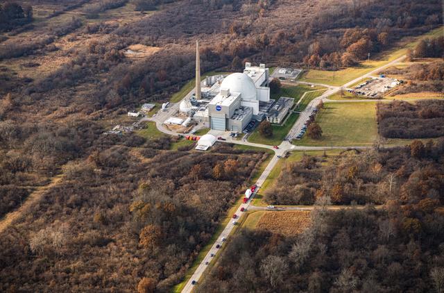
The Space Environments Complex (SEC) houses the world’s largest and most powerful space environment simulation facilities. The Space Simulation Vacuum Chamber is the world’s largest space simulation vacuum and EMI chamber, measuring 30.5 m (100 ft) in diameter by 37.2 m (122 ft) high. The Reverberant Acoustic Test Facility (RATF) is the world’s most powerful spacecraft acoustic test chamber, and the Mechanical Vibration Facility (MVF) is the world’s highest capacity and most powerful spacecraft sinusoidal base-shake vibration system. The SEC is located at NASA’s Neil Armstrong Test Facility in Sandusky, Ohio. This website provides information on the capabilities of this facility and the supporting infrastructure. The facility is available on a full-cost reimbursable basis to government, universities and the private sector.
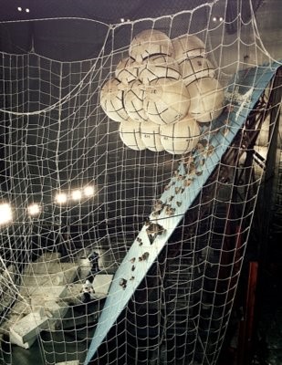
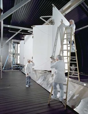
Gallery


Quick Facts
Space Environments Complex (SEC) – Overview
- Located at Neil Armstrong Test Facility (formerly Plum Brook Station), Sandusky, Ohio.
- Operated by NASA Glenn Research Center.
- Houses the world’s largest and most powerful space simulation facilities.
- Facilities are available to government, academic, and private sector users.
- Comprises four major testing capabilities:
- Space Simulation Vacuum Chamber (Space Power Facility – SPF)
- Reverberant Acoustic Test Facility (RATF)
- Mechanical Vibration Facility (MVF)
- EMI/EMC Test Facility
Space Simulation Vacuum Chamber (SPF)
- The Space Simulation Vacuum Chamber was designed to test nuclear and non-nuclear space hardware in a simulated low-Earth-orbit environment
- Largest vacuum chamber in the world:
- 30.5 m (100 ft) diameter, 37.2 m (122 ft) height, 22,653 m³ volume
- Achieves vacuum < 4×10⁻⁶ Torr in < 8 hours
- Cryoshroud provides temperatures from –160°C to +80°C
- Thermal power channels: multiple ranges (32 × 15 kW for heat flux)
- 1,500+ temperature sensors (thermocouples, RTDs)
- High- and low-speed data via MDAS (Mobile Data Acquisition System)
Reverberant Acoustic Test Facility (RATF)
- Most powerful acoustic test chamber in the world
- Chamber size: 14.5 × 11.4 × 17.4 m; volume: 2,860 m³
- Max sound pressure level: 162.7 dB
- 36 horns + 36 modulators (23 servohydraulic, 13 electropneumatic)
- Operational Frequency range: 25 Hz – 10,000 Hz
- Overhead crane: 27,215 kg capacity; floor loading: 54,422 kg
- 1,024-channel high-speed data acquisition capable of sampling at 1kHz, 5kHz, 25kHz, 50kHz and 256kHz
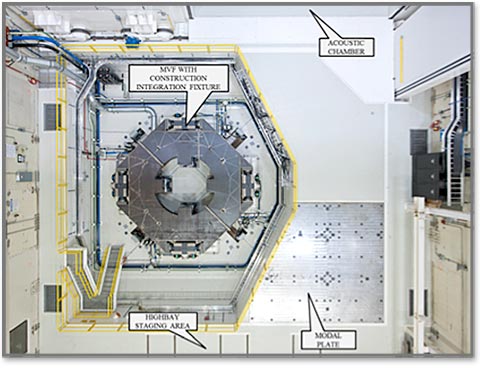
Mechanical Vibration Facility (MVF)
- Most powerful spacecraft shaker system in the world
- 6-degree-of-freedom (6-DOF) vibration table
- Reaction mass: 2.1 million kg
- Max payload: 34,000 kg; Max center-of-gravity height: 7.2 m
- Frequency range: 5–150 Hz
- Vertical: 1.25g; Lateral: 1.0g
- 1,024-channel high-speed data acquisition capable of sampling at 1kHz, 5kHz, 25kHz, 50kHz and 256kHz
- MVF seismic mass includes a ‘Modal Plate’. A 6” steel slab with >11E6 lb/in stiffness mounted to the 4.5 million pound seismic mass. Modal Plate mounting pattern diameter matches MVF table diameter mounting pattern.
EMI/EMC Test Facility
- World’s largest Reverberant EMI/EMC test chamber
- Utilizes the SPF vacuum chamber structure
- Supports:
- MIL-STD-461 (EMI)
- MIL-STD-464 (EME)
- IEC 61000-4-21 (chamber test techniques)
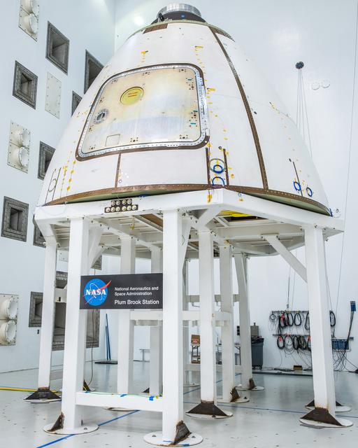
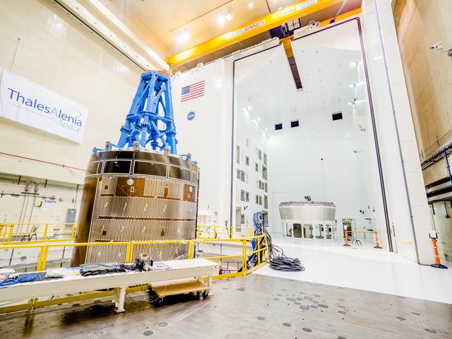
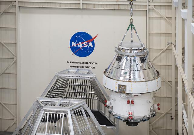
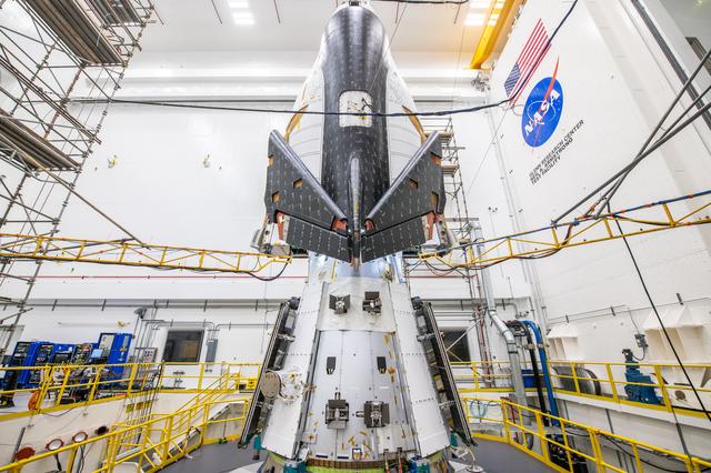
- Used for testing Artemis I Crew Service Module in 2020
Capabilities
Overall Functions
- Sustains high vacuum
- Produces cold environments via cryogenic cold shroud (–160°C, –250°F)
- Simulates solar and thermal radiation with an array of power controllers
- Provides a high degree of vibration isolation
Test Chamber
- 30.48-m- (100-ft-) diameter by 37.19-m- (122-ft-) tall test area
- Designed for external pressure of 1.19 bar (2.5 psig)
- Designed for internal pressure of 1.36 bar (5.0 psig)
- Chamber floor designed for a load of 272.16 t (300 tons)
- Two 15.24 by 15.24 m (50 by 50 ft) entrances, 180° apart
- Personnel entry door measuring 2.44 by 2.44 m (8 by 8 ft)
- 18.14 t (20-ton) vacuum compatible polar crane at top of chamber
- Chamber penetrations for power, data acquisition and high-pressure liquids and gases
- Concrete chamber enclosure, 1.83 to 2.44 m (6 to 8 ft) thick
- Aluminum Vacuum Chamber is equipped with hard points for suspending test hardware and reacting to loads during deployment tests.
- Four 60,000 lb rated hardpoints at aluminum chamber dome
- Four 10,000 lb rated hardpoints at aluminum chamber dome
- Two 8,000 lb rated hardpoints at aluminum chamber dome
- Multiple threaded restraint points on the aluminum chamber door
Vacuum Pumping System
- Roughing Pumps
- The mechanical roughing pump system consists of two systems (two trains), each with five stages consisting of 4 stages of roots blowers and 1 stage of rotary piston vacuum pumps with a total capacity 61,000 L/s (130,000 cfm).
- High Vacuum Pumps
- 10 1.22-m- (48–in.) diameter cryopumps with vacuum isolation gate valves (pumping speed—600,000 L/s/158,500 gal/s)
- 5 2,200 L/s (581.18 gal/s) turbopumps
- Ten 107-cm x 120-cm (42-in x 47-in.) LN2-cooled scavenger plates
- Pump down times (approx.):
- Atmospheric pressure to 20 Torr —2 hr
- 20 to 1×10⁻² Torr —3 hr
- 1×10⁻² to 4×10⁻⁶ Torr —2 hr
Water Systems
- Cooling tower water to dissipate waste heat produced by such devices as GN2 compressors and vacuum pumps
Gas Systems
- GN2: 3,822,800 L (135,000 ft³) at 166.49 bar (2,400 psig)
- GN2 (trailer): 1,982,200 L (70,000 ft³) at 166.49 bar (2,400 psig)
Cryoshroud
- Cryoshroud is 12.19-m- (40-ft-) diameter cylinder by 12.19 m (40 ft) tall
- Alternate configuration: 12.80 m wide by 24.38 m long (42 by 80 ft) with a 6.71-m (22-ft) height
- Requires reconfiguration
- 10 individual zones with separate temperature control to provide thermal uniformity
- Temperatures from –160°C to 80°C (–250°F to +175°F)
- Temperature transition of 0.42°C (0.75°F) per min
Cryogenic System
- 56,000 gallons of LN2 onsite storage for thermal vacuum operations
- Liquid nitrogen can be circulated through customer provided cold plates
- Additional provisions for rental storage up to 48,000 gallons
Thermal Systems
- 7 MW of power available for ancillary heating systems to provide heat flux and thermal conductance for lamps, heater panels and IR heaters
- Closed Loop Power Controllers
- 32 15-kW, 120-VDC channels
- 40 2.4-kW, 100-VDC channels
- 36 1.2-kW 120-VAC channels
- 6 0.2-kW, 20 VDC channels
- 5 50W, 120-VAC channels
Data Systems
- Facility data system
- Thermal data acquisition system (1 Hz continuous)
- High-speed test data acquisition system (1kHz, 5kHz, 25kHz, 50kHz and 256kHz)
- 256 channel system for all SEC facilities
Reverberant Acoustic Test Facility
- Reverberant acoustic chamber
- 14.5 by 11.4 by 17.4 m (47.5 by 37.5 by 57 ft)
- Chamber volume: 2,860 m³ (101,189 ft³)
- GN2 generation system
- Horn room with acoustic modulators and horns
- Acoustic control system
- Hydraulic supply system
Mechanical Vibration Facility
- Three-axis, six-degree-of-freedom, servohydraulic, sinusoidal base-shake vibration system
- Embedded steel plate for modal testing (2,100,000 kg/4,650,000 lb reaction mass)
- Large aluminum table: 6.7 m (22 ft) in diameter
- Wide annular mounting surface: 0.61 m (2 ft) wide
- 16 vertical cylinder actuators
- 8 lateral cylinder actuators
Data Systems
- High-speed test data acquisition system (1kHz, 5kHz, 25kHz, 50kHz and 256kHz)
- 1,024 channel system for RATF and MVF
- 256 channel system for all SEC facilities
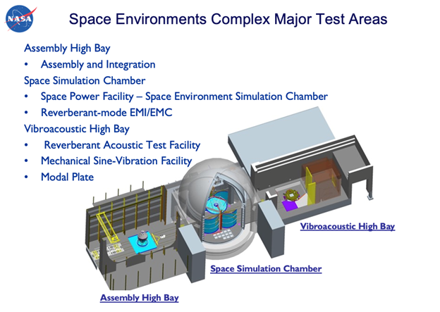
Overall Facility Layout/Configuration
The SEC was originally constructed in 1969 to perform nuclear and non-nuclear testing of large space systems needed for advanced missions beyond low Earth orbit. The facility was designed with excess capacity such as extremely large high bays, doors, power systems and supporting infrastructure to accommodate expanding test requirements well into the future of the space program.
The SEC aluminum vacuum chamber surrounded by the concrete vacuum enclosure is central to the facility. The large east and west aluminum and concrete chamber doors (15.24 by 15.24 m (50 by 50 ft.) lead directly into large high bays. The high bay on the east side of the facility, the Assembly High Bay, is primarily used for receiving, assembling, and preparing test hardware. The high bay on the west side of the facility, the Vibroacoustic High Bay, was originally constructed to safely disassemble nuclear components. Vibroacoustic High Bay houses the MVF and the RATF test facilities. North and south of the chamber and high bays are various supporting areas. North of the chamber are the facility control rooms, signal conditioning and instrumentation areas, machine shop, and two-story office building. The office building contains 41 offices and four conference rooms. South of the chamber are the electric substations, cryogenics room, vacuum room and mechanical rooms. The south outdoor courtyard areas behind the SEC support the LN2 and GN2 storage bottles, vaporizers, and cooling tower.

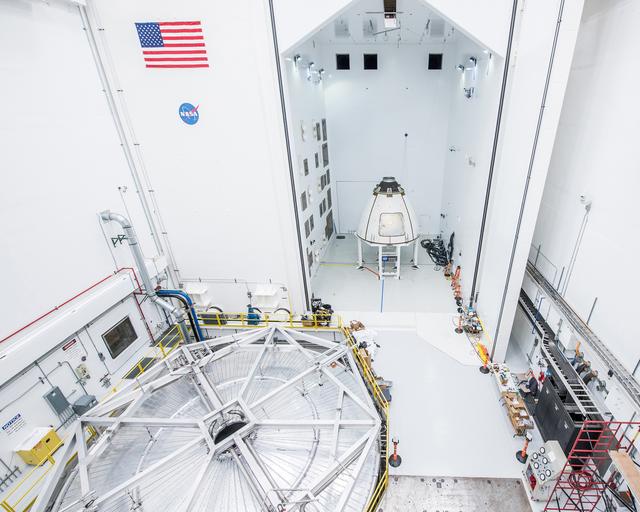
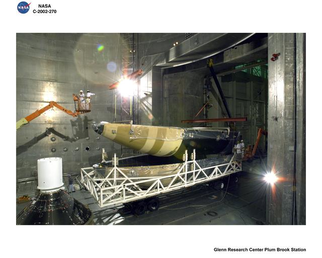
Assembly High Bay
Adjacent and east of the vacuum chamber is the Assembly High Bay, primarily used for setup and assembly of test hardware and ground-support equipment. The high bay is approximately 22.86 m (75 ft) wide by 45.72 m (150 ft) long with a clear height under the 22.68 t (25-ton) bridge crane of 22.86 (75 ft). Doors leading outdoors and into the vacuum chamber measure 15.24 by 15.24 m (50 by 50 ft). The high bay contains three sets of parallel, standard-gauge rail tracks to permit rolling stock and dolly transport from outdoors into the assembly high bay, the vacuum chamber, and the vibroacoustic high bay.
Vibroacoustic High Bay
Adjacent and west of the vacuum chamber is the Vibroacoustic High Bay, which houses the MVF, a modal floor, and the RATF facility. The high bay has a clear height under the (18.14 t) (20-ton) bridge crane of 62 feet. Doors into the vacuum chamber measure 15.24 by 15.24 m (50 ft by 50 ft).
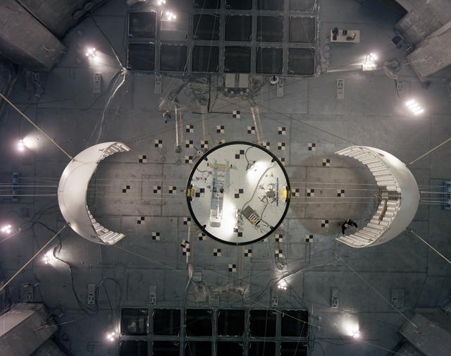
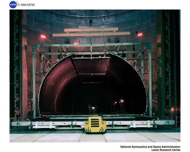
Space Simulation Vacuum Chamber
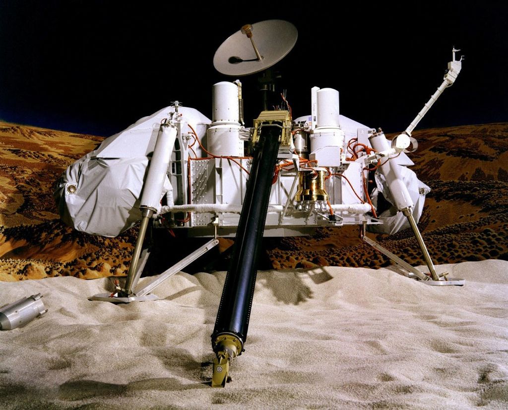
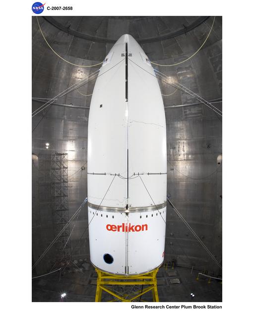
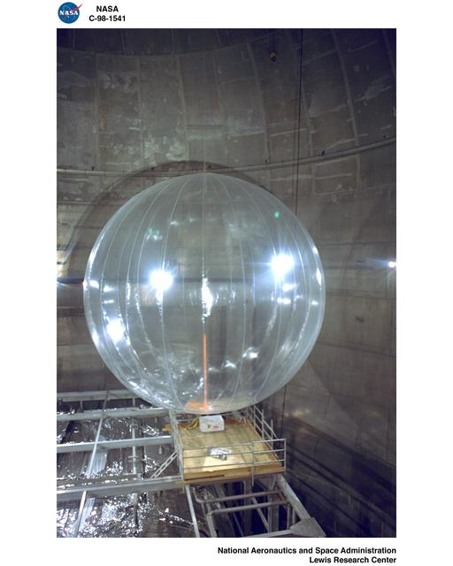
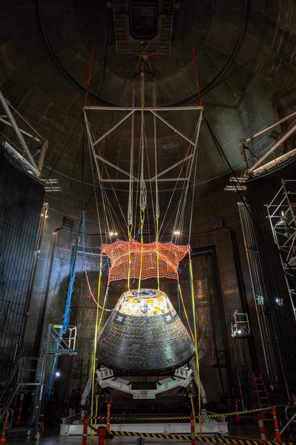
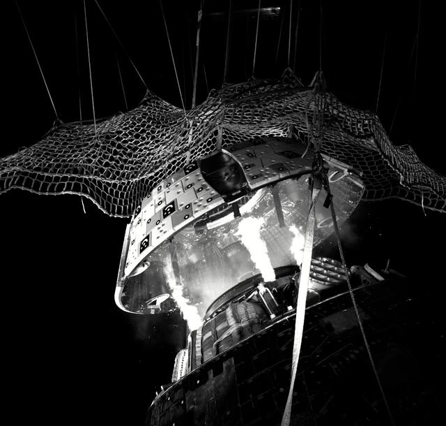
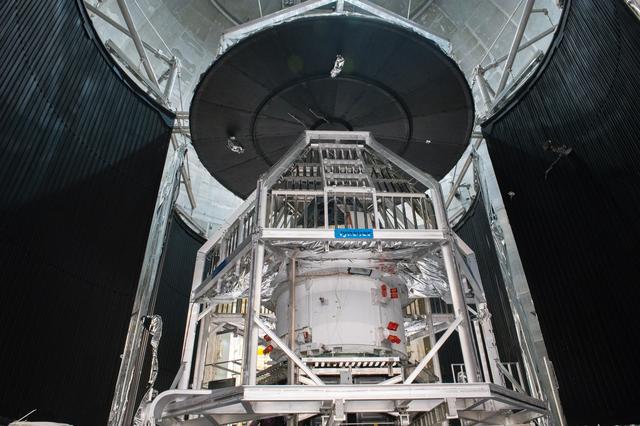
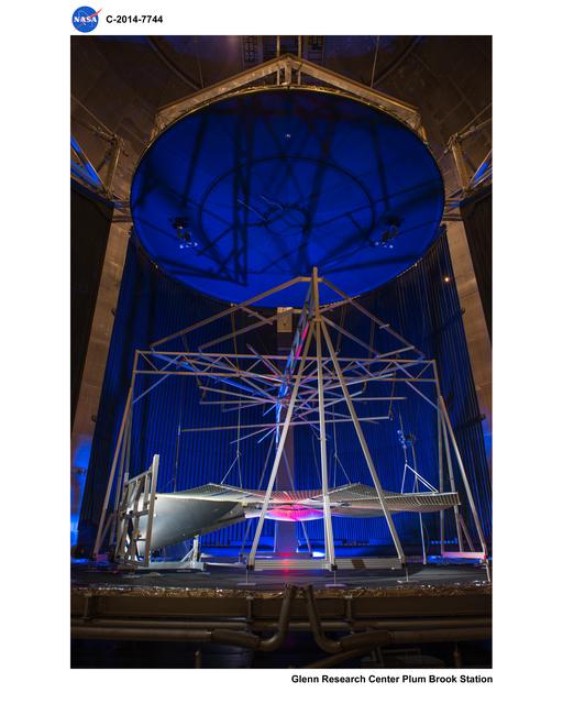
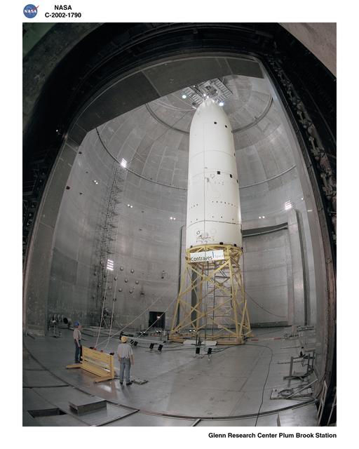
The SEC Vacuum Chamber, known as the Space Power Facility (SPF), is the world’s largest vacuum chamber with a volume of 22,653 m³ (800,000 ft³) and measuring 30.5 m (100 ft) in diameter and 37.2 m (122 ft) high. It has 15.24-m- (50-ft-) by 15.24-m- (50-ft-) loading doors on each side that lead to high bays. The chamber features all-aluminum construction, including a removable polar crane with an 18.1 t (20 ton) critical lift trolley and a 9.1 t (10 ton) auxiliary hook. The chamber’s unique size and capabilities have made it the ideal facility for conducting tests such as full-scale rocket-fairing separation tests, Mars Lander system tests, deployable solar sail and solar array tests, International Space Station radiator deployment tests, and high-energy experiments.
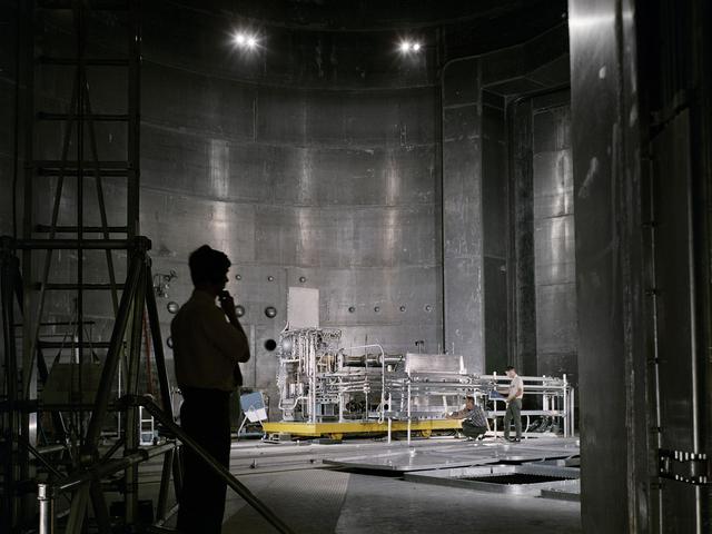
The vacuum chamber was designed and constructed to test both nuclear and non-nuclear space hardware in a simulated space environment. Although the facility was designed for testing nuclear hardware, only non-nuclear tests have been performed throughout its history. The vacuum chamber is surrounded by an equal-volume concrete enclosure that is typically reduced in pressure to 15 Torr during chamber operations. The vacuum chamber incorporates several electrical and instrumentation penetrations and several blank penetrations at various locations around the chamber perimeter. Removable rail tracks in the chamber can be used in conjunction with rail dollies or the cryoshroud floor(s) to transport hardware or test articles through the facility and chamber. The chamber provides a visibly clean environment and provides an ultimate empty-chamber vacuum capability of < 4×10⁻⁶ Torr using a combination of roughing pumps and high-vacuum equipment. The roughing system consists of two identical five-stage parallel trains of rotary-lobe blowers and rotary-piston mechanical pumps, which pump the chamber and annulus simultaneously to 15 Torr, and subsequently the chamber to 10 mTorr. High-vacuum is achieved using five 2,000-liter/sec turbomolecular pumps and 10 50,000-liter/sec cryopumps. The chamber can reach a vacuum level of 4×10⁻⁶ Torr in less than eight hours.
The chamber currently is outfitted with a fully removable, reconfigurable cryoshroud for background heating and cooling that provides a high-emissivity thermal background environment of –160°C to 80°C (–250°F to +175°F) within a 12-m- (40-ft-) diameter by 12-m- (40 ft-) high envelope. The cryoshroud is warmed and cooled using a recirculating gaseous nitrogen (GN2) system. The system uses compressor heat-of-compression to provide up to 80°C (175°F) wall temperatures, and a heat exchanger/liquid-nitrogen (LN2) desuperheater to provide temperatures down to –160°C (–250°F). The chamber produces variable thermal zones by a combination of closed-loop power controllers (28 15-kW, 120-VDC channels; 40 2.4-kW, 100 VDC channels; 36 1.2-kW 120-VAC channels, and six 0.2-kW, 20 VDC channels) that typically connect to customer-supplied heaters. Zone heater systems can be provided upon request.
High speed data is collected for the vacuum chamber via a Mobile Data Acquisition System (MDAS), of which is a GRC-ATF station asset consisting of a 256-channel high-speed digital system, and a low-speed data acquisition system that collects temperature data, vacuum instrumentation, and power controller parameters.

Space Simulation Vacuum Chamber Data
| Chamber Parameters | |
|---|---|
| Ultimate Test Pressure | < 4×10⁻⁶ torr |
| Cryoshroud Temperature | –160 °C to 80°C (–250 °F to 175 °F) |
| Chamber Pumping Speed | 500,000 L/s at 10–5 Torr |
| Instrument Penetrations (Varies by Test) | |
|---|---|
| Type T Thermocouple | 1500 |
| Type E Thermocouple | 112 |
| RTD | 16 |
| 37-pin Connectors | 60 |
| BNC Coaxial Connector | 96 |
| Ethernet (Cat6 Shielded) | 26 |
| Physical Characteristics | |
|---|---|
| Chamber Diameter | 30.48 m (100 ft) |
| Chamber Height | 37.18 m (122 ft) |
| Chamber Volume | 22,653 m3 (800,000 ft3) |
| Blank Ports | Three each, 0.5 m diam. |
| Blank Ports | Ten each, 0.68 m diam. (alternately used for high-power feed-through) |
| Blank Ports | One each, 0.68 m diam. |
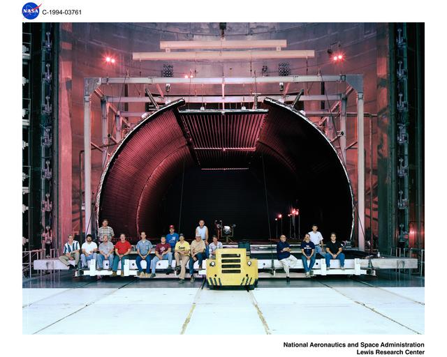
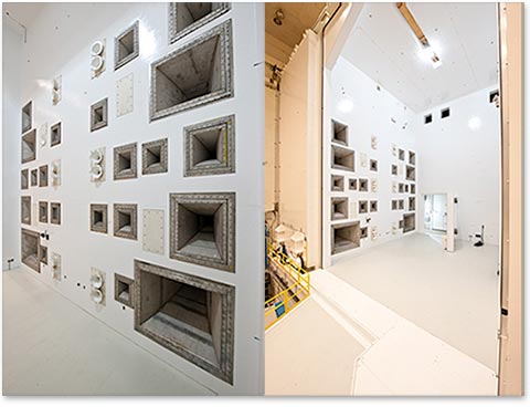
Reverberant Acoustic Test Facility
The Reverberant Acoustic Test Facility (RATF) chamber is located within the Vibroacoustic High Bay, taking advantage of the 1.8-m- (6-ft-) thick surrounding concrete walls to help attenuate sound migration through the SEC. The high bay also serves as redundant protection from the RATF nitrogen atmosphere during operation. The RATF is a 2,860-m³ (101,189-ft³) reverberant acoustic chamber capable of achieving an empty-chamber acoustic overall sound pressure level (OASPL) of 163 dB. The facility structure is designed for a future upgrade to 166-dB OASPL, including areas in the horn room wall that have been left blank for future installation of additional modulators/horns. The RATF includes various supporting subsystems including a GN2 generation system, horn room with acoustic modulators and horns, acoustic control system and hydraulic supply system. Test articles are mounted onto elevated customer-provided mounting fixtures for testing using a 30 ton bridge crane. The chamber can be operated as a Class 100,000 clean room once the access doors are closed and the facility is cleaned. The combinations of servohydraulic and electropneumatic noise modulators utilize GN2 capable of producing a tailored wide range of acoustic spectra in the frequency range from 31.5 Hz up to the 10,000 Hz one-third octave bands. RATF is capable of operating in the closed loop in the frequency range of 31.5Hz third octave band to 1200 Hz third octave bands, with an approximate roll of 1-2 dB per one third octave band from 1600 Hz to 10,000 Hz. The RATF chamber internal dimensions are 11.4 m wide by 14.5 m deep by 17.4 m high (37.5 by 47.5 by 57 ft).
A maximum of 19 control microphones can be placed around the test article for closed-loop control using the acoustic control system (ACS). The ACS, control microphone or other response instrumentation (accelerometers, microphones) may be input into the analog abort system (AAS) to provide automatic shutdown capability. Each of the 23 servohydraulic acoustic modulators is coupled with individual horns of six different cut-off frequencies. The horns high pass cut-off frequencies are 25 Hz, 35 Hz, 50 Hz, 80 Hz, 100 Hz, and 160 Hz. Each of the 13 electro-pneumatic acoustic modulators is coupled with individual 250 Hz horns. This combination of modulators and horns provides for an extremely variable and tailored acoustic spectrum. Threaded inserts are located in the floor for attachment of test article mounting fixtures.
The east side of the chamber has a large rolling door and hinged door to provide access to the chamber up to 10.5 m (34.5 ft) in width. A 5.5-m-high by 4.2-m-wide (18- by-14-ft) door is located on the west side of the chamber for loading equipment when the vacuum chamber is occupied.
In preparation for operations, the Vibroacoustic High Bay is secured, and support systems (hydraulics, compressed air, LN2, GN2, HVAC (heating, ventilation, and cooling), and video) are set up and energized. The acoustic chamber is filled with a predetermined level of GN2. The FCS verifies that a matching modulator selection file agrees with the ACS and subsequently provides a run permit to the ACS. The ACS performs a self-check, and the operator initiates testing using the tailored choice of modulators/horns. The nitrogen generation system automatically vaporizes LN2 into GN2 as required up to 1,981 standard cubic meters per minute (70,000 scfm). At the conclusion of testing, fresh air is force ventilated into the chamber via the HVAC system to purge the chamber of nitrogen for safe entry. Temperature, humidity, and oxygen monitors are located in the chamber and high bay.
Data are acquired at the RATF via the facility data acquisition system (FDAS), a 1,024-channel high-speed digital system.
The RATF has been tested up to a maximum OASPL of 162.9 dB, relative to an empty chamber. The following are various characteristics of the acoustic facility.
Reverberant Acoustic Test Facility Data
| Parameters | |
|---|---|
| Team Mk VI Modulators | 12 |
| Team Mk VII Modulators | 11 |
| Wyle WAS5000 Modulators | 13 |
| Horns | 36 |
| Max. Empty-chamber SPLa | 162.9 dB OASPLb |
| Frequency Range | 31.5 Hz to 10 KHz 1/3 Octave Bands |
| Physical Characteristics | |
|---|---|
| Chamber Dimensions | 14.5 by 11.4 by 17.4 m(47.5 by 37.5 by 57 ft) |
| Chamber Volume | 2,860 m3 (101,189 ft3) |
| Crane Capacity | 27,215 kg (60,000 lb) |
| Floor Loading | 54,422 kg (120,000 lb) |
| Blank Penetrations | 25 at 0.15 m (6 in.) diam.2 at 0.20 m (8 in.) diam. |
| a) Sound pressure level b) Acoustic overall sound pressure level |
Mechanical Vibration Facility
General Description
The Mechanical Vibration Facility (MVF) is a three-axis, six-degree-of-freedom, servohydraulic, sinusoidal base-shake vibration system located within the same Vibroacoustic High Bay as the RATF on the west side of the vacuum chamber. The proximity to the RATF allows shared use of the hydraulic system, safety systems, high-speed data acquisition system, and surveillance system. The MVF system consists of reaction mass, four horizontal servohydraulic actuators, 16 vertical servohydraulic actuators mounted on double-spherical couplings, an aluminum table, a hydraulic supply system, a table control system (TCON), a vibration control system (VCON), an analog abort system (AAS), and the same FCS used by the RATF.
The MVF reaction mass includes an embedded steel plate for modal testing. The 2,100,000-kg (4,650,000-lb) reaction mass is used to resist the vibratory energy from the hydraulic actuators, table and test article, transferring the energy into the shale bedrock foundation. The reaction mass has been sized such that it has sufficient inertia mass and stiffness to react against the forces applied by the actuator/couplings during sine vibration testing. The reaction mass has been designed to accommodate future growth in vibration system and test article mass. The existing actuator and table design is for sine sweep capability of maximum 1.25g (peak) from 5 to 150 Hz in the vertical axis and maximum1.0g from 5 to 150 Hz in each of the horizontal axes. These maximums are based on a a test article mass of 34,000 kg (75,000 lb) with a center of gravity elevation of 7 m (23 ft). Currently, the facility is commissioned for sinusiodal control in three independent axes.
The MVF system design uses a large aluminum table approximately 6.7 m (22 ft) in diameter with a 0.61-m (2-ft) wide annular mounting surface centered about a 5.5-m (18-ft) nominal diameter. Table weight is partially off-loaded from the system via four inflatable airbags. A MVF table expander has been added to provide customer interface attachment with mounting patterns ranging from 5” to 193” diameter.
The table vertical actuation is provided by 16 hydraulic cylinder actuators with double-spherical couplings attached to the reaction mass. The vertical actuator assemblies provide the controlled vertical sine vibration, enable horizontal vibration and provide overturning constraints during horizontal vibration. The table rests on the double-spherical couplings. The double-spherical couplings couple each vertical actuator to the table and provide high-axial stiffness to deliver the vertical vibratory force during vertical excitation. Each double-spherical coupling has internal pressure sensors to enable the vibration controller to limit forces. Four horizontal actuators provide the controlled horizontal sine vibration and comprise two single-ended pistons, which maintain outward force through hydrostatic pad-bearings to the table. The horizontal actuator assemblies provide vertical alignment during vertical actuation. The system is designed to permit testing in three independent axes without removing or lifting the test article from the table.
A customer-supplied adapter ring is necessary to attach the test article to the vibration table mounting holes. The Vibroacoustic High Bay is secured, the support systems (hydraulics, compressed air, life safety, video and table mode) are set up and energized, and interlocks are verified (including vibratory mode-choice setup) using the FCS. The TCON and FCS communicate with the table actuator servovalve drivers; position the table to a lifted, centered, ready position; and verify all servodrivers are started and ready. Operators then initiate the VCON to generate the sine wave inputs to the servovalve controllers, establishing vibration. The VCON controller generates drive voltage waveforms for each servovalve driver to satisfy the control and limit channel constraints from the test article (outer-loop control), and each servovalve driver maintains a closed-loop control to each actuator (inner-loop control). The VCON has 64 analog input channels, which can be assigned to control channels, limit (notch) channels or response monitoring channels, where these input channels can also be set to alarm and/or abort a test. Assuming a control channel configuration of using four tri-axial accelerometers (12 ch), plus the fixed need for the facility’s control channels, a customer can then use up to 31 of the analog input channels for test article limit channels. Data are acquired at the MVF via the FDAS, a 1,024-channel high-speed digital system.
MVF seismic mass includes a ‘Modal Plate’. A 6” steel slab with >11E6 lb/in stiffness mounted to the 4.5 million pound seismic mass. Modal Plate mounting pattern diameter matches MVF table diameter mounting pattern.
Mechanical Vibration Facility Data
| Parameters | |
|---|---|
| Max. Test Article Mass | 34,000 kg (75,000 lb) with Base Table 22,679 kg (50,000 lb) with Table Expander |
| Max. Cg Above Table | 7.2 m (23.6 ft) |
| Seismic Mass | 2,100,000 kg (4,650,000 lb) |
| Max. Vertical Static Force | 3,203 kN (720,000 lb) |
| Max. Vertical Dynamic Displacement (peak-to-peak) | 3.18 cm (1.25 in.) |
| Max. Vertical Velocity | 41.7 cm/s (16.4 in./s) |
| Max. Lateral Static Source | 1,139 kN (256,200 lb) |
| Max. Lateral Dynamic Displacement (peak-to-peak) | 3.048 cm (1.2 in.) |
| Max. Lateral Velocity | 33.8 cm/s (13.3 in./s) |
| Frequency Range | 5 to 150 Hz |
| Sine Sweep Rate | Dwell to 4 oct/min |
| Physical Characteristics | |
|---|---|
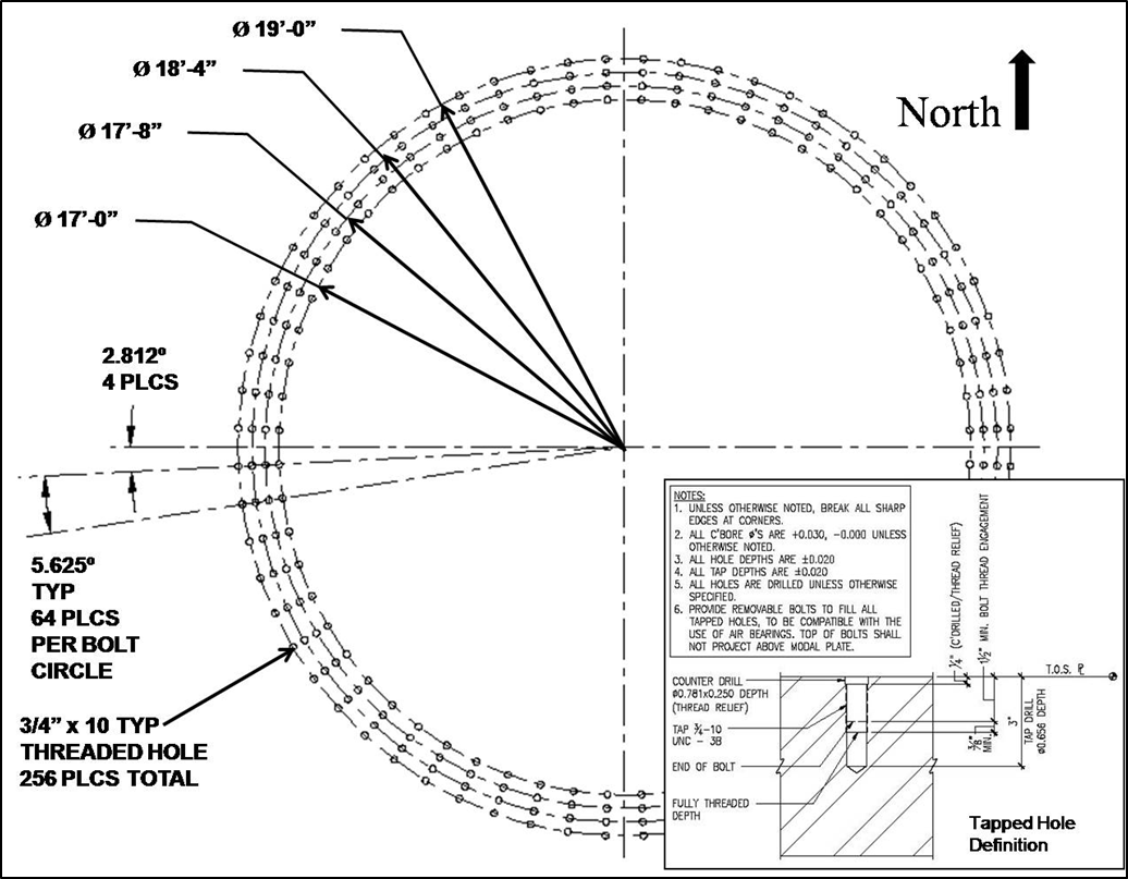
| Table Mounting Pattern – Base Table Mounting Diameters | Sixty four threaded inserts of ¾”-10 pitch at 1.5” deep @ bolt circle pattern diameters of 228”, 220”, 212” and 204” |
| Table Expander Mounting Patterns | 872 total threaded inserts of 5/8”-11 pitch at 1.5” deep @ bolt circle pattern diameters ranging from 5” to 193” |
| Max. Test Article Height | 23.5 m (77 ft) |
| Max. Test Article Height Below Crane Bridge | 20.4 m (67 ft) |
| Sine Sweep Rate | Dwell to 4 oct/min |
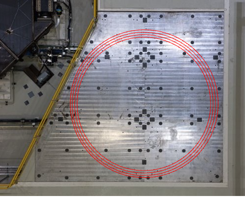
Modal Vibration
The SEC has a fixed-base modal testing floor incorporated into the MVF seismic mass. Some high-level modal floor capabilities are reported in this section.
The modal floor provides for modal testing of a 75,000 lb. test article up to 18 feet in diameter. The modal floor has an average vertical stiffness of 11E6 lb. /inch. The modal floor consists of a 6” thick steel plate structure anchored to the concrete seismic mass.
The modal floor is at ground level, USGS elevation 658’-0”; therefore, providing a 63-foot clear height under the bridge crane, and a 73-foot clear height to the Vibroacoustic High Bay ceiling. The modal floor can accommodate a 20-foot diameter test article. The modal floor has anchoring points for the test article, the threaded holes are 3/4”-10 with 1.5” depth. The steel plate includes four concentric female-thread anchor points at bolt circle diameters of 204”, 212”, 220”, and 228”.
Electromagnetic Interference / Compatibility (EMI/EMC) Test Facility
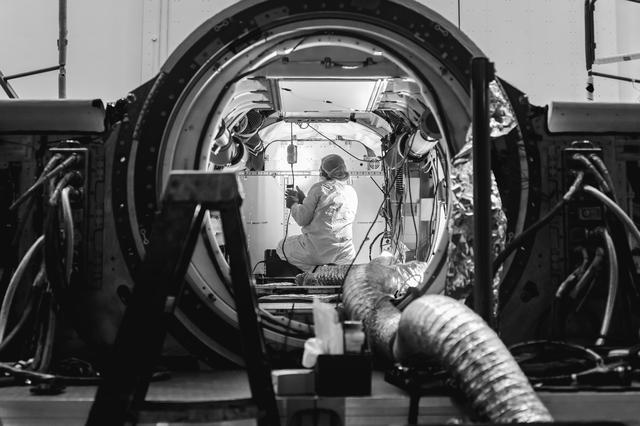
Designed specifically as a large-scale thermal-vacuum test chamber for qualification testing of vehicles and equipment in outer space conditions, it was discovered in the late 2000s that the unique construction of the SPF interior aluminum vacuum chamber also makes it an extremely large and electrically complex RF cavity with excellent reverberant RF characteristics. In 2009, these characteristics were measured by NIST and others[1] after which the facility was understood to be not only the world’s largest vacuum chamber, but also the world’s largest EMI/EMC test facility. In 2011, NASA Glenn successfully performed a calibration of the aluminum vacuum chamber[2] using IEC 61000-4-21 methodologies[3]. As a result of these activities, the SPF is capable of performing radiated susceptibility EMI tests for vehicles and equipment per MIL-STD-461 and able to achieve MIL-STD-461F limits above approximately 80 MHz. In the spring of 2017, the low-power characterizations and calibrations from 2009 and 2011 were proven correct in a series of high-power tests performed in the chamber to validate its capabilities. The SPF chamber completed EMI radiated susceptibility testing of the Artemis I CSM for the Exploration Mission 1 of NASA’s Orion spacecraft in 2020, demonstrating this capability with spaceflight hardware.
1. NIST TN-1558 – An electromagnetic evaluation of the NASA space power facility at Neil A. Armstrong Test Facility (ATF) — https://archive.org/details/electromagnetice1558koep
2. NASA TM—2014-218363 – Space Power Facility Reverberation Chamber Calibration Report — https://ntrs.nasa.gov/search.jsp?R=20150000254
3. IEC 61000-4-21:2011 – Electromagnetic compatibility (EMC) – Part 4-21: Testing and measurement techniques – Reverberation chamber test methods — https://webstore.iec.ch/publication/4191
4. MIL-STD-464 – Electromagnetic Environmental Effects Requirements for Systems — http://quicksearch.dla.mil/qsDocDetails.aspx?ident_number=35794
5. MIL-STD-461 – Requirements for the Control of Electromagnetic Interference Characteristics of Subsystems and Equipment — http://quicksearch.dla.mil/qsDocDetails.aspx?ident_number=35789
6. IEEE Paper – Overview of the Threat of IEMI — http://ieeexplore.ieee.org/stamp/stamp.jsp?arnumber=6351829
7. IEC 61000-4-36 (2014) – IEMI immunity test methods for equipment and systems — https://webstore.iec.ch/publication/4221
Contact
Space Environments Complex Facility
Facility Manager — Jose Mendez
216-389-6173
Jose.G.Mendez@nasa.gov
Neil A. Armstrong Test Facility
Deputy Director: David Taylor
216-386-7771
David.E.Taylor@nasa.gov
Using Our Facilities
NASA’s Glenn Research Center in Cleveland provides ground test facilities to industry, government, and academia. If you are considering testing in one of our facilities or would like further information about a specific facility or capability, please let us know.
/Hubble%20Space%20Telescope%20(A).png)