


Vertical Motion Simulator
Technical Details

ICABs
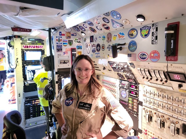
The interface between the pilot and the simulator at the VMS is a structure called the Interchangeable Cab (ICAB), which recreates the cockpit of an aerospace vehicle. Sitting in an aircraft seat, the pilot affects the simulation by manipulating the flight controls and the switches and buttons on the instrument panel. Sensory information is delivered to the pilot in many forms: visual cues from the out-the-window scene and the flight instruments, motion cues from the motion base and the vibration generator under the seat, and auditory cues, which reproduce the sounds of flight.
In keeping with the VMS mission of supporting any aerospace vehicle, the ICAB can simulate passenger and cargo transport planes, rotorcraft, fighter aircraft, spacecraft, and more. This uncommon flexibility is made possible by the ability to change many of the components inside the ICAB, including the flight controls, instruments, and seats. The VMS maintains a large selection of components that can be modified, and new components can be designed and fabricated according to researchers’ needs.
Not only are many of the components within the ICAB interchangeable, but the ICAB itself is portable and can be moved to different areas of the facility according to the phase of a simulation.
During build-up, when the interior of the cab is configured, it rests in one of two fixed-base labs, where all parts of a simulation except motion can be run. In this way, the cab hardware and the simulation software can be tested together to ensure smooth operation prior to an experiment. Some of the research conducted at the VMS does not require motion and occurs in the fixed-base labs. However, the cab is usually next moved to the motion base.
The key to efficiency at the VMS lies in the flexibility afforded by having five ICABs. This allows the simultaneous development of different simulation experiments and optimizes the use of the single motion base. Removing one cab from the motion base, installing the next cab, and testing it with motion requires only a day.
The capabilities of changing components within a cab and operating multiple cabs in different areas of the facility dictate that the cabs have standardized elements. To this end, each ICAB is made of four substructures:
- The removable canopy can be lifted off for easy access to the interior during cab build-up. When in place, the removable canopy keeps out light and sound for the simulation pilot.
- The fixed canopy is a permanent structure and forms the rear wall of a cab. Personnel enter and exit through a door in this substructure. The fixed canopy also provides surfaces for mounting equipment and for connecting electrical and electronic lines from the rest of the simulator.
- The base forms the floor of the cab. It can be fastened to the motion base and serves as the attachment point for the other substructures. It also secures much of the equipment that changes from simulation to simulation: the seats, flight controls, and instrument panel. In addition, hydraulic lines to the cab are attached to the underside of the base.
- The image presentation system (IPS) delivers the out-the-window graphics, which represent the outside world to the pilot. The IPS is not changed between simulations because exact placement of the optics is important in aligning the imaging components with one another and with the pilot’s eye. The IPS configuration is unique to each cab and is used to simulate specific types of aircraft, as shown below.
Motion Base
The motion base at the VMS features six degrees of freedom, meaning that the cab, with the pilot inside, can be driven in the six ways an aircraft moves. This includes the three translational degrees of freedom (vertical, lateral, and longitudinal) and the three rotational degrees of freedom (pitch, roll, and yaw).
Providing the vertical degree of freedom is the vertical platform, which spans the 70-foot length of the building and supports the mechanisms for the remaining degrees of freedom.
Supporting the vertical platform are two columns that extend into 75-foot-deep shafts. Guides on either end and on one side of the vertical platform keep it aligned.
Moving the 70-ton weight of the vertical platform and its load quickly is made possible by an equilibrator. This system pressurizes the two supporting columns with nitrogen, neutralizing the immense load. Eight 150-horsepower motors drive the columns, accelerating the vertical platform up to 22 feet/second/second, or almost 3/4 g.
Providing lateral movement is the lateral carriage, which is capable of moving 40 feet toward the viewer. The lateral carriage is driven by four 40-horsepower electric motors.
Longitudinal movement is provided by the longitudinal carriage, with a range of 8 feet; in the photograph, it would move from left to right. The longitudinal carriage is driven by telescoping hydraulic actuators.
For flexibility in the delivery of cues, the cab can be mounted 90 degrees from the usual orientation. In this way, the larger 40-foot range can be used for longitudinal, instead of lateral, movements. For example, a study of the parachute used to slow the Space Shuttle Orbiter after landing used this orientation to provide maximum deceleration cues.
Like the longitudinal carriage, the three rotational degrees of freedom are driven hydraulically. The rotating center post provides yaw movements, and the pitch and roll actuators provide pitch and roll movements.
OTW Graphics
The out-the-window (OTW) graphics—the computer-generated images that simulate the outside world for the pilot—offer both flexibility and accuracy. Numerous rural and urban locations, such as airports in the United States and abroad, have been simulated, and all can be modified as needed for specific simulation experiments. When required by researchers, new locations, whether real or imaginary, can also be generated.
Each OTW scene depends on a database, the software that contains the relevant characteristics of a geographic location. Numerous three-dimensional moving and stationary models are created independently, then included in the database. Aircraft, ground vehicles, and buildings are common three-dimensional models. Ships, including several aircraft carriers for experiments in landing and takeoff, have also been simulated.
The VMS maintains two image generators, one with five channels and one with six. Each channel corresponds to the image displayed in a single window. The image generators are capable of independent eyepoints; in other words, they can display the scene from different positions simultaneously. This enables the pilot and copilot to view the scene accurately from their slightly different positions. It also allows the exterior of the simulated aircraft to be viewed by the researcher from any location in the database.
Objects at a distance are seen with less detail than those nearby, and the image generators save time by omitting unseen details. To accomplish this, databases are designed with up to six levels of detail. The image generators present the transitions between levels smoothly so the simulation pilot is unaware of them.
The largest object simulated at the VMS is the earth, used in simulating the landing of the Space Shuttle Orbiter. Because any part of the earth may be seen from higher elevations, all areas have been developed at the lowest level of detail. As the shuttle gets closer to the earth, visible areas are displayed with increasing detail. However, to avoid taxing the image generators, only those areas used for low-level flight are developed at the highest level of detail. Areas as large as 10,000 square kilometers have been simulated at this level.
The process of image generation begins when the host computer samples the state of the aircraft, including its position, orientation, and speed, along with any input from the pilot via the flight controls. The host computer then extrapolates the aircraft’s state for the instant the pilot will view the image; in this way, the pilot will not see a graphic that’s a split-second old. This information is sent to the image generator.
The image generator also performs an extrapolation, this time to account for the fact that it operates at a different rate than the host. The image generator then computes which scenery the pilot would see and prepares it with the appropriate level of detail. The image generator next converts the three-dimensional information for display on a two-dimensional surface. Finally, it prepares the image to be displayed electronically and sends it to the cab.
In the cab, the pilot does not directly view the monitor. To make the image appear distant, it is first reflected by the back of the window onto a section of spherical mirror. Because of the mirror’s shape, the reflected light rays are parallel, resulting in an image that appears distant. The image then passes through the window to the pilot’s eye. Because of this dual function, the window is called a beam splitter.
Because the image generator computed the scene for a split second into the future, the image arrives at the pilot’s eye at just the correct moment. At any one time, three images are at one stage of processing or another. The OTW system displays a new image 60 times a second, delivering smooth and accurate visual cues to the pilot.
Flight Instruments
To support its mission of simulating any aerospace vehicle, the VMS simulates all types of instruments, from the older dial-type (analog) instruments to the most modern electronic (digital) displays. Analog instruments at the VMS can be modified as needed, and electronic instruments can be programmed to display information in numerous ways. Researchers frequently request that flight instruments still in the design stage be simulated for testing.
The VMS demonstrates exceptional flexibility in the simulation of flight instruments. The ability to modify analog instruments and to customize electronic displays enables the simulation of virtually any existing instrument, as well as instruments in the design stage. The accurate delivery of information via flight instruments is one important part of real-time simulation at the VMS.
Flight Control
One important key to the accuracy of a simulation, and to a realistic experience for the pilot, lies in the quality of the flight control system. This is especially important at the VMS because of the many experiments conducted in handling qualities and controllability.
The hydraulic flight control system at the VMS is called a control loader, or loader. It must accurately measure a pilot’s input and provide high-fidelity cues to the pilot; in other words, the pilot’s controls must feel as they would in a real aircraft. The control loader must also be extremely versatile to simulate all the controls of any aerospace vehicle.
The VMS has a large collection of pilot’s controls that are made specifically for simulation. On the left is a wheel and column, which is typically used in transport aircraft. Next to that is a center stick, as it is called in fighter jets; in helicopters it is usually referred to as a cyclic. On the right is a hand controller, also called a side stick. Pilots use these controls to pitch and roll the aircraft.
Most aircraft have pedals, which a pilot uses to yaw the aircraft and, in many cases, to brake on the runway. Another common flight control is a collective, which is used in helicopters to regulate power. Power consoles, with levers for throttles, are used in planes. They are not part of the hydraulic control loader, but have a simple mechanical adjustment for friction.
In addition to physically changing the pilot’s controls, their response can be modified according to the aircraft being simulated. The following variable characteristics can be programmed and even changed during flight:
- Position Trim (Trim) – The position to which a flight control returns when the pilot releases it.
- Force Breakout (Return-to-Center Force) – One force that returns a control to Trim. This is a constant force; that is, the force applied toward Trim remains the same despite the displacement (how far the control is moved) and velocity (how fast a control is moved).
- Force Gradient (Spring Force) – Another force that returns a control to Trim, but one that varies with displacement – the farther the control is moved, the stronger the force applied toward Trim.
- Force Friction - A force that is opposite to the direction of movement. Force friction is a constant force.
- Damping - Another force that is opposite to the direction of movement. Damping varies with velocity – the faster a control is moved, the stronger the force.
- Hard Stop – A force that simulates a mechanical limit of travel. By varying the Hard Stops, the range of travel can be adjusted.
In the cab, a pilot’s control is connected to one or more actuators, which measure the forces a pilot applies to the control. They also regulate the forces applied by the loader to give the control the appropriate feel. Each axis of a control is connected to an actuator. For example, a stick would have two: one each for roll and pitch commands.
A simulation begins for the control loaders when the host computer downloads the characteristics the controls should exhibit to the digital-analog interface, which converts the signal from digital to analog. This signal is then conveyed to an analog computer. Then three factors – the force, velocity, and displacement of the pilot’s input – are measured by a transducer in an actuator. The results are conveyed as analog signals to the analog computer, which generates a force command. The electronic controller processes this signal, together with the force input by the pilot, to generate a signal that is sent to the actuator, resulting in the proper feel being imparted to the flight control.
Besides regulating the flight controls, the control loader can generate vibrations in the pilot’s seat that are not produced by the motion base. These high-frequency, low-amplitude (fast and small) motions vary according to the aircraft’s state and reproduce the vibrations characteristic of different aircraft. This vibration generator, or seat shaker, is most often used in the simulation of rotorcraft.
The versatile, high-fidelity control loader at the VMS provides for the accurate measurement of pilot input and the delivery of realistic cues. The ability to customize the pilot’s controls for each experiment, and to change their response by programming variable characteristics, contribute to the pilot’s experience of realistic, real-time simulation.
VMS Lab
From the VMS Lab, engineers control, monitor, and record a simulation and communicate with the simulation pilot. Visiting researchers, whose needs shape a simulation experiment, work at this station in the VMS Lab.
Researchers control many aspects of a simulation. They often change the simulation’s configuration. For example, they could present a shuttle pilot with different landing sites or conditions of visibility. They can also introduce failures to see how the pilot and the aircraft respond. Failures during a shuttle simulation might include the blowout of a tire during landing or the failure of the guidance system that helps astronauts locate a runway.
The VMS Lab provides many ways to monitor an experiment. Engineers can simultaneously view a computer-generated graphic of the exterior of the simulated aircraft, monitor the same out-the-window scene as the pilot, and even watch a video of the motion base.
To observe important information as the experiment occurs, researchers often use data display monitors. Data is displayed during a run (a particular flight task flown by the pilot) and can be updated with summary information at the end of each run. Data can be displayed as text or in graphic form, such as the gauges seen in this data display. In addition, a visual representation of the task can be created. In this case, researchers could see when the simulated helicopter, represented by the white circle in the lower right diagram, moved within specified bounds. In the lower left diagram, the red circle represented the position of the center stick flight control.
Researchers can record many aspects of a simulation for later analysis. At the end of every simulation experiment, compact discs with series data and summary data are made. Series data are variables recorded many times each second. Summary data are collected at the end of each run and include variables such as the conditions at the start of each run and selected minimum and maximum values. Up to 1300 variables each can be collected for series and summary data. This information can also be made available periodically during the simulation.
Some researchers make audio-video recordings. A common recording includes voice communications with the pilot and the front window of the out-the-window display. A head-up display can be included, if used. The data display monitor can also be recorded, and a video camera sometimes records the pilot’s actions.
The VMS Lab provides numerous flexible tools for visiting researchers to control, monitor, and record simulations. The results of an experiment – the extensive data documenting the simulation – enable scientists to further their research, thereby advancing the field of aeronautics.