


4.1 Stakeholder Expectations Definition
4.2 Technical Requirements Definition
4.3 Logical Decomposition
4.4 Design Solution Definition
The Design Solution Definition Process is used to translate the high-level requirements derived from the stakeholder expectations and the outputs of the Logical Decomposition Process into a design solution. This involves transforming the defined logical decomposition models and their associated sets of derived technical requirements into alternative solutions. These alternative solutions are then analyzed through detailed trade studies that result in the selection of a preferred alternative. This preferred alternative is then fully defined into a final design solution that satisfies the technical requirements. This design solution definition is used to generate the end product specifications that are used to produce the product and to conduct product verification. This process may be further refined depending on whether there are additional subsystems of the end product that need to be defined.
4.4.1 Process Description
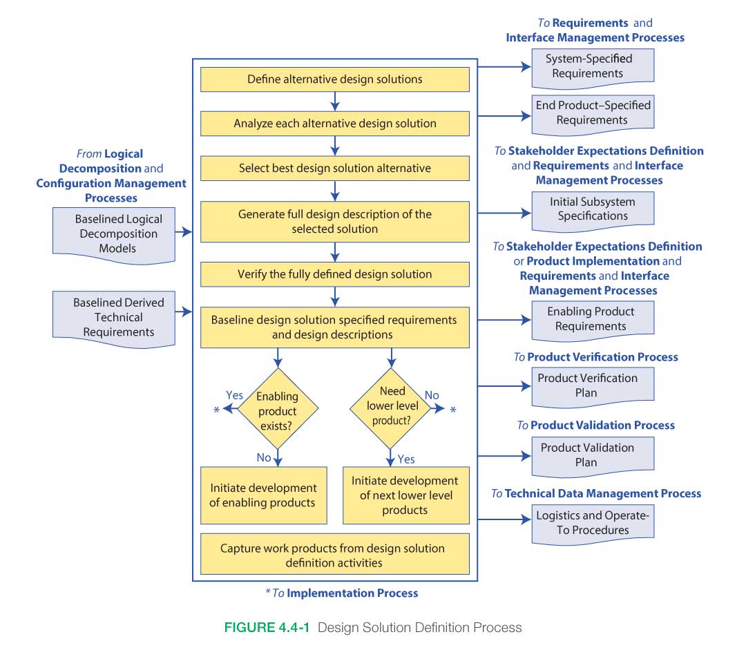
Figure 4.4-1 provides a typical flow diagram for the Design Solution Definition Process and identifies typical inputs, outputs, and activities to consider in addressing design solution definition.
4.4.1.1 Inputs
There are several fundamental inputs needed to initiate the Design Solution Definition Process:
- Technical Requirements: These are the customer and stakeholder needs that have been translated into a complete set of validated requirements for the system, including all interface requirements.
- Logical Decomposition Models: Requirements are analyzed and decomposed by one or more different methods (e.g., function, time, behavior, data flow, states, modes, system architecture, etc.) in order to gain a more comprehensive understanding of their interaction and behaviors. (See the definition of a model in Appendix B.)
4.4.1.2 Process Activities
4.4.1.2.1 Define Alternative Design Solutions
The realization of a system over its life cycle involves a succession of decisions among alternative courses of action. If the alternatives are precisely defined and thoroughly understood to be well differentiated in the cost-effectiveness space, then the systems engineer can make choices among them with confidence.
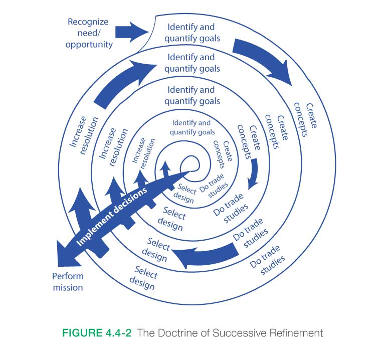
To obtain assessments that are crisp enough to facilitate good decisions, it is often necessary to delve more deeply into the space of possible designs than has yet been done, as illustrated in Figure 4.4-2. It should be realized, however, that this illustration represents neither the project life cycle, which encompasses the system development process from inception through disposal, nor the product development process by which the system design is developed and implemented.
Each “create concepts” step in Figure 4.4-2 involves a recursive and iterative design loop driven by the set of stakeholder expectations where a straw man architecture/design, the associated ConOps, and the derived requirements are developed and programmatic constraints such as cost and schedule are considered. These three products should be consistent with each other and will require iterations and design decisions to achieve this consistency. This recursive and iterative design loop is illustrated in Figure 4.0-1.
Each “create concepts” step in Figure 4.4-2 also involves an assessment of potential capabilities offered by the continually changing state of technology and potential pitfalls captured through experience-based review of prior program/project lessons learned data. It is imperative that there be a continual interaction between the technology development process, crosscutting processes such as human systems integration, and the design process to ensure that the design reflects the realities of the available technology and that overreliance on immature technology is avoided. Additionally, the state of any technology that is considered enabling should be properly monitored, and care should be taken when assessing the impact of this technology on the concept performance. This interaction is facilitated through a periodic assessment of the design with respect to the maturity of the technology required to implement the design. (See Section 4.4.2.1 in the NASA Expanded Guidance for Systems Engineering at https://nen.nasa.gov/web/se/doc-repository for a more detailed discussion of technology assessment.) These technology elements usually exist at a lower level in the PBS. Although the process of design concept development by the integration of lower level elements is a part of the systems engineering process, there is always a danger that the top-down process cannot keep up with the bottom-up process. Therefore, system architecture issues need to be resolved early so that the system can be modeled with sufficient realism to do reliable trade studies.
As the system is realized, its particulars become clearer—but also harder to change. See the rising “Cost to Change Design Direction” in Figure 2.5‑1. The purpose of systems engineering is to make sure that the Design Solution Definition Process happens in a way that leads to the most functional, safe, and cost-effective final system while working within any given schedule boundaries. The basic idea is that before those decisions that are hard to undo are made, the alternatives should be carefully and iteratively assessed, particularly with respect both to the maturity of the required technology and to stakeholder expectations for efficient, effective operations.
4.4.1.2.2 Create Alternative Design Concepts
Once it is understood what the system is to accomplish, it is possible to devise a variety of ways that those goals can be met. Sometimes, that comes about as a consequence of considering alternative functional allocations and integrating available subsystem design options, all of which can have technologies at varying degrees of maturity. Ideally, as wide a range of plausible alternatives as is consistent with the design organization’s charter should be defined, keeping in mind the current stage in the process of successive refinement. When the bottom-up process is operating, a problem for the systems engineer is that the designers tend to become fond of the designs they create, so they lose their objectivity; the systems engineer should stay an “outsider” so that there is more objectivity. This is particularly true in the assessment of the technological maturity of the subsystems and components required for implementation. There is a tendency on the part of technology developers and project management to overestimate the maturity and applicability of a technology that is required to implement a design. This is especially true of “heritage” equipment. The result is that critical aspects of systems engineering are often overlooked.
The creation of alternative design solutions involves assessment of potential capabilities offered by the continually changing state of technology. A continual interaction between the technology development process and the design process ensures that the design reflects the realities of the available technology. This interaction is facilitated through periodic assessment of the design with respect to the maturity of the technology required to implement the design.
After identifying the technology gaps existing in a given design concept, it is frequently necessary to undertake technology development in order to ascertain viability. Given that resources will always be limited, it is necessary to pursue only the most promising technologies that are required to enable a given concept.
If requirements are defined without fully understanding the resources required to accomplish needed technology developments, then the program/project is at risk. Technology assessment should be done iteratively until requirements and available resources are aligned within an acceptable risk posture. Technology development plays a far greater role in the life cycle of a program/project than has been traditionally considered, and it is the role of the systems engineer to develop an understanding of the extent of program/project impacts—maximizing benefits and minimizing adverse effects. Traditionally, from a program/project perspective, technology development has been associated with the development and incorporation of any “new” technology necessary to meet requirements. However, a frequently overlooked area is that associated with the modification of “heritage” systems incorporated into different architectures and operating in different environments from the ones for which they were designed. If the required modifications and/or operating environments fall outside the realm of experience, then these too should be considered technology development.
To understand whether or not technology development is required—and to subsequently quantify the associated cost, schedule, and risk—it is necessary to systematically assess the maturity of each system, subsystem, or component in terms of the architecture and operational environment. It is then necessary to assess what is required in the way of development to advance the maturity to a point where it can successfully be incorporated within cost, schedule, and performance constraints. A process for accomplishing this assessment is described in Appendix G. Because technology development has the potential for such significant impacts on a program/project, technology assessment needs to play a role throughout the design and development process from concept development through Preliminary Design Review (PDR). Lessons learned from a technology development point of view should then be captured in the final phase of the program.
On the first turn of the successive refinement in Figure 4.4-2, the subject is often general approaches or strategies, sometimes architectural concepts. On the next, it is likely to be functional design, then detailed design, and so on. The reason for avoiding a premature focus on a single design is to permit discovery of the truly best design. Part of the systems engineer’s job is to ensure that the design concepts to be compared take into account all interface requirements. Characteristic questions include: “Did you include the cabling?” or “Did you consider how the maintainers can repair the system?” When possible, each design concept should be described in terms of controllable design parameters so that each represents as wide a class of designs as is reasonable. In doing so, the systems engineer should keep in mind that the potentials for change may include organizational structure, personnel constraints, schedules, procedures, and any of the other things that make up a system. When possible, constraints should also be described by parameters.
4.4.1.2.3 Analyze Each Alternative Design Solution
The technical team analyzes how well each of the design alternatives meets the system objectives (technology gaps, effectiveness, technical achievability, performance, cost, schedule, and risk, both quantified and otherwise). This assessment is accomplished through the use of trade studies. The purpose of the trade study process is to ensure that the system architecture, intended operations (i.e., the ConOps) and design decisions move toward the best solution that can be achieved with the available resources. The basic steps in that process are:
- Devise some alternative means to meet the functional requirements. In the early phases of the project life cycle, this means focusing on system architectures; in later phases, emphasis is given to system designs.
- Evaluate these alternatives in terms of the MOPs and system life cycle cost. Mathematical models are useful in this step not only for forcing recognition of the relationships among the outcome variables, but also for helping to determine what the MOPs should be quantitatively.
- Rank the alternatives according to appropriate selection criteria.
- Drop less promising alternatives and proceed to the next level of resolution, if needed.
The trade study process should be done openly and inclusively. While quantitative techniques and rules are used, subjectivity also plays a significant role. To make the process work effectively, participants should have open minds, and individuals with different skills—systems engineers, design engineers, crosscutting specialty discipline and domain engineers, program analysts, system end users, decision scientists, maintainers, operators, and project managers—should cooperate. The right quantitative methods and selection criteria should be used. Trade study assumptions, models, and results should be documented as part of the project archives. The participants should remain focused on the functional requirements, including those for enabling products. For an in-depth discussion of the trade study process, see Section 6.8. The ability to perform these studies is enhanced by the development of system models that relate the design parameters to those assessments, but it does not depend upon them.
The technical team should consider a broad range of concepts when developing the system model. The model should define the roles of crew, operators, maintainers, logistics, hardware, and software in the system. It should identify the critical technologies required to implement the mission and should consider the entire life cycle from fabrication to disposal. Evaluation criteria for selecting concepts should be established. Cost is always a limiting factor. However, other criteria, such as time to develop and certify a unit, risk, and reliability, also are critical. This stage cannot be accomplished without addressing the roles of operators and maintainers. These contribute significantly to life cycle costs and to the system reliability. Reliability analysis should be performed based upon estimates of component failure rates for hardware and an understanding of the consequences of these failures. If probabilistic risk assessment models are applied, it may be necessary to include occurrence rates or probabilities for software faults or human error events. These models should include hazard analyses and controls implemented through fault management. Assessments of the maturity of the required technology should be done and a technology development plan developed.
Controlled modification and development of design concepts, together with such system models, often permits the use of formal optimization techniques to find regions of the design space that warrant further investigation.
Whether system models are used or not, the design concepts are developed, modified, reassessed, and compared against competing alternatives in a closed-loop process that seeks the best choices for further development. System and subsystem sizes are often determined during the trade studies. The end result is the determination of bounds on the relative cost-effectiveness of the design alternatives, measured in terms of the quantified system goals. (Only bounds, rather than final values, are possible because determination of the final details of the design is intentionally deferred.) Increasing detail associated with the continually improving resolution reduces the spread between upper and lower bounds as the process proceeds.
4.4.1.2.4 Select the Best Design Solution Alternative
The technical team selects the best design solution from among the alternative design concepts, taking into account subjective factors that the team was unable to quantify, such as robustness, as well as estimates of how well the alternatives meet the quantitative requirements; the maturity of the available technology; and any effectiveness, cost, schedule, risk, or other constraints.
The Decision Analysis Process, as described in Section 6.8, should be used to make an evaluation of the alternative design concepts and to recommend the “best” design solution.
When it is possible, it is usually well worth the trouble to develop a mathematical expression, called an “objective function,” that expresses the values of combinations of possible outcomes as a single measure of cost-effectiveness, as illustrated in Figure 4.4-3, even if both cost and effectiveness should be described by more than one measure.

Note: The different shaded areas indicate different levels of uncertainty. Dashed lines represent constant values of objective function (cost-effectiveness). Higher values of cost-effectiveness are achieved by moving toward upper left. A, B, and C are design concepts with different risk patterns.
The objective function (or “cost function”) assigns a real number to candidate solutions or “feasible solutions” in the alternative space or “search space.” A feasible solution that minimizes (or maximizes, if that is the goal) the objective function is called an “optimal solution.” When achievement of the goals can be quantitatively expressed by such an objective function, designs can be compared in terms of their value. Risks associated with design concepts can cause these evaluations to be somewhat nebulous because they are uncertain and are best described by probability distributions.
In Figure 4.4-3, the risks are relatively high for design concept A. There is little risk in either effectiveness or cost for concept B, while the risk of an expensive failure is high for concept C, as is shown by the cloud of probability near the x axis with a high cost and essentially no effectiveness. Schedule factors may affect the effectiveness and cost values and the risk distributions.
The mission success criteria for systems differ significantly. In some cases, effectiveness goals may be much more important than all others. Other projects may demand low costs, have an immutable schedule, or require minimization of some kinds of risks. Rarely (if ever) is it possible to produce a combined quantitative measure that relates all of the important factors, even if it is expressed as a vector with several components. Even when that can be done, it is essential that the underlying actors and relationships be thoroughly revealed to and understood by the systems engineer. The systems engineer should weigh the importance of the unquantifiable factors along with the quantitative data.
Technical reviews of the data and analyses, including technology maturity assessments, are an important part of the decision support packages prepared for the technical team. The decisions that are made are generally entered into the configuration management system as changes to (or elaborations of) the system baseline. The supporting trade studies are archived for future use. An essential feature of the systems engineering process is that trade studies are performed before decisions are made. They can then be baselined with much more confidence.
4.4.1.2.5 Increase the Resolution of the Design
The successive refinement process of Figure 4.4-2 illustrates a continuing refinement of the system design. At each level of decomposition, the baselined derived (and allocated) requirements become the set of high-level requirements for the decomposed elements, and the process begins again. One might ask, “When do we stop refining the design?” The answer is that the design effort proceeds to a depth that is sufficient to meet several needs: the design should penetrate sufficiently to allow analytical validation of the design to the requirements and ConOps; it should also have sufficient depth to support cost and operations modeling and to convince a review team of a feasible design with performance, cost, and risk margins.
The systems engineering engine is applied again and again as the system is developed. As the system is realized, the issues addressed evolve and the particulars of the activity change. Most of the major system decisions (goals, architecture, acceptable life cycle cost, etc.) are made during the early phases of the project, so the successive refinements do not correspond precisely to the phases of the system life cycle. Much of the system architecture can be seen even at the outset, so the successive refinements do not correspond exactly to development of the architectural hierarchy either. Rather, they correspond to the successively greater resolution by which the system is defined.
It is reasonable to expect the system to be defined with better resolution as time passes. This tendency is formalized at some point (in Phase B) by defining a baseline system definition. Usually, the goals, objectives, and constraints are baselined as the requirements portion of the baseline. The entire baseline is then placed under configuration control in an attempt to ensure that any subsequent changes are indeed justified and affordable.
At this point in the systems engineering process, there is a logical branch point. For those issues for which the process of successive refinement has proceeded far enough, the next step is to implement the decisions at that level of resolution. For those issues that are still insufficiently resolved, the next step is to refine the development further.
4.4.1.2.6 Fully Describe the Design Solution
Once the preferred design alternative has been selected and the proper level of refinement has been completed, then the design is fully defined into a final design solution that will satisfy the technical requirements and ConOps. The design solution definition will be used to generate the end product specifications that will be used to produce the product and to conduct product verification. This process may be further refined depending on whether there are additional subsystems of the end product that need to be defined.
The scope and content of the full design description should be appropriate for the product life cycle phase, the phase success criteria, and the product position in the PBS (system structure). Depending on these factors, the form of the design solution definition could be simply a simulation model or a paper study report. The technical data package evolves from phase to phase, starting with conceptual sketches or models and ending with complete drawings, parts list, and other details needed for product implementation or product integration. Typical output definitions from the Design Solution Definition Process are shown in Figure 4.4-1 and are described in Section 4.4.1.3.
4.4.1.2.7 Verify the Design Solution
Once an acceptable design solution has been selected from among the various alternative designs and documented in a technical data package, the design solution should next be verified against the system requirements and constraints. A method to achieve this verification is by means of a peer review to evaluate the resulting design solution definition. Guidelines for conducting a peer review are discussed in Section 6.7.2.4.5.
In addition, peer reviews play a significant role as a detailed technical component of higher level technical and programmatic reviews. For example, the peer review of a component battery design can go into much more technical detail on the battery than the integrated power subsystem review. Peer reviews can cover the components of a subsystem down to the level appropriate for verifying the design against the requirements. Concerns raised at the peer review might have implications on the power subsystem design and verification and therefore should be reported at the next higher level review of the power subsystem.
The verification should show that the design solution definition:
- Is realizable within the constraints imposed on the technical effort;
- Has specified requirements that are stated in acceptable statements and have bidirectional traceability with the technical requirements and stakeholder expectations; and
- Has decisions and assumptions made in forming the solution consistent with its set of technical requirements and identified system product and service constraints.
This design solution verification is in contrast to the verification of the end product described in the end product verification plan which is part of the technical data package. That verification occurs in a later life cycle phase and is a result of the Product Verification Process (see Section 5.3) applied to the realization of the design solution as an end product.
4.4.1.2.8 Validate the Design Solution
The validation of the design solution is a recursive and iterative process as shown in Figure 4.0-1. Each alternative design concept is validated against the set of stakeholder expectations. The stakeholder expectations drive the iterative design loop in which a straw man architecture/design, the ConOps, and the derived requirements are developed. These three products should be consistent with each other and will require iterations and design decisions to achieve this consistency. Once consistency is achieved, functional analyses allow the study team to validate the design against the stakeholder expectations. A simplified validation asks the questions: Does the system work as expected? How does the system respond to failures, faults, and anomalies? Is the system affordable? If the answer to any of these questions is no, then changes to the design or stakeholder expectations will be required, and the process is started over again. This process continues until the system—architecture, ConOps, and requirements—meets the stakeholder expectations.
This design solution validation is in contrast to the validation of the end product described in the end-product validation plan, which is part of the technical data package. That validation occurs in a later life cycle phase and is a result of the Product Validation Process (see Section 5.4) applied to the realization of the design solution as an end product.
4.4.1.2.9 Identify Enabling Products
Enabling products are the life cycle support products and services (e.g., production, test, deployment, training, maintenance, and disposal) that facilitate the progression and use of the operational end product through its life cycle. Since the end product and its enabling products are interdependent, they are viewed as a system. Project responsibility thus extends to responsibility for acquiring services from the relevant enabling products in each life cycle phase. When a suitable enabling product does not already exist, the project that is responsible for the end product can also be responsible for creating and using the enabling product.
Therefore, an important activity in the Design Solution Definition Process is the identification of the enabling products and personnel that will be required during the life cycle of the selected design solution and then initiating the acquisition or development of those enabling products and personnel. Need dates for the enabling products should be realistically identified on the project schedules, incorporating appropriate schedule slack. Then firm commitments in the form of contracts, agreements, and/or operational plans should be put in place to ensure that the enabling products will be available when needed to support the product life cycle phase activities. The enabling product requirements are documented as part of the technical data package for the Design Solution Definition Process.
An environmental test chamber is an example of an enabling product whose use would be acquired at an appropriate time during the test phase of a space flight system.
Special test fixtures or special mechanical handling devices are examples of enabling products that would have to be created by the project. Because of long development times as well as oversubscribed facilities, it is important to identify enabling products and secure the commitments for them as early in the design phase as possible.
4.4.1.2.10 Baseline the Design Solution
As shown earlier in Figure 4.0-1, once the selected system design solution meets the stakeholder expectations, the study team baselines the products and prepares for the next life cycle phase. Because of the recursive nature of successive refinement, intermediate levels of decomposition are often validated and baselined as part of the process. In the next level of decomposition, the baselined requirements become the set of high-level requirements for the decomposed elements, and the process begins again.
Baselining a particular design solution enables the technical team to focus on one design out of all the alternative design concepts. This is a critical point in the design process. It puts a stake in the ground and gets everyone on the design team focused on the same concept. When dealing with complex systems, it is difficult for team members to design their portion of the system if the system design is a moving target. The baselined design is documented and placed under configuration control. This includes the system requirements, specifications, and configuration descriptions.
While baselining a design is beneficial to the design process, there is a danger if it is exercised too early in the Design Solution Definition Process. The early exploration of alternative designs should be free and open to a wide range of ideas, concepts, and implementations. Baselining too early takes the inventive nature out of the concept exploration. Therefore, baselining should be one of the last steps in the Design Solution Definition Process.
4.4.1.3 Outputs
Outputs of the Design Solution Definition Process are the specifications and plans that are passed on to the product realization processes. They contain the design-to, build-to, train-to, and code-to documentation that complies with the approved baseline for the system.
As mentioned earlier, the scope and content of the full design description should be appropriate for the product life cycle phase, the phase success criteria, and the product position in the PBS.
Outputs of the Design Solution Definition Process include the following:
- The System Specification: The system specification contains the functional baseline for the system that is the result of the Design Solution Definition Process. The system design specification provides sufficient guidance, constraints, and system requirements for the design engineers to begin developing the design.
- The System External Interface Specifications: The system external interface specifications describe the functional baseline for the behavior and characteristics of all physical interfaces that the system has with the external world. These include all structural, thermal, electrical, and signal interfaces, as well as the human-system interfaces.
- The End-Product Specifications: The end-product specifications contain the detailed build-to and code-to requirements for the end product. They are detailed, exact statements of design particulars, such as statements prescribing materials, dimensions, and quality of work to build, install, or manufacture the end product.
- The End-Product Interface Specifications: The end-product interface specifications contain the detailed build-to and code-to requirements for the behavior and characteristics of all logical and physical interfaces that the end product has with external elements, including the human-system interfaces.
- Initial Subsystem Specifications: The end-product subsystem initial specifications provide detailed information on subsystems if they are required.
- Enabling Product Requirements: The requirements for associated supporting enabling products provide details of all enabling products. Enabling products are the life cycle support products, infrastructures, personnel, logistics, and services that facilitate the progression and use of the operational end product through its life cycle. They are viewed as part of the system since the end product and its enabling products are interdependent.
- Product Verification Plan: The end-product verification plan (generated through the Technical Planning Process) provides the content and depth of detail necessary to provide full visibility of all verification activities for the end product. Depending on the scope of the end product, the plan encompasses qualification, acceptance, prelaunch, operational, and disposal verification activities for flight hardware and software.
- Product Validation Plan: The end-product validation plan (generated through the Technical Planning Process) provides the content and depth of detail necessary to provide full visibility of all activities to validate the end product against the baselined stakeholder expectations. The plan identifies the type of validation, the validation procedures, and the validation environment that are appropriate to confirm that the realized end product conforms to stakeholder expectations.
- Logistics and Operate-to Procedures: The applicable logistics and operate-to procedures for the system describe such things as handling, transportation, maintenance, long-term storage, and operational considerations for the particular design solution.
Other outputs may include:
- Human Systems Integration Plan: The system HSI Plan should be updated to indicate the numbers, skills, and development (i.e., training) required for humans throughout the full life cycle deployment and operations of the system.
4.4.2 Design Solution Definition Guidance
Refer to Section 4.4.2 in the NASA Expanded Guidance for Systems Engineering at https://nen.nasa.gov/web/se/doc-repository for additional guidance on:
- technology assessment,
- human capability assessment, and
- integrating engineering specialties into the SE process.