


12.0 GROUND ASSEMBLY DESIGN AND EMERGENCY EGRESS OPERATIONS
This section focuses on the design of spaceflight systems, hardware, and equipment that are accessed, used, or interfaced in some way by personnel other than the spaceflight crews (e.g., ground support personnel) during preflight ground processing, launch, landing, recovery, contingency, and ground emergency egress operations.
12.1 Ground Assembly Design
This section focuses on the design of spaceflight systems, hardware, and equipment that are accessed, used, or interfaced in some way by personnel other than just the spaceflight crews (e.g., ground support personnel). Spaceflight systems include those systems that support crew launch, orbit, transit, surface ops, return, and recovery. Ground support personnel perform numerous tasks utilizing spaceflight systems, hardware, and equipment at times other than during spaceflight such as during ground operations before launches and after landings. Incapable, incomplete, or improper performance of tasks and/or improper use of hardware and equipment by the ground support personnel could lead to LOM or LOC of the spaceflight crew.
The requirements in this section ensure that the capabilities and needs of the ground processing crew are considered during the design and development of the flight system along with ensuring that the flight system is not compromised during the assembly, test, and operational phases.
The requirements listed in section 12.1 of this NASA Technical Standard apply only to the design and development of flight systems interfaced by ground support personnel at integration, launch, landing, recovery, and deservicing sites. These requirements are optional for designs at manufacturing and development sites.
This section is applicable for the following: when NASA is performing the ground processing for vehicles built by non-NASA vendors or when one vendor builds the vehicle and a second vendor is responsible for the assembly, integration, and maintenance. If one vendor is responsible for the design, assembly, and maintenance, then this section does not apply.
12.1.1 System Assumptions
[V2 12003] Each human spaceflight program shall document the system support design and environment:
- Work environment (e.g., lighting, heating, atmosphere, gravity)
- Tools and support equipment
- Ground support personnel characteristics (e.g., size, training, experience, number, physical and cognitive capabilities, skills, ergonomics)
- Ground support personnel tasks (e.g., environment, complexity, scheduling)
[Rationale: A separate support system (i.e., facilities, equipment, personnel, procedures) is required to support the spaceflight system. The two systems must work together so that the spaceflight system can achieve its performance goals. The spaceflight system developer may not be in control of the support system; but to properly design the spaceflight system, the developer must have a clear understanding of the support system, including its functions and users.]
12.1.2 Ground Support Personnel Accommodation
12.1.2.1 Anthropometry, Biomechanics, Range of Motion, and Strength
[V2 12004] Each program shall identify an anthropometry, biomechanics, range of motion, and strength data set for the ground support population to be accommodated in support of all requirements in this section of this NASA Technical Standard.
[Rationale: Ground support personnel anthropometry, reach, biomechanics, range of motion, and strength need to be defined for the program in a data set. Ground support personnel data sets may represent different populations than spaceflight crew. Systems need to accommodate the physical capabilities and limitations of ground support personnel to allow for required servicing, maintenance, assembly, testing, or operational use by ground support personnel (e.g., rescue, flight test, special docking). Systems architecture and vehicle layout and tasks must not force ground support personnel to move, twist, or stretch into awkward positions. Tasks that require awkward positioning can increase the likelihood of errors or injury.]
12.1.2.2 Protective Equipment
[V2 12005] The system shall accommodate ground personnel protective equipment and attire.
[Rationale: The design must accommodate for ground personnel functions constrained or increased by protective equipment or combinations of such (e.g., pressurized or unpressurized suits, breathing hoses or air packs, gloves, fall protection harnesses, masks, hats or helmets, sensors, cords). Protective equipment often limits human capabilities (e.g., visual envelope, range of motion, reach envelope, audio, communication, grasp) and often increases personnel work volumes or quantity of personnel anticipated (e.g., pressurized suited tasks often require a minimum of two personnel and air packs or hoses). Design factors for audio, communication, displays, and control systems must accommodate for face, ear, and/or hand protection (e.g., larger knobs, increased volume, larger tactile surfaces, resistive touchscreens). Integrated task analysis must be performed to identify designs or functions that may be affected by protective equipment or attire. Physical characteristics of protective equipment need to be provided to designers so the protective equipment can be accommodated in system design.]
12.1.2.3 Volume Accommodation
[V2 12006] The system shall provide the volume necessary for the ground support personnel to perform all ground processing tasks using the required tools and equipment.
[Rationale: The physical work envelopes must accommodate full or partial access for the expected number of ground support personnel, equipment required to perform the task, and any associated protective equipment. The volume must also accommodate body, work, reach, visual, tool, and protective equipment envelopes to accomplish the task. The physical work envelopes of doors, hatches, and entryways must consider further volumetric restrictions imposed by ground processing, including door/hatch masses and hinges, if captive, actuators, or other entry mechanisms along with air ducts, cords, sensors, protective covers, safety equipment, portable lighting, and potential mechanical assist devices (e.g., personnel and equipment entry platforms, lift devices). For safe passage, timeliness, and to prevent collateral damage, hatches and ingress/egress openings must be large enough for the ground support personnel to pass safely and efficiently in situations involving suited personnel, transporting equipment or hardware through the opening, emergency or contingency operations, or incapacitated personnel rescue.]
12.1.2.4 Ground Processing – Induced Forces
[V2 12007] Systems, hardware, and equipment shall be protected from or be capable of withstanding forces imposed by the ground support personnel or ground support equipment (GSE), in a 1-g environment.
[Rationale: Either by vehicle design (preferred) or through other means (e.g., labels, placards, covers, training, walking platforms, procedures), the spaceflight system needs to be protected from the forces imposed by ground support personnel (and their associated equipment) while performing vehicle tasks. Furthermore, any accessible items that could be inappropriately used such as handles, steps, handrails, or mobility aids are to be either designed to withstand the forces imposed by the ground support personnel or be clearly labeled as a keep-out zone. Historical experience with Shuttle and ISS has shown that it is important to make it clear which parts of a vehicle may not be used as handles, steps, or handrails so that ground support and spaceflight crews do not inadvertently damage delicate portions of the vehicle. Priority is given to areas where ground support and spaceflight crews will traverse and /or work most frequently and those areas with the most severe potential hazard consequences.]
12.1.2.5 Systems Accessibility
[V2 12008] System components, hardware, and/or equipment that requires ground support personnel inspection or interaction shall be accessible.
[Rationale: Ground support personnel must be able to access system components, hardware, or equipment that requires inspection or interaction. Consideration needs to be given for type of access and inspection (e.g., physical and visual) needed for each component, hardware, and equipment during vehicle design. Proximity and envelope required for the access and inspection is defined by the function.]
12.1.2.6 Tool Clearance
[V2 12009] The system shall provide tool clearances for tool installation and actuation for all tool interfaces during ground processing.
[Rationale: The required tool clearance for fit and actuation is to be determined and applied to the design of hardware. Consideration needs to be given to type of tool, the user’s hand action, the tool’s motion envelope and forces needed, the user population hand anthropometric data, adjacent equipment, the inclusion and use of appropriate shields/guards/gloves, and the need for tool tethering when determining the minimum clearance dimensions.]
12.1.3 Hardware and Software Design to Support Ground Operations
12.1.3.1 Flight Hardware Differentiation
[V2 12010] Flight system components that have the same or similar form, but different functions shall not be physically interchangeable.
[Rationale: Components requiring installation (including, but not limited to, Line Replacement Units (LRUs)) that are not interchangeable functionally will not be interchangeable physically. This requirement addresses installation of a component in the wrong location. While some installable units may be used for the same function in multiple instances (e.g., redundant strings), many may be physically similar but functionally distinct. In such cases, installation in the wrong location could result in damage to the hardware or to the system into which it is inserted. This requirement is intended to preclude such installation in the wrong location. Physical designs may include incompatible bolt patterns, pin/hole alignment, and/or baseplate differences that do not allow incorrect and/or inadvertent location installation. In addition to differentiation, labeling to show distinctions is also applied.]
12.1.3.2 Hardware Protection
[V2 12011] The system shall provide a means of protecting flight hardware and equipment from damage during ground processing.
[Rationale: Equipment that can reasonably sustain damage during ground processing must have a means of being protected during ground operations (e.g., window covers, wire covers, propulsion line covers). Note that removable Ground Support Equipment can be used to accomplish this goal.]
12.1.3.3 Mobility Aids
[V2 12012] The system shall provide mobility aids to support expected ground support personnel tasks.
[Rationale: Mobility aids such as handholds allow ground support personnel to safely and efficiently move from one location to another, preventing inadvertent damage to equipment. Required tasks will need to be determined by task analysis, which will include the identification of mobility aids.]
12.1.3.4 Equipment Handling Design
[V2 12013] All items designed to be carried, supported, or removed and replaced shall have a means for grasping, handling, and carrying.
[Rationale: This requirement is intended to avoid damage to flight hardware and to prevent injury to ground support personnel. Items that are unable to be reasonably moved may incur injury to ground support personnel or damage to the flight systems if handled inappropriately. Flight items that must be moved may be damaged if handled inappropriately. Damage to flight hardware and injury to the ground support personnel can result from poor grips on a nonhandle protrusion or from protrusions that do not hold the weight of the hardware. Non-handle protrusions can break and lead to dropping flight hardware. Handles or handholds need to be designed to support the weight of the hardware, any lifting mechanisms, accommodate bare or gloved hands where appropriate, be non-slip, and/or be clearly labeled.]
12.1.3.5 Inadvertent Operation Prevention
[V2 12014] The system shall be designed to prevent inadvertent operation of controls during ground processing.
[Rationale: The system needs to be designed to preclude inadvertent operation. For example, accidental activation by contact can be prevented by the use of guards, covers, and physical separation from other controls. Accidental activation of commands can be prevented with an “arm-fire” mechanism. Two-step commanding allows for ground support personnel confirmation before completing critical, hazardous, or destructive commands. Controls need to be spaced to prevent inadvertent actuation of adjacent switches. For example, hard plastic, molded covers may be placed over contact-sensitive items, covers placed over adjacent switches, or metal foot and handholds may be added to assure only applicable steps are executed.]
12.1.3.6 Incorrect Installation Prevention
[V2 12015] System hardware and equipment shall be designed to prevent incorrect mounting or installation.
[Rationale: This requirement is intended to assure that fasteners are inserted in the correct holes, brackets are attached in the correct location, connectors are installed in the correct position, etc. Improperly mounting equipment during ground processing will result in unsafe conditions for spaceflight crews and increase the risk of LOC/LOM events through damage to hardware or changes in configuration during launch and ascent. Physical features to prevent incorrect mounting or installation largely prevent these situations. Examples of physical features include supports, guides, size or shape differences, fastener locations, and alignment pins. Physical features are the first line of defense for preventing such errors. In addition to physical features, labeling or marking mitigates human error. Visual indication might include any marking on or adjacent to the hardware/equipment interface, labels, or color coding that provides information about mounting. Unique labeling of hardware/equipment provides an indication that the item to be mounted and the mounting location match. Labels provide contextual information to help assure that the ground support personnel do not attempt to install a hardware item incorrectly; such an attempt could damage the hardware or the interfaces on the vehicle.]
12.1.3.7 Pre-Defined Tool Set
[V2 12016] The system shall be designed to be assembled, prepared for launch, maintained, and reconfigured using a pre-defined set of standard tools and lesser set of any pre-established set of specialized tools.
[Rationale: Establishing a minimal set of tools for pre- and post-mission processing of flight hardware requires integration across spaceflight systems, hardware, and equipment designs. The goal is to have an integrated set of tools (across systems or programs) that can be used for all ground processing tasks, using common tools wherever possible. Defined toolsets would reduce the number and types of tools and subsequently reduce the number and types of fasteners. Minimizing the variations and quantity within the tool set reduces training time, processing time, potential damage to hardware and injury to personnel, and decreases the chance of using the wrong tool for the task. System designs and tool determinations must accommodate tool reach, grasps, and volumes of ground personnel populations, tool motions, and any concurrent flight system component volume needed around the tool use. For example, designs should account for tools being used by one person while adjacent personnel assist in securing the weight or positioning of a removable or tested component. Tool grasps, weights, tethering, and clearance may also be affected by varying postures needed for access or visibility. Integrated task analyses are performed to support use of common tools or determine where specialized tools may need to be pre-defined.]
12.1.3.8 Captive Fasteners
[V2 12017] Fasteners on installable units shall be captive.
[Rationale: A captive fastener is one that is automatically retained in a work piece when it is not performing its load-bearing job. Captive fasteners for maintenance, assembly, integration, and processing tasks, therefore, do not require ground support personnel to restrain and store them during task performance, and can more easily be installed with one hand, reducing task times and reducing the chance of fastener loss. Dropped fasteners could become Foreign Object Debris (FOD), which pose a risk during the mission. They can cause injury, impact launch schedule, and damage equipment.]
12.1.3.9 Ground Processing Without Damage
[V2 12018] The system shall be designed for assembly, testing and checkout, troubleshooting, and maintenance that prevents damage to other components.
[Rationale: Damage to certified flight components will cause costly recertification and may impact the launch. This requirement is intended to limit such damage and recertification by maintaining a flight configuration for all systems that are not part of the maintenance activity and providing mitigation strategies when possible. To define the necessary accommodations for maintenance without damage, an integrated task analysis must be performed for each maintenance activity. Methods that have been successfully used to preclude damaging other components during maintenance include the following: (1) routing cables to prevent mechanical damage, pinching by doors, or twisting; (2) protecting against inadvertent actuation; and (3) implementing provisions for components that are susceptible to abuse or those frequently used.]
12.1.3.10 Replaceable Items
[V2 12019] The system shall locate maintenance items so that a planned ground processing or corrective or preventive maintenance task does not require the deintegration or demating of other systems or components.
[Rationale: Deintegration of certified flight components will cause costly recertification if disturbed. This requirement is intended to limit damage and recertification by maintaining a flight configuration of all systems and providing mitigation strategies when possible. Corrective maintenance is limited to LRUs, whereas preventive maintenance is a planned maintenance activity (e.g., battery replacement). To define the necessary accommodations for maintenance without damage, an integrated task analysis must be performed for each maintenance activity.]
12.1.3.11 Visual Access for Ground Processing
[V2 12020] The system shall provide direct line-of-sight visual access to all flight system components requiring inspections or other human-system interactions, except self-mating connectors, on which ground processing is performed by ground personnel.
[Rationale: Direct line-of-sight visual access reduces the likelihood of human error that can occur when blind (by feel) operations or operations requiring the use of specialized tools (e.g., mirrors or bore scopes) are performed. The addition of obstructions from the hands, tools, equipment, PPE (e.g., gloves, protective suits), corrective lenses, and the components or cabling needs to be considered during the line-of-sight operation. Reliance on just the “feel” of the hardware introduces human error variances. A self-mating connector is a connector that, when two pieces of hardware slide into place, they automatically self-mate. See requirement [V2 12014] Inadvertent Operation Prevention.]
12.1.3.12 Lighting
[V2 12021] The flight system in combination with ground support equipment shall provide lighting to perform ground processing tasks in the vehicle.
[Rationale: Lighting is required to ensure that the ground support personnel can adequately view the hardware/equipment associated with the task, and it is generally accomplished through GSE but may include flight lighting. Additionally, this may require an integrated solution, utilizing the flight vehicle and ground equipment providers. Lighting or illumination types, levels, controls, selection, and design factors are to accommodate general assembly or bench work tasks down to extra fine precision while accounting for lux or lumen levels, shadow prevention, indirect and direct glare mitigations, color temperature, brightness adjustability, dark adaptation, color rendering, and lighting color techniques (e.g., red flood, low-color temperature, bright markings [foot-lamberts]). Variations in operating conditions such as natural sunlight, artificial lighting, or filtering must also be considered.]
12.1.3.13 Supplemental Systems
[V2 12022] The system shall be designed to support any supplemental systems that are required to assist ground support personnel when an assigned task cannot reliably, safely, or effectively be performed by ground support personnel alone.
[Rationale: Tasks that cannot be reliably, safely, or efficiently performed by the ground support personnel are to be identified. In those cases, supplemental systems (such as GSE) will need to be accommodated in design. This may include providing attach points for GSE, rails, tracking or removal guides, and/or accommodation of ground support lighting.]
12.1.3.14 Operational Consistency
[V2 12023] The system shall be designed for consistent operation across ground processing tasks.
[Rationale: The intent of this requirement is to ensure commonality and consistency across flight systems. This will facilitate learning and minimize interface-induced ground support personnel error. Examples include consistent use of control direction (“on” is always “up”), “closed” direction is always the same (right), consistent use of a release mechanism, terminology, markings, color coding, etc.]
12.1.3.15 Restraints and Platforms
[V2 12024] The system shall accommodate restraint and platform placement that ensures the reach and work envelope of the suited or unsuited ground support personnel for the required tasks.
[Rationale: Restraints and platforms are intended to keep personnel from falling (or related hazards), allow for hardware access, and protect the hardware from inadvertent ground support personnel collision. A task analysis will identify locations where restraints and platforms are needed. A worksite analysis will inform the placement and design the restraints and platforms needed.]
12.1.3.16 System Feedback
[V2 12025] The system shall provide feedback to the operator indicating successful task completion.
[Rationale: Feedback can include visual indication, audible click, handle position, bolt height, alert, etc. Feedback at task completion is important to prevent continual inputs into the system, which may lead to damage to the system. For example, when filling a tank, feedback that the tank is full is important to prevent overfilling, which may result in human injury or hardware/equipment damage. If system feedback is not possible, another means of feedback is necessary (i.e., GSE). For example, if the system does not provide indication of a full tank, the equipment used to fill the tank can provide the feedback.]
12.1.3.17 Stowage Access
[V2 12026] The system shall provide access for ground support personnel to spacecraft stowage volumes that require late loading and early unloading of items.
[Rationale: Ground personnel are responsible for any “late loading” of items such as fresh food, pharmaceuticals, and experiment items with short lifetimes that need to be placed onboard the spacecraft within 24 hours of launch. Similarly, “early access” items need to be retrieved off the spacecraft within a short time after landing. Regular unloading requires waiting until the spacecraft returns to the processing facility, which could be weeks later. The intent of this requirement is to allow the ground support personnel to perform these access operations safely without disruption to the spaceflight crew or spacecraft.]
12.1.3.18 Flight Software Systems
[V2 12027] The system shall allow the ground support personnel safe operation of flight software systems for ground processing.
[Rationale: Ground support personnel may be required to access flight software systems during ground operations tasks. Therefore, it is critical for flight software systems to have a mode or configuration for safe operation by ground support personnel.]
12.1.4 Safety
12.1.4.1 Sharp Edge and Burr Injury Prevention
[V2 12028] The system shall protect ground support personnel from injury resulting from sharp edges and burrs.
[Rationale: Protection of ground support personnel from injury controls ground operations costs by assuring that bodily fluids, such as blood, do not contaminate flight systems, degrading flight safety. In those areas that the ground support personnel would access for ground processing and maintenance, the design must protect them from burrs, sharp edges, and sharp corners. Support personnel may have an additional risk that system hardware may be in a more exposed configuration during maintenance or installation/removal operations. The intent of this requirement is for a design solution, not an operational solution, since the latter results in expensive recurring costs. The requirement may be met by rounding of edges and corners, sanding burrs, or by designing flight structure that hides sharp edges and corners and burrs from ground personnel during planned operations. It cannot be met by design of remove-before-flight protective structure.]
12.1.4.2 Pinch Point Prevention
[V2 12029] The system shall be designed to protect ground personnel from injury due to pinch points.
[Rationale: A pinch point can cause injury to ground personnel or damage to hardware if not protected. Pinch points may exist for the nominal function of equipment (i.e., equipment panels), but need to be covered or protected during ground operations. Injury may be avoided by locating pinch points out of the reach of the ground personnel or providing guards to eliminate the potential to cause injury.]
12.1.4.3 Hazard Controls
[V2 12030] The system shall be designed to prevent unnecessary exposure of ground support personnel and equipment to hazards, including spills, electrical shocks, and the release of stored energy.
[Rationale: Ground support personnel must not be exposed to hazards unnecessarily. Spill hazards can be avoided by capturing the spill or by adding extensions to the flight vehicle to relocate the hose to flight connection away from the vehicle. Electrical exposure can be avoided by shielding, interlocks, and de-energizing electrical stored energy. Interlocks must not be the sole mean of de-energizing electrical circuits of equipment and are not substitutes for lockout and tag-out procedures and practice.]
12.1.4.4 System Safing for Ground Operations
[V2 12031] The system shall alert and allow ground personnel to safe the system before performing any ground operation.
[Rationale: Elements or systems must provide methods for system safing during ground assembly and maintenance activities to protect the system, hardware, and equipment from damage or personnel from injury. To ensure all areas in which a method is to be in place for system safing, an integrated task analysis must be performed. The system must alert ground personnel of unsafe conditions. To safe or unsafe a system, a combination of mechanical actuation (physical lockout) with corresponding indicators (tagout means) allows ground personnel to engage or disengage the system while informing personnel of safe or unsafe conditions (e.g., flashing or steady lights of various colors, distinct audio alarms, positive locking engagements, other status indicators using multiple modalities). Safing or unsafing mechanisms and controls must be accessible to ground personnel for safe and timely execution. Methods that have been successfully used as controls for system safing include physical protection, interlocks, software disabling or multiple key combinations, cut-out switches, warning placards, and guards.]
12.1.4.5 Contamination Controls
[V2 12032] The system shall have controls in place to prevent the introduction of contaminants to the flight vehicle.
[Rationale: Elements or systems cannot release hazardous or non-hazardous materials into the spaceflight system during maintenance activities. Controls must be designed to prevent contamination.]
12.1.4.6 Containment of Fluids and Gases
[V2 12033] The system shall provide for containment and disposal of fluids and gases inadvertently released into the flight system.
[Rationale: This can be accomplished by isolating, draining, or venting pressurized fluids. System developers are to identify the containment points and create isolation capabilities. The control valves are to be located near those service points to avoid control errors.]
12.1.4.7 Safe Weight Limit
[V2 12034] Hardware and equipment installed or removed by ground support personnel without ground support equipment shall be less than a safe weight limit.
[Rationale: Handling of hardware and equipment that is too heavy can result in injury or damage to the equipment (e.g., dropped hardware). NIOSH has published a lifting equation, designed to determine a recommended weight limit for safely lifting loads. It accounts for factors that would affect a person’s ability to lift, including the position of the load relative to the body, the distance lifted, the frequency of lifts, and the coupling (gripping) method. These various factors need to be accounted for while determining safe weight limits for the ground support personnel during assembly, processing, and maintenance tasks. Other factors such as obstructions, surrounding environment, and the carefulness needed in placing an object is also considered in design.]
12.1.4.8 Safe Flight System Component Arrangement
[V2 12035] Flight system components shall be arranged, or located to prevent hazards, interference, or errors during concurrent ground processing tasks.
[Rationale: Hardware, personnel, software, and/or automation could interact in such a way during concurrent tasks as to create undesired outcomes. For example, crossing cables during installation may lead to inadvertent forces on those cables which may cause problems in-flight. The system and components must provide a means of damage detection by inspection or test and a means to recover. Consequences of errors on safety or system performance must be made clear. Placing items in view on system mold lines, rather than stacked or hidden, can provide visual indicators of damage or interferences. Obtaining a test failure must indicate the isolated area of the fault, and the system provides physical and visual means to the affected area. For pneumatic systems, clear sight glasses have been incorporated showing mechanical indicators to clearly identify performance flow or inoperability. In software or instrumentation, system status windows with conditional indicators for online, offline, optimal, or off nominal, can provide means of detecting the failure or damage in time to recover before flight.]
12.1.5 Connectors
12.1.5.1 Connector Design and Spacing
[V2 12036] Connectors shall be designed and spaced to allow for accurate, damage-free mating and demating by ground support personnel.
[Rationale: Connectors need to be grasped firmly for connecting and disconnecting. The clothing, gloves, equipment, and PPE worn by the ground support personnel during the task must be considered in design.]
12.1.5.2 Connector Incorrect Mating Prevention
[V2 12037] Connectors shall have physical features to preclude incorrect mating and mismating. This can be accomplished by differing connector shell sizes, differing connector keyway arrangements, and having different contact arrangements (these are listed in order of most preferred to least preferred).
[Rationale: Connector similarity could lead to inadvertent mismating, which is the mating of a male plug to the wrong female jack. Mismating can damage pins or mechanisms, or even (once powered or filled with fluids) lead to personal injury or equipment damage. Incomplete electrical connector mating can result in short circuits or open circuits. Incomplete fluid connector mates, especially in pressurized systems, can result in unexpected and possibly hazardous fluid release. Physical features such as color coding, different size connectors, connector keying, and tactile feedback can help ensure proper installation. Connector savers can be used to reduce the probability of extensive rework caused by high repetition of mating/demating or the possibility of mismating. Labels can help to identify which connector plug is intended to be mated with which jack, as well as proper orientation for mating.]
12.1.6 Labels
These requirements ensure that the design and placement of labels allow users to locate and identify controls and human interfaces, to interpret and follow procedures, or to avoid hazards. Labels may include permanent labels, placards, etchings, engravings, part markings, decals, inkstamped labels, engraved labels, or silk-screened labels.
12.1.6.1 Label Provisions
[V2 12038] Labels and placards shall be provided for the ground support personnel to identify items, interpret and follow procedures, and avoid hazards.
[Rationale: Ground support personnel interface items must have identifiers (labels) to aid in assembly, maintenance, test, and checkout operations. Labels for ground support personnel interfaces help prevent ground processing mishaps, process escapes, and human errors. Labels need to be positioned so it is intuitive which item is being identified. Labels reduce memory load and improve accuracy of tasks. This includes, but is not limited to, identification of emergency equipment and procedures, safe weight limits, and hazards identification.]
12.1.6.2 Label Standardization
[V2 12039] Labels and placards shall be consistent and standardized throughout the system.
[Rationale: Systems, hardware, and equipment that are intended to be used by ground support personnel and the spaceflight crew need to employ standardized nomenclature, label formats, coding, language, measurement units, and icons in concordance with the space vehicle system.]
12.1.6.3 Label Content
[V2 12040] The content of labels and placards shall be of sufficient size, color contrast, and character height and style to support readability.
[Rationale: Labels and placards need to be readable at the intended viewing distance. Designers need to consider the distances at which the labels and placards are expected to be viewed, any worn PPE, and the lighting conditions in which the labels and placards will be viewed.]
12.1.6.4 Readable Label Positioning
[V2 12041] Labels and placards shall be located such that they are readable by the operator, considering ambient lighting conditions, orientation in the integrated configuration, and position of the operator relative to the label.
[Rationale: Labels and placards need to be readable in the normal operating position. Designers need to consider the lighting conditions for the operation of the hardware and make sure the labels are readable, given the task demands.]
12.1.6.5 Non-Obstructive Labels
[V2 12042] Labels, placards, or part markings used for ground processing shall not visually or operationally interfere with spaceflight crew interface labeling.
[Rationale: Spaceflight crew interface flight labeling must take precedence over ground labeling to ensure safe flight operations. Interference with the flight labeling by ground labeling can cause confusion for the spaceflight crew. When and where possible, the ground labeling must not be visible to the crew in-flight.]
12.2 Emergency Egress Operations
The capability for ground support personnel emergency egress and access to medical care during ground processing, preflight and postflight is critical to ensure the safety and health of ground and spaceflight crews. Note these requirements augment the requirement in NPR 8705.2, section 3.6.1.1, that requires the space system to provide the capability for unassisted crew emergency egress to a safe haven during Earth prelaunch activities.
12.2.1 Emergency Egress at the Launch Site
[V2 12043] The system shall be designed such that the spaceflight crew and ground support personnel can egress within the time required to preserve the health and safety of all spaceflight crew and ground support personnel in the event of an emergency.
[Rationale: Spaceflight crew egress may require the assistance from ground support personnel, and ground support personnel may need to egress due to emergencies during processing. Ground support personnel wearing protective clothing need to be accommodated, in addition to the spaceflight crewmember wearing an ascent/entry suit during emergency egress scenarios. Ground support protective clothing may include a bulky backpack and air tank. Egress scenarios need to be evaluated to adequately configure the egress paths in the design.]
12.2.2 Emergency Egress to Medical Care
[V2 12044] The system shall be designed to ensure spaceflight crew and ground support personnel can egress to a location providing advanced pre-hospital life support.
[Rationale: Egress systems primarily relocate personnel to a safe location. Upon an emergency egress, it is possible that medical care will be needed. An egress system that delivers personnel to a location that provides advanced pre-hospital life support is important to prevent delayed medical treatment.]
12.2.3 Nominal Timely Egress
[V2 12045] Following a post mission nominal landing, launch scrub, or abort scenario, crew egress from the system shall be expedited to ensure crew health.
[Rationale: Environmental, safety, and health considerations may necessitate expedited egress. For the well-being of all crewmembers, it is necessary to expedite egress. For example, it is possible that one or more crewmembers may experience health issues following a re-adaptation to Earth’s gravity. In addition, following a launch scrub/mission abort, vehicle troubleshooting may be required quickly after crew egress.]
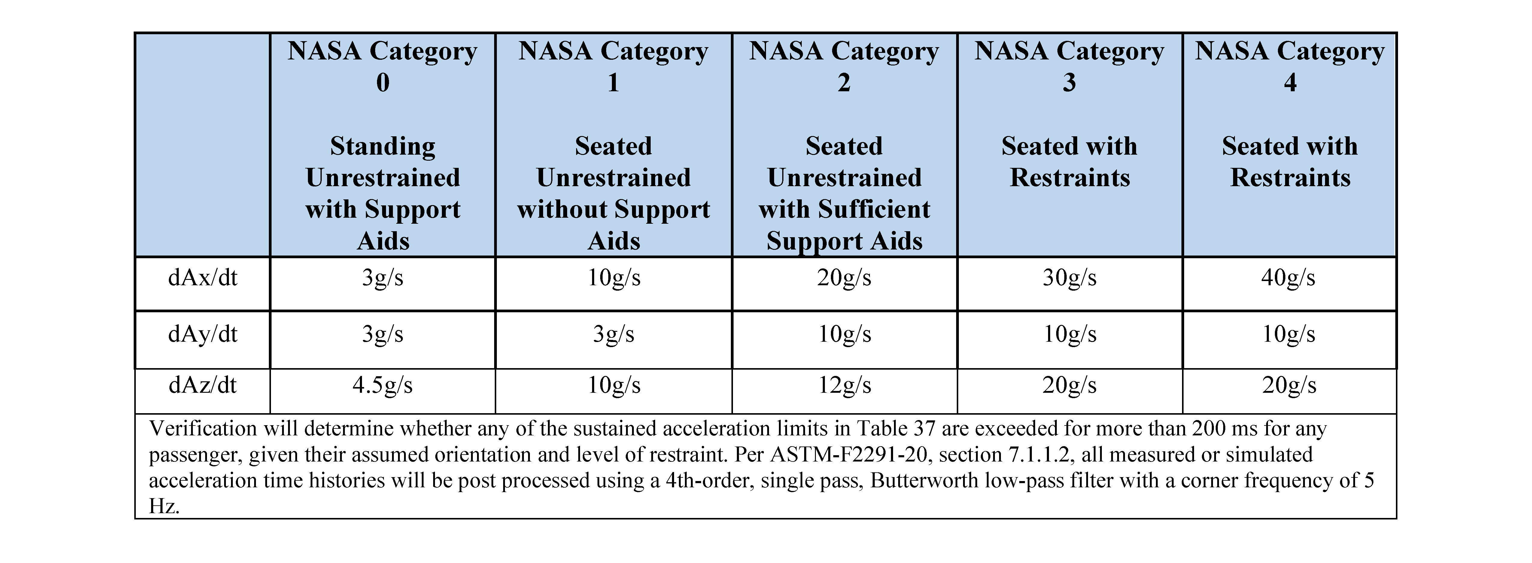
12.2.4 Emergency Egress Acceleration Limits
[V2 12046] For ground emergency egress systems (EES), the system shall limit the magnitude and direction of crew exposure to accelerations according to Table 12.1-1—EES Acceleration Limits – Sustained, and Table 12.1-2—EES Acceleration Limits – Jerk.
[Rationale: Emergency egress systems must provide and maintain a level of system safety sufficient to permit routine use of the system in crew training operations while ensuring that safety measures do not adversely affect the performance of the system during its intended use in emergency scenarios. Human tolerance levels and stability under acceleration vary broadly depending on the axes of acceleration, restraint type, duration, and condition of the subjects. The limits in this requirement represent safe levels of translational acceleration and start and stop changes in acceleration or jerk for the human. Exposure to acceleration above these limits could cause injury.
* This requirement may be revised based on tailoring of ASTM F2291-20, Standard Practice for Design of Amusement Rides and Devices, to be more specific to human spaceflight system parameters.]
Table 12.2-1—EES Acceleration Limits – Sustained
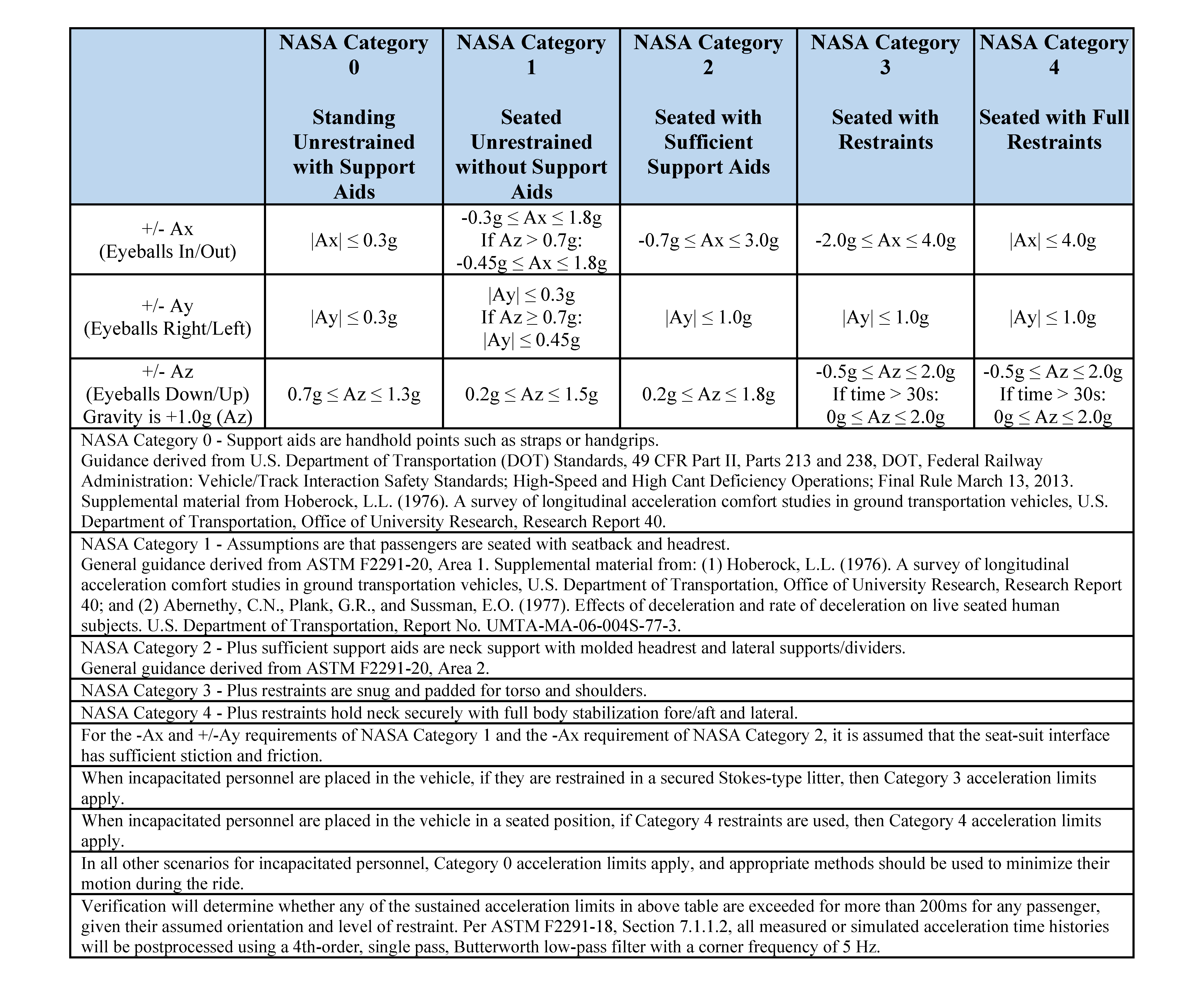
Table 12.2-2—EES Acceleration Limits – Jerk