


![Request for Information – Potential [Placeholder for Prize]](https://assets.science.nasa.gov/dynamicimage/assets/science/missions/a-step/FFR_Earth_Background_20251120%20.png?w=1024)


In situ Carbon Evolution Experiments (ICEE)
Summary
Developed through NASA Ames APEx (Ames Project Excellence) program, the ICEE (In Situ Carbon Evolution Experiments) Facility’s initial goals were to understand the origins of Solar System organics and the implications for the origins of life. However, after the facility was completed, the applicability of ICEE to virtually every area of Planetary Science research became readily apparent. As more researchers learned of ICEE’s capabilities so did the number of requests inquiring “if it was possible to do such research with ICEE?” and “How to go about using ICEE for other research activities?” Based on the growing number of requests, it was determined that ICEE should be part of the Planetary Science Enabling Facilities (PSEF) Program as a means to increase access to this facility.
The ICEE facility is a state-of-the-art planetary science research facility consisting of three separate stations: a Raman Microscope, an Ultra High Vacuum (UHV) chamber, and a Fourier transform Infrared and Raman Experiments (i.e., FIRE) station. The ICEE Facility is a NASA unique resource capable of replicating the wide range of extraterrestrial environments needed for planetary science research. The Raman microscope is equipped with an auto microscope stage and 785, 532 and 405 nm excitation lasers permitting analysis of biological and thin-film samples external to the UHV chamber fiber probe coupling. The Raman microscope has 5x, 20x, 50x and 100x objective lenses and is capable of spectroscopically mapping samples in 3D. The ICEE UHV chamber is capable of achieving vacuum down to the 10−9 torr range and sample temperatures from 15 to 300K. A gas and solid sample deposition port permits the deposition of mixed materials onto the sample window. The UHV chamber contains three analytical instruments permitting in-situ sample analysis via gas phase mass spectrometry and solid phase FTIR and Raman spectroscopy. There are three radiation sources attached to the UHV chamber: a high-energy electron gun, a soft X-ray light source (10 watts) and a flowing H2 discharge lamp. Samples within the chamber can be positioned to face one or a combination of radiation sources. The FIRE station consists of an FTIR equipped with a FT-Raman module, which utilizes a 1064 nm excitation laser wavelength. The FT-Raman module has 2D and limited 3D spectral mapping capabilities, permitting the collection of Raman spectra on solid, liquid, and gas samples. A Harrick Scientific Praying Mantis Diffuse Reflectance Infrared Fourier Transform Spectroscopy (DRIFTS) accessory is equipped with a Praying Mantis Low Temperature Reaction Chamber (-150 oC to 600 oC; high vacuum to 1 ktorr); this is used to investigate surface changes of dusts and grains, such as heterogenous catalysis, gas-solid interactions, photochemical reactions and oxidation mechanisms.
Technical Capabilities of the ICEE Facility
The ICEE Facility consists of three separate stations; Raman Microscope, an Ultra High Vacuum (UHV) chamber or ICEE UHV chamber and a Fourier transform Infrared and Raman Experiments (i.e., FIRE) station. The ICEE Facility was designed to replicate the wide range of extraterrestrial environments needed for planetary science research.
Raman Microscopic Capabilities
The Raman microscope has been detailed in several publications [1, 2]. It is a JASCO NRS 5500-532QRI instrument running the proprietary Spectra Manager II software. The instrument consists of a Czerny-Turner monochromator and a Newton EMCCD-DU970DP UV CCD (Charged Couple Device) detector and is capable of automatically switching between spectroscopic gratings of 1800 g/mm (grooves per millimeter), 600 g/mm, and 300 g/mm and apertures with diameters of 4000, 40, and 20 µm. This configuration provides a wide range of spectral and physical sampling resolutions. Fluorescence can be an issue in Raman spectroscopy, especially when analyzing organic compounds. To help overcome this issue, the Raman microscope is equipped with three excitation laser wavelengths at 785 nm (100 mW), 532 (50 mW) and 405 nm (30 mW). This selection of excitation laser wavelengths spans from the near UV to Near IR without the need for specialized optics. To prevent sample laser burning the instrument has ten attenuation filters (100, 50, 25, 10, 5, 1, 0.1, 0.01, 0.001, and 0.0001 percent) to reduce the laser power impinging on the sample. For instance, use of the 100 mW, 785 nm laser with a 50 percent attenuation filter produces a laser intensity of 50 mW. Wavelength calibration can be accomplished via a standard material, such as the 520.5 cm−1 peak of a silicon chip, or the use of the lines from an internal neon lamp.
The microscope contains an objective carousel equipped with 100x (NA-numerical aperture = 0.90), 20x (NA = 0.45), and 5x (NA = 0.15) lenses along with a 50x (NA = 0.50) long working distance objective. Video imaging is achieved via a 3 megapixel CMOS (Complementary Metal-Oxide Semiconductor) camera. The laser spot and sample measurement

points are viewable, ensuring the measurement is from the correct sample location. Prior to measurements, the laser spot is optically aligned with the optical axis of the objective lens, ensuring the laser spot aligns with the center of the aperture of the con-focal microscope system.
The microscope is capable of collecting spectra in 0.1 µm physical steps, with a spot size between 1 and 5 µm depending on the objective lens being utilized. The actual area of Raman spectral collection is dependent on the aperture and slit width settings. The automated sample stage has a travel distance of 100 mm in the X direction, and a 70 mm travel distance in the Y direction with a minimum step side of 0.04 µm. The Z axis is capable of a 30 mm travel distance with a minimum step size of 0.1 µm. Thus the microscope is capable of collecting spectra of a single point, a linear series of points (variable X or Y, constant Y or X and Z), a lattice (variable X and Y, constant Z) or even in 3D (variable X, Y, and Z).
The Raman station’s 3D mapping capabilities are demonstrated in Figures 1 and 2 which show the images of a living (green) and dead (blue) bacterial colony within an analog salt sample. In the dead colony (Figure 2), one can see a series of sharp, intense bands (1533, 1455, 1346, 1147, 685, and 597 cm−1) marked by * as well as a series of weaker, broader features (3064, 2989, 2877, 1600, 1204, and 844 cm−1), marked by *. Plotting the cyan * bands, possibly a porphyrin structure[3, 4], in 3D reveals the ellipsoidal structure of the bacterial colony, while plotting the red *, which seems to be a mixture of aromatic (3064 and 1600 cm−1) and aliphatic (2989 and 2877 cm−1) bands, display a different distribution, more on the “front and back” areas of the colony. Similarly, plotting out the cyan * features of the living colony produces the characteristic ellipsoidal shape and, as shown in Figure 2, one can view cross-sections of a vibrational modes band intensity versus depth. Interestingly, the * bands of the dead colony correspond to a porphyrin type structure while the cyan * bands (1521, 1153 and 998 cm−1 of the living colony correspond to the ν(C=C), ν(C−C), and δ(C=CH), respectively, of carotenoid vibrations, Figure 1[5, 6].
An accessory to the Raman microscope is the Linkam THMS600 Thermal stage. The thermal stage fits inside the Raman microscope and can be utilized for temperature dependent studies between -195 oC and 600 oC. The stage has a heating rate of 150 0C/min and a cooling rate of 100 0C/min. In addition to the temperature control, the stage can serve to control the atmosphere around the sample, protecting air sensitive materials. Atmospheric control is achieved via quick release gas values which serve to connect the sample holder to purge gases. The working distance required for the THMS600 stage is 4.8 mm, limiting the use of the stage to the 50x and 5x objective lenses.
ICEE Ultra-High Vacuum (UHV) Chamber Station
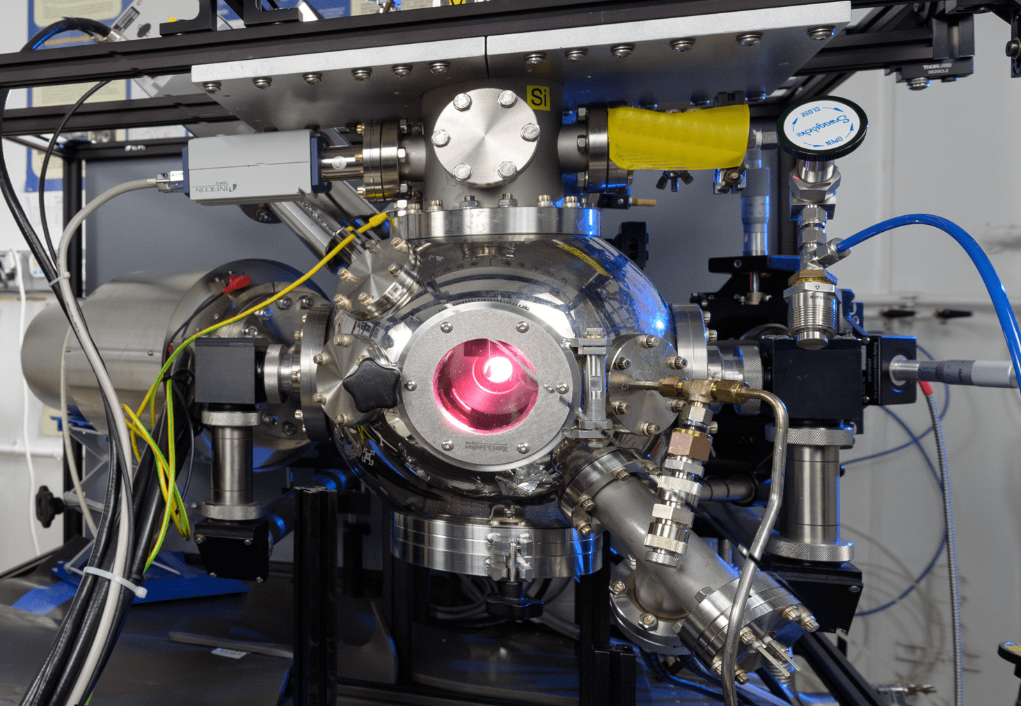
The heart of the ICEE Ultra-High Vacuum Chamber (UHV) is a 6 inch Kimball Physics Spherical Square Chamber which has been customized to accommodate ConFlat (CF) fittings from 2.75 inches to 6 inches. An overview of the chamber is provided in Figure 3 and Table 1. The chamber is capable of vacuum into the low ∼10−8 to ∼10−9 torr range utilizing an Edwards nEXT300D hybrid bearing compound turbo-molecular pump combined with a nXDS10i dry scroll pump. A 6 inch quick access port is mounted to the bottom of the sphere, providing quick access to the inside
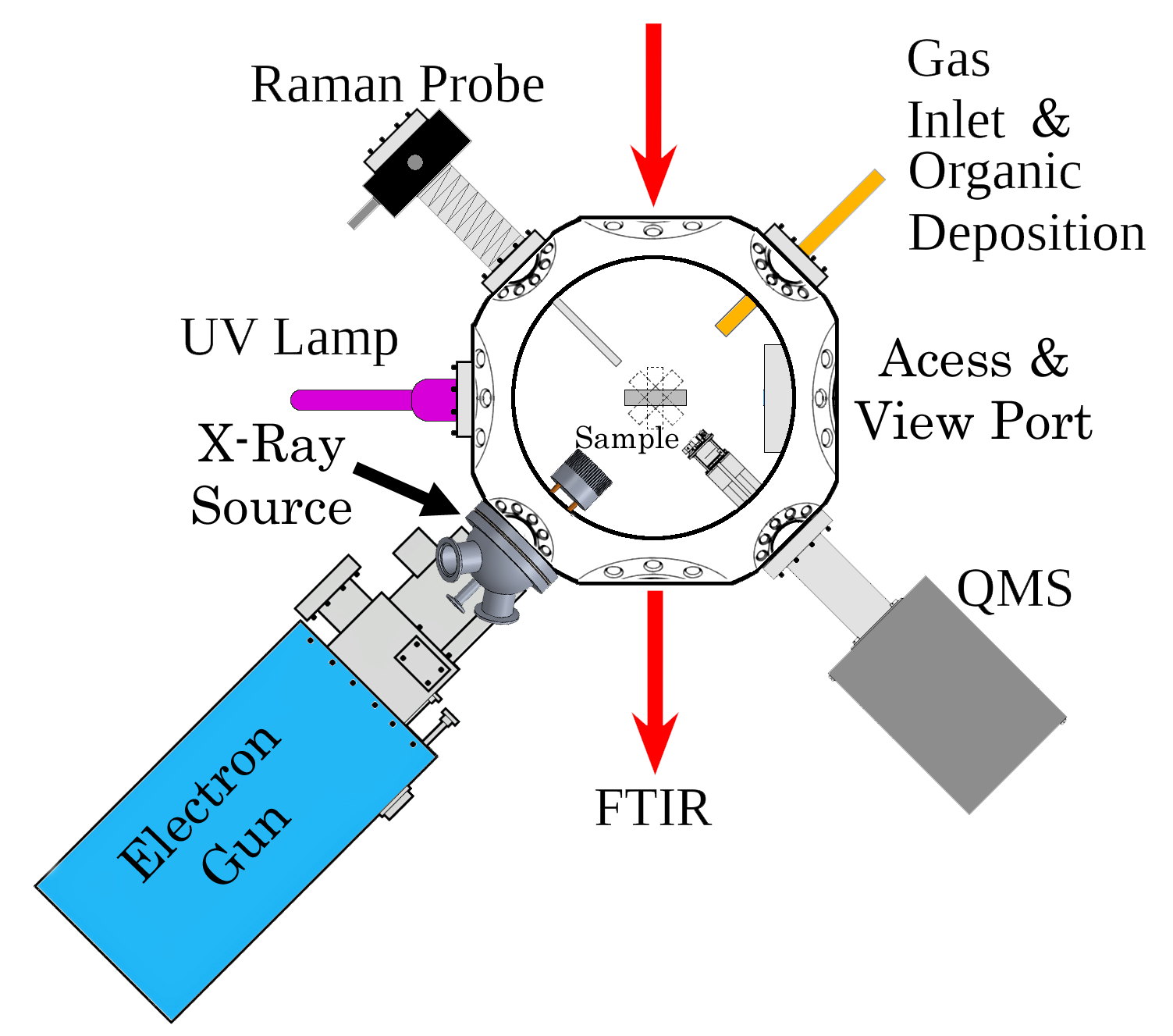
chamber, permitting chamber clean experimental setup. This image also shows the deposition port, sample mounting port and ports for extra instruments and/or radiation sources. Additionally, a 4 inch view and access port mounted on the side of the chamber provides both visual and physical access to the chamber. Mounted to/in the UHV Chamber are a sample window, deposition port, mass spectrometer, Raman probe, infrared transparent diamond windows, a Lyman alpha UV lamp, X-ray source, and high energy electron gun. Each of these components are described below.
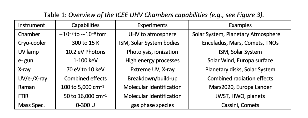
Overview of the ICEE Chamber Capabilities
Sample Window/Holder
The sample window/holder is located in the focal point of the chamber. It is mounted to the tip of a helium cryo-cooler system and capable of temperatures ranging from room temperature down to 15K. The sample holder can be rotated to face the attached deposition port, radiation sources, and in situ measurement instruments inside the chamber. Sample holders screw on to the tip of the cryo-cooler and are typically made of a stainless steel coated, high thermal conducting material, such as copper. Many types of sample holders are available (for examples see www.arscryo.com) to accommodate electrical connections and characterization, liquid samples, computer chips, and both rectangular and circular windows. The ICEE facility currently has seven sample holders capable of holding 25 mm diameter windows. Other sample holders can be provided or acquired depending on the customer’s need.
The sample window can be made from a wide variety of materials. However, if infrared (IR) transmission measurements are desired, the window needs to be made of an infrared transparent material, such as cesium iodide (CsI) or potassium bromide (KBr). ICEE personnel can assist customers in the selection of the appropriate window material, matching thermal and wavelength transmission range requirements. Samples can be deposited onto the sample window in situ through the deposition port or deposited on a window or holder and then installed in the chamber. We have the capabilities to deposit solid, liquid and gaseous sample.
Deposition Port
The sample deposition port is a quarter inch stainless steel tube which extends into the UHV chamber. The external portion of the tube has a Swagelok compression fitting which is able to accept a test tube sized receptacle. The compression fitting is typically utilized for holding a sample of refractory material, which can then be resistively heated to deposit solid material onto the UHV chamber’s sample window. Both the interior and exterior tubing can be heated to prevent condensation of the refractory material prior to deposition on sample window. The deposition tubing is also attached to a gas line through which various gases (e.g., argon, H2O) can be deposited onto the sample window.
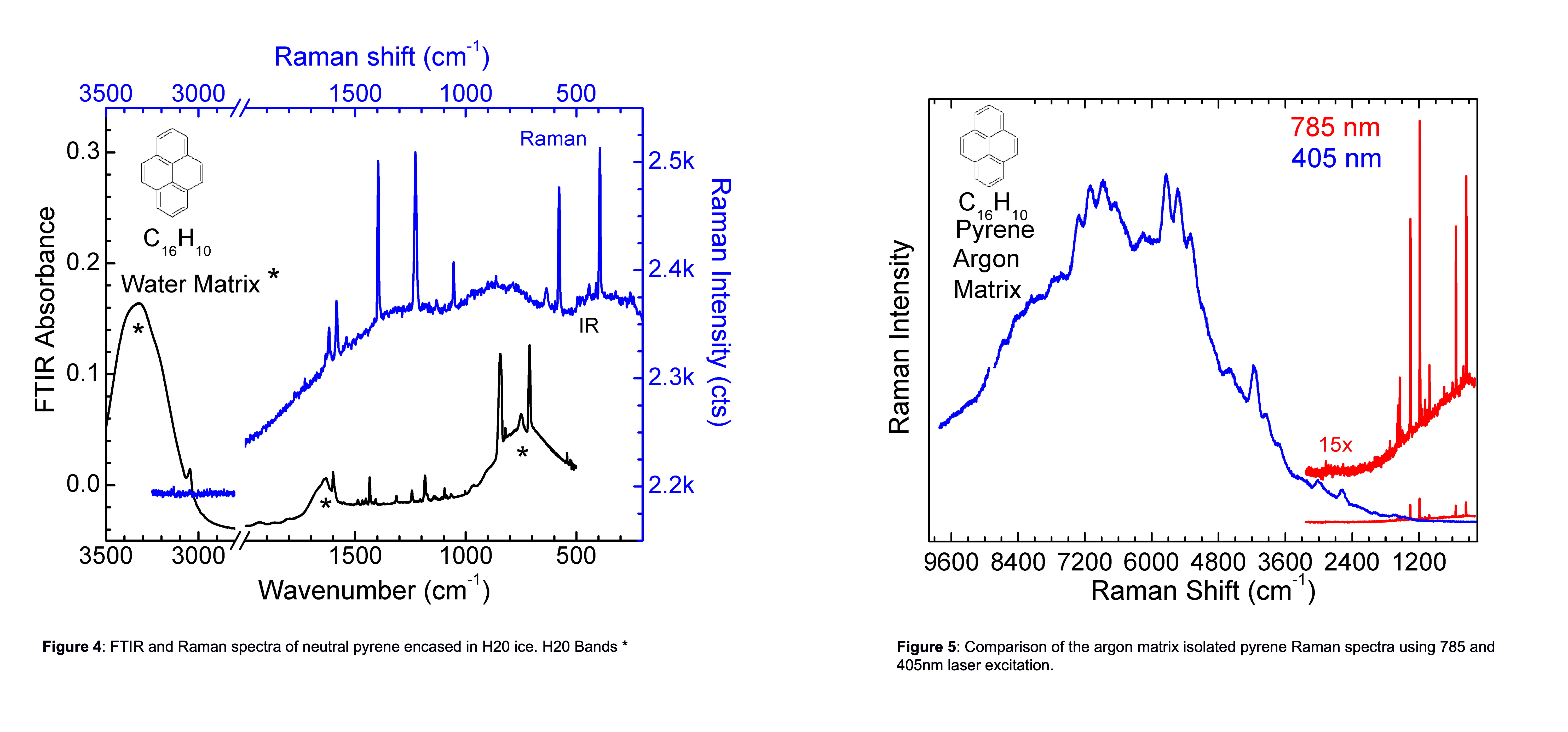
This setup permits deposition of refractory materials within various ice matrices, such as H20. For example, Figure 4 shows FTIR and Raman spectrum of polycyclic aromatic hydrocarbon (PAH) pyrene deposited within an ice matrix. Once deposited onto the window\, the sample can be turned for in situ analysis or for irradiation using the sources described below.
Mass Spectrometer
Mass spectra of gas phase species can be measured with either a Hidden HAL 3F 301 RC or Stanford Research Systems (SRS) 200 RGA (residual gas analyzer). The Hidden HAL 3F 301 RC triple filter Mass spectrometer. The triple filter provides for enhanced sensitivity for high mass transmission and increased abundance sensitivity. It also provides for enhancement of long-term stability. The mass spectrometer has a mass range of 0 to 300 u, with a resolution of 0.5 u. The mass spectrometer has both a Faraday cup and a single channel electron multiplier detector. It has an operating pressure up to 10−6 torr. The SRS 200 RGA has a mass range of 0 to 200 u, with a resolution better than 0.5 u at 10% peak height. It has a minimum detectable partial pressure of 5×10-11 Torr, when using the Faraday cup.
Raman Spectrometer
Imaging and Raman spectra of samples inside the chamber can be obtained using a WITEC alpha300R Confocal Raman Microscope. Spectra and images can be obtained using either a 20X or 50X super long working distance objective lens. A 532 nm excitation laser (30 mW) provides Raman excitation. The Raman system has an internal wavelength calibration standard.
If needed, the chamber can be connected to the Raman Microscope station by one of two available fiber optic cables. Each cable is composed of a 50 µm excitation and return fiber. One cable is equipped with a 405 nm cutoff filter and one is equipped with a 785 nm cutoff filter for use with the respective excitation lasers. The 405 and 785 nm excitation lasers bracket each side of visible spectrum, providing the optimum chance of avoiding sample fluorescence without the use of specialized optics. In this instance, wavelength calibration is achieved via a calcite (CaCO3) crystal and/or a silicon wafer, mounted onto a sample holder. An XYZ stage permits focusing on either the calibration standard or the sample surface. The wavelength range and resolution of the Raman spectrum are dependent on numerous parameters, including excitation laser, slit widths and spectroscopic gratings selected. This is demonstrated in Figure 5 which demonstrates using the 785 nm excitation laser measures out to ∼3250 cm−1, although detector sensitivity drops significantly around 2700 cm−1. However, the 405 nm laser allows one to probe beyond a Raman shift of 15,000 cm−1. As shown in Figure 5 this ability can provide information on a sample’s fluorescence spectrum as well as overtone and combination bands.
Infrared Spectroscopy and Transparent Diamond Windows
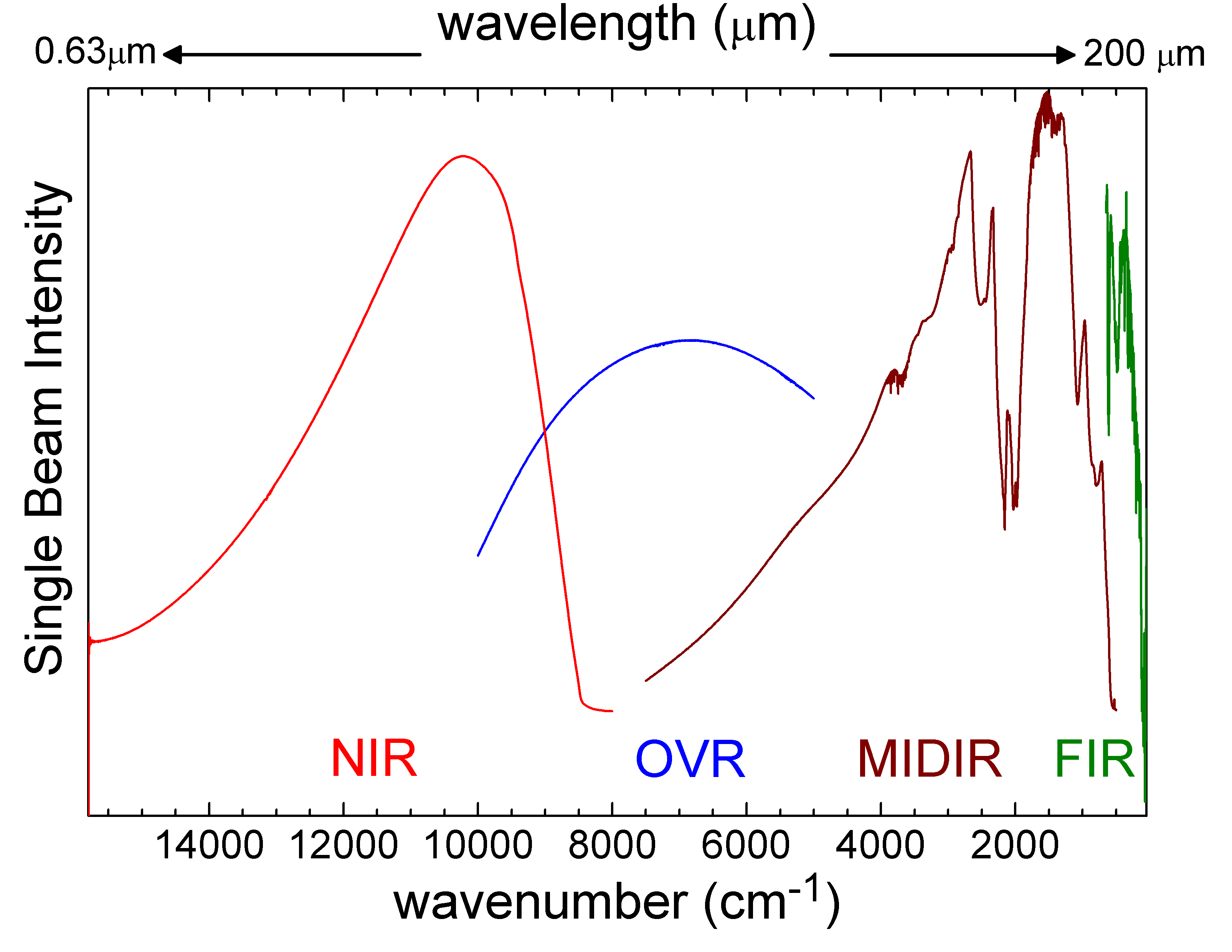
As shown in Figure 4, infrared (IR) transmission spectra of a sample can be taken once it is deposited on an infrared transparent substrate. The IR spectra are collected by passing the infrared beam through two, 27 mm diameter, diamond windows on opposite sides of the chamber. The windows vary in thickness from 200 to 400 µm, which helps reduce fringing caused by internal reflections. The diamond windows have a transmission range from 0.2 to 200 µ (50,000 to 50 cm-1), permitting a wide range of optical measurements (see Figure 6). The IR spectrometer is a Nicolet iS50 Fourier Transform Infrared spectrometer equipped with gold optics.
The instrument has three detectors, an MCT-A (11,700 to 600 cm−1, 0.85 to 16.7 µ), a silicon (27,000 to 8,600 cm−1, 0.37 to 1.2 µ), and a DLaTGS-Polyethylene (700 to 50 cm−1, 14.3 to 200 µ). An automatic beam splitter changer permits changing between a solid substrate Far-IR beam splitter (700-50 cm−1, 14.3 to 200 µ) to a Quartz beam splitter (27,000 to 2,800 cm−1, 0.37 to 3.6 µ), and an extended range KBr beam splitter (11,000 to 375 cm−1, 0.9 to 27 µ). The FTIR is connected to the diamond windows, and the ICEE UHV chamber, via axiom analytical light pipes. Taken together the FTIR setup provides IR data from nearly 16,000 down to 250 cm−1 when using a CsI sample window, see Figure 6.
Lyman α UV lamp
As in many laboratories, UV photolysis in the ICEE UHV chamber is conducted using Hydrogen’s Lyman α photons (121.6 nm, 10.2 eV), as these play a significant role in processing of organic material in the Interstellar medium (ISM) as well as inside the Solar System [7–10]. However, as pointed out in Cook et al. [11], there can be significant variations in spectral output based on lamp design and operating parameters such as H2 gas concentration, gas pressure, and microwave power.
The ICEE chamber utilizes a Resonance LTD Hydrogen VUV 121 nm light source. The Resonance lamp is a more compact system and is not sensitive to external parameters (i.e., H2 gas pressure, microwave generator power settings). Furthermore, the Resonance lamp eliminates a safety issue concerning the storage of Hydrogen gas cylinders, which are necessary for the H2 flowing discharge lamps. The lamp produces a 121.6 nm photon flux rate of 1 x 10¹⁴ photons sec-1 str-1.
X-ray Source
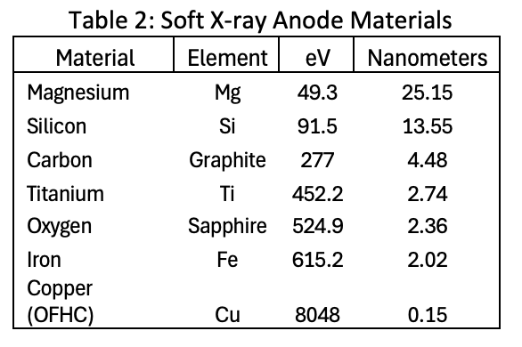
A 10-watt McPherson soft X-ray light source serves as the x-ray irradiation source in the ICEE UHV chamber. It has an operating pressure up to 10−6 torr and line emissions from less than 1 nm to 25 nm. Bright line flux is approximately 1011 photons sec−1 steradian−1. The X-ray energy is determined by the exchangeable anode material. The Table 2 provides a list of the currently available anode materials and their X-ray energy. Additional anode materials (0.049 to 9.71 keV) can be acquired as needed.
High Energy Electron Gun
Electron irradiation is provided by a STAIB Instruments EHF-100-10 Electron Flood source (electron gun) mounted to the chamber (see Figure 3). The electron gun can provide electrons in the energy range of 1 to 100 keV, with currents from 1 to 100 µA. Beam homogeneity is provided through beam wobbling, versus beam rastering, over the sample area. The system has a standby feature, permitting a pausing of the electron beam for collection of Raman and FTIR spectra. The electron gun setup provides for full coverage of the 25 mm diameter sample area at the center of the UHV chamber. It can be operated at pressures up to 10−6 torr. A Faraday cup providing information on beam homogeneity and electron flux at specific currents and energies.
This permits us to characterize the beam and measure the real time electron flux. For example, vendor specifications indicate an energy of 25 keV and an emission current of 30 µA provide an electron flux of around 1×10¹³ e− sec−1cm−1.
Accessories for the ICEE UHV Chamber
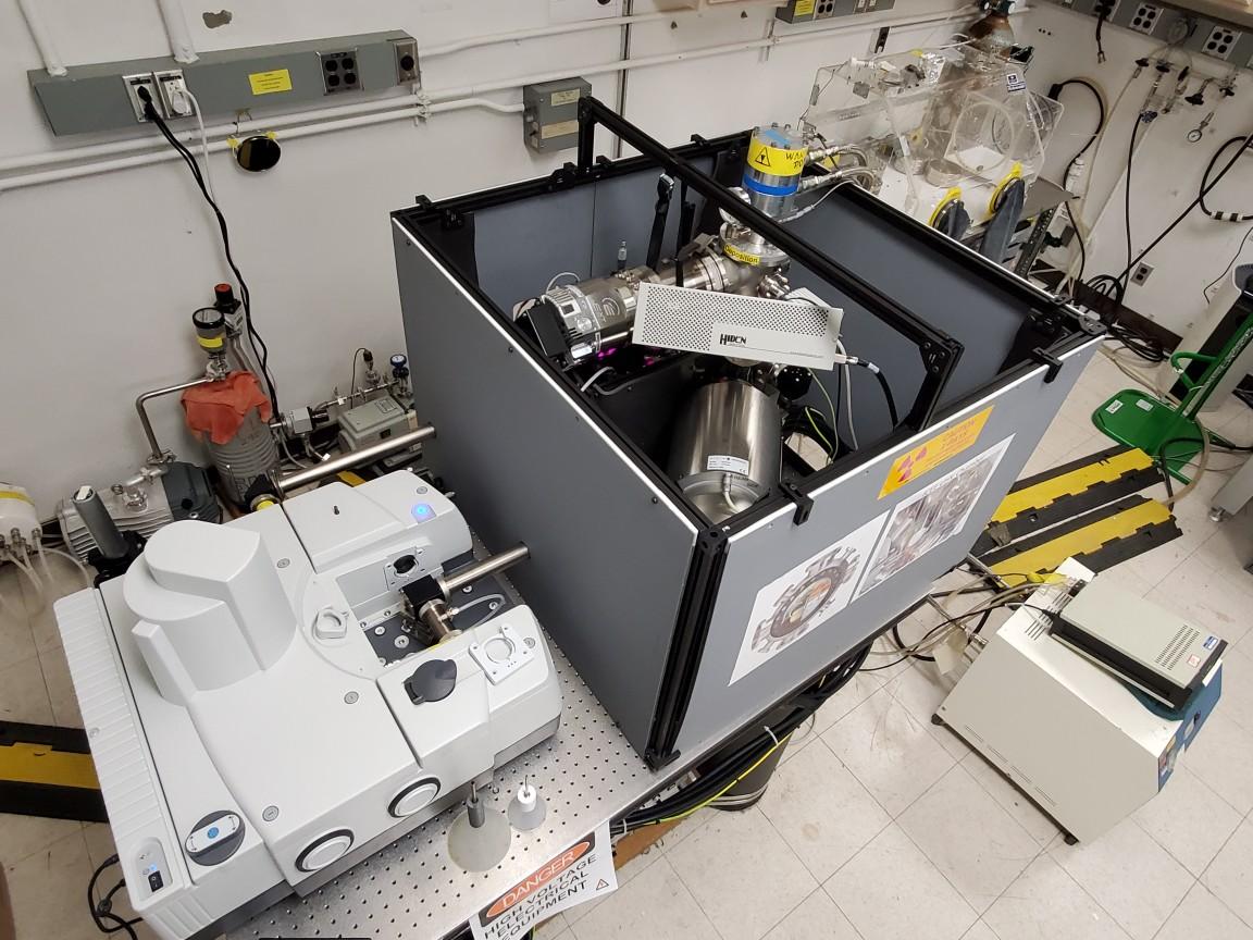
Given the potential production of harmful X-rays within the ICEE UHV chamber, the chamber has both 3.2 mm lead equivalent primary and 3.2 mm lead equivalent secondary shielding (XrayCurtains.com). This is shown in Figure 7, where the axiom analytical light pipes can be seen extending from the FTIR spectrometer into the secondary shielding material. The shielding is made of lead free material mounted between plastic panels for support creating the literal black (grey) box for science experiments.
Used in conjunction with the ICEE UHV chamber, as well as the other stations in the facility, is a vacuum glove box. The glove box provides the ability to store and handle air sensitive materials, whether they are sample return materials or materials that have been irradiated under vacuum.
Fourier transform Infrared and Raman (FIRE) Station
The FIRE (Fourier transform Infrared and Raman) Station is a iS50 Nicolet FTIR instrument equipped with a LN2 cooled MCT-A Mid-IR detector and extended range KBr beamsplitter (11,000 to 375 cm−1, 0.91 to 26.7 µm). The instrument is equipped with an iS50 FT-Raman module. The FT-Raman module utilizes a 1064 nm excitation laser and fits in the FTIR’s sample compartment.
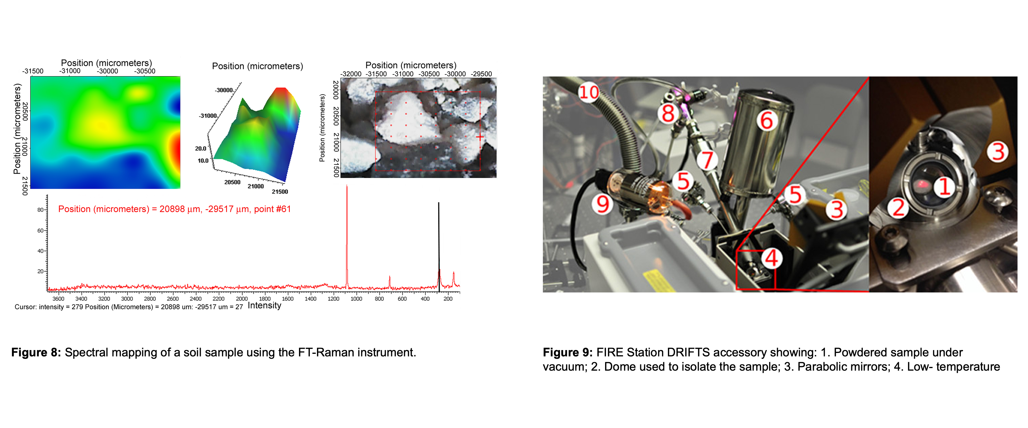
The FT-Raman comes with a variety of sample holders (i.e., microscope slide, 9 holed plate, 3 and 4 vial holder plates (i.e., vials, NMR tubes, etc.), and a 48 well plate. As shown in Figure 8, the FT-Raman is capable of 2 and 3D mapping of samples. The 1064 nm excitation laser helps combat the fluorescence issue experienced in some samples, especially organic compounds.
The FT-Raman unit can be exchanged for a Harrick Scientific Praying Mantis DRIFTS (Diffuse Reflectance Infrared Fourier Transform Spectroscopy) Accessory permitting the collection of the IR reflectance spectra of irregular surfaces, such as powders or dust grains. The DRIFTS accessory is accompanied by a modified high vacuum (1×10⁻⁶ torr) and a low temperature (-150 to 600 oC) reaction chamber made of chemically resistant 316 stainless steel.
The base unit contains three inlet/outlet ports for the introduction of gases and for evacuating the cell. The setup has been modified to permit irradiation of the sample by a flowing hydrogen discharge lamp (Lyman α, 121.6 nm, 10.2 eV).
The DRIFTS apparatus is used to study grain-surface interactions/chemistry, such as catalysis. This is demonstrated in Figure 9, where DRIFTS was used to measure the hydrogenation of the PAHs (naphthalene, anthracene, and coronene) in contact with TiO2. From these studies it was determined the TiO2 surfaces acted as a catalysis, hydrogenating the PAH without any additional energy input [15].
Planetary Science Division User Community
As previously discussed, the ICEE facility was initially developed to investigate the origins of Solar System organics and their implications for the origins of life (e.g., top-down versus bottom-up synthesis of organic molecules). Thus, the ICEE UHV Chamber is capable of replicating UV photons, high energy electrons, and soft X-rays. Given ICEE’s design goals, funding for the development of ICEE came from an Emerging Worlds (EW) proposal. Additional proposals, which include the ICEE UHV station, have been submitted to the EW program.
The ICEE UHV station has also been part of a Solar System Workings project as well as Exobiology and ICAR (Interdisciplinary Consortia for Astrobiology Research) proposals. Researchers investigating the chemistry of Proto-Planetary disks (Exoplanet research) have also inquired about how to utilize the UHV station. Planetary protection studies are also a possibility given the capabilities of the UHV station. Researchers from the Mars community have also expressed interest in using the UHV station’s controlled environment and radiation sources to mimic Martian conditions. Thus, there is significant interest withing the Planetary Science Community for using the ICEE UHV Station.
The Raman microscope was funded through NASA’s Laboratory Analysis of Returned Samples (LARS) program. Since its acquisition, we have successfully proposed and analyzed a grain from the Japanese Hayabusa2 asteroid sample return mission and we hope to analyze samples from OSIRIS-REx soon. Furthermore, a potential NPP (NASA Postdoctoral Program) candidate is proposing to utilize the Raman microscope as an analytical instrument in a multi-laboratory project aimed at understanding the origin and evolution of organics in space. Researchers have also inquired if the Raman microscope could be utilized to measure their analog field samples (Planetary Science and Technology through Analog Research). In fact, the Raman Microscope has been included in at least three PSTAR proposals since its installation.
![Figure 10: Overview of the carbon nanograin experiments which utilized the Raman microscope [2] showing Raman: microcrystals as light blue and white, nanograins on a yellow background, and COSmIC showing Pyrene gas](https://www.nasa.gov/wp-content/uploads/2023/08/images-large-sp2c00136-0010.jpeg)
This past year we received two requests to have analog samples ran on the Raman microscope. It is also being used to test design concepts for new planetary mission proposals. Likewise, researchers have expressed an interest in using the microscope for analyzing samples produced in their laboratories. An example of this is shown in Figure 10, which is the Raman spectrum of carbon nanograins made in the NASA Ames COSmIC facility from the PAH pyrene. The microscope permitted the analysis of the precursor pyrene as well as the resulting carbon nanograin material.
The Harrick Scientific Praying Mantis DRIFTS setup was initially funded through NASA’s Astrobiology program to investigate the role of grain/dust surface catalysis on the production of prebiotic molecules. Currently, an NPP candidate is interested in a cross-discipline project determining the role of dust grain surface catalysis on the degradation of refractory organic material within a proto-planetary disk and its role in the vapor phase carbon species abundance (Exoplanet research). The FT-Raman portion has been used to measure analog samples, as shown in Figure 8. As such, the FT-Raman shows great potential for PSTAR proposals. When a high degree of magnification is not needed or fluorescence is a major issue, the FT-Raman will perform functions like the Raman microscope, making it useful for the analysis of returned samples (LARS), as well as laboratory samples developed for SSW or EW.
Facility Management Plan
The ICEE Facility, located in the Planetary Systems Branch, NASA Ames Space Sciences and Astrobiology Division, Moffett Field, CA, is part of the NASA Ames Astrophysics and Astrobiology Laboratory Group. ICEE personnel include Dr. Andrew Mattioda, Dr. Katarina Yocum, Dr. Caroline Dang, Dr. Akant Vats, Lab Manager Greg Schlick, and Engineering Technician Mr. Emmett Quigley.
Access
The ICEE Facility is located on the NASA Ames Research Center campus. As such, there are two steps for facility access: access to NASA Ames Research Center and access to the ICEE Facility. Access to Ames is granted through NASA’s Visitor Badging Office. ICEE Facility users, who are U.S. citizens or Green Card holders, will need to contact ICEE’s admin two weeks prior to the start of their experimental runs to obtain a visitor pass. ICEE’s Admin will assist customers with filling out the online forms (link to new form) and ensuring the proper documentation has been submitted. Facility users who are foreign nationals will need to contact the ICEE’s admin at least two months prior to the start of their experimental runs. This is to cover the extra time required for processing foreign national visitor requests. Foreign nationals will require a NASA foreign escort during their visit to the ICEE Facility. The facility will arrange the foreign national escort. However, this may limit foreign national access at times.
Given the facilities radiation sources, it is a secure facility. Thus, customers are only allowed in the facility when an ICEE team member is present. Given the complexity of the instrumentation and equipment involved in the ICEE Facility, all proposed experiments will be ran by ICEE personnel. Personnel are available 6 a.m. to 6 p.m. for experimental runs.
This time frame also corresponds to NASA Ames Visitor Center office hours.
Access Solicitation
Access to the ICEE facility is through the ICEE Facility’s website (https://www.nasa.gov/insitu-carbon-evolution-experiments-icee/). Potential customers can apply for time by submitting the form available on the website (link to new form).
References
- AL Mattioda, L Gavilan, CL Ricketts, PK Najeeb, A Ricca, and C Boersma. The nasa raman spectroscopic database: Ramdb version 1.00. Icarus, 408:115769, 2024.
- Lisseth Gavilan, Claire L Ricketts, Salma Bejaoui, Alessandra Ricca, Christiaan Boersma, Farid Salama, and Andrew L Mattioda. Raman spectroscopic study of pyrene in cosmic dust analogues: evolution from the gas to the solid phase. ACS Earth and Space Chemistry, 6(9):2215–2225, 2022.
- Metin Aydin. Dft and raman spectroscopy of porphyrin derivatives: Tetraphenylporphine (tpp). Vibrational Spectroscopy, 68:141–152, 2013.
- Metin Aydin and Daniel L Akins. Infrared and raman spectroscopic characterization of porphyrin and its derivatives. Applications of Molecular Spectroscopy to Current Research in the Chemical and Biological Sciences; Stauffer, MT, Ed, page 141, 2016.
- Jean Claude Merlin. Resonance raman spectroscopy of carotenoids and carotenoidcontaining systems. Pure and Applied Chemistry, 57(5):785–792, 1985.
- Craig P Marshall and Alison Olcott Marshall. The potential of raman spectroscopy for the analysis of diagenetically transformed carotenoids. Philosophical Transactions of the Royal Society A: Mathematical, Physical and Engineering Sciences, 368(1922): 3137–3144, 2010.
- PA Gerakines, MH Moore, and RL Hudson. Energetic processing of laboratory ice analogs: Uv photolysis versus ion bombardment. Journal of Geophysical Research: Planets, 106(E12):33381–33385, 2001.
- Max P Bernstein, Scott A Sandford, Louis J Allamandola, J Seb Gillette, Simon J Clemett, and Richard N Zare. Uv irradiation of polycyclic aromatic hydrocarbons in ices: production of alcohols, quinones, and ethers. science, 283(5405):1135–1138, 1999.
- Amanda M Cook, Andrew L Mattioda, Antonio J Ricco, Richard C Quinn, Andreas Elsaesser, Pascale Ehrenfreund, Alessandra Ricca, Nykola C Jones, and Søren V Hoffmann. The organism/organic exposure to orbital stresses (o/oreos) satellite: radiation exposure in low-earth orbit and supporting laboratory studies of iron tetraphenylporphyrin chloride. Astrobiology, 14(2):87–101, 2014.
- Y-J Chen, K-J Chuang, GM Muñoz Caro, M Nuevo, C-C Chu, T-S Yih, W-H Ip, and CYR Wu. Vacuum ultraviolet emission spectrum measurement of a microwave-discharge hydrogen-flow lamp in several configurations: Application to photodesorption of co ice. The Astrophysical Journal, 781(1):15, 2013.
- Amanda M Cook, Andrew L Mattioda, Richard C Quinn, Antonio J Ricco, Pascale Ehrenfreund, Nathan E Bramall, Giovanni Minelli, Emmett Quigley, Ryan Walker, and Robert Walker. Sevo on the ground: design of a laboratory solar simulation in support of the o/oreos mission. The Astrophysical Journal Supplement Series, 210(2):15, 2014.
- I Alata, GA Cruz-Diaz, GM Muñoz Caro, and E Dartois. Vacuum ultraviolet photolysis of hydrogenated amorphous carbons-i. interstellar h2 and ch4 formation rates. Astronomy & Astrophysics, 569:A119, 2014.
- Florina-Elena Truica-Marasescu and Michael R Wertheimer. Vacuum ultraviolet photolysis of hydrocarbon polymers. Macromolecular Chemistry and Physics, 206(7):744–757, 2005.
- GA Cruz-Diaz, SE Erickson, EF Da Silveira, A Ricca, ALF De Barros, CAP Da Costa, RC Pereira, and AL Mattioda. Pah products and processing by different energy sources. The Astrophysical Journal, 882(1):44, 2019.
- Gustavo A Cruz-Diaz, Alessandra Ricca, and Andrew L Mattioda. Polycyclic aromatic hydrocarbons and dust particle surface interactions: Catalytic hydrogenation of polycyclic aromatic hydrocarbon molecules under vacuum conditions. ACS Earth and Space Chemistry, 4(10):1730–1742, 2020.
You can download the ICEE brochure here.