


Quick Facts
Year Built: 1939
Historic Eligibility: National Register Eligible
Important Tests: Free-Flight Testing, Static Testing, Dynamic Testing
History
In the late 1930s, after successfully advocating for designing and initiating operations of the 15-foot vertical spin tunnel, Charles H. Zimmerman conceived and successfully developed another unique wind tunnel apparatus to study the dynamic stability and control characteristics of an aircraft model in a free-flying condition.
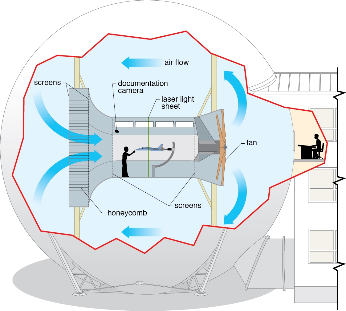
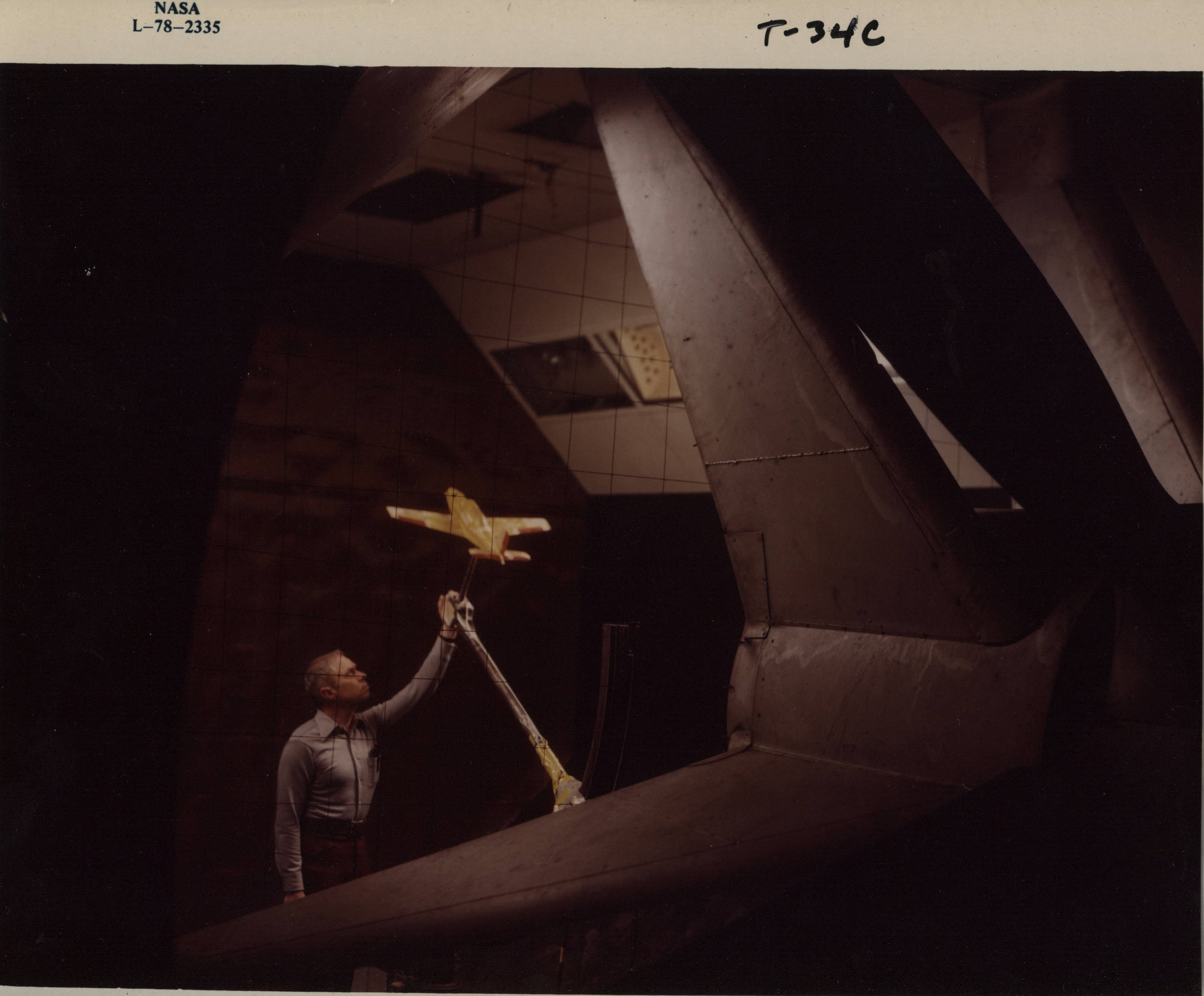
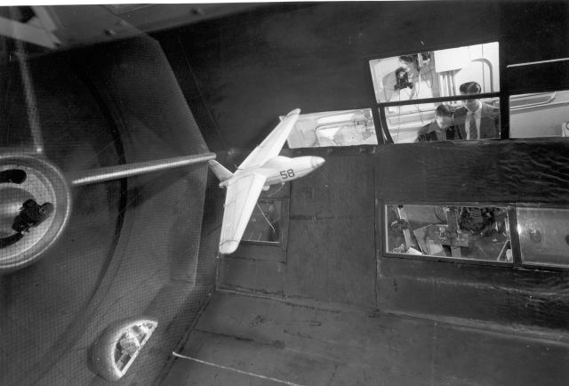
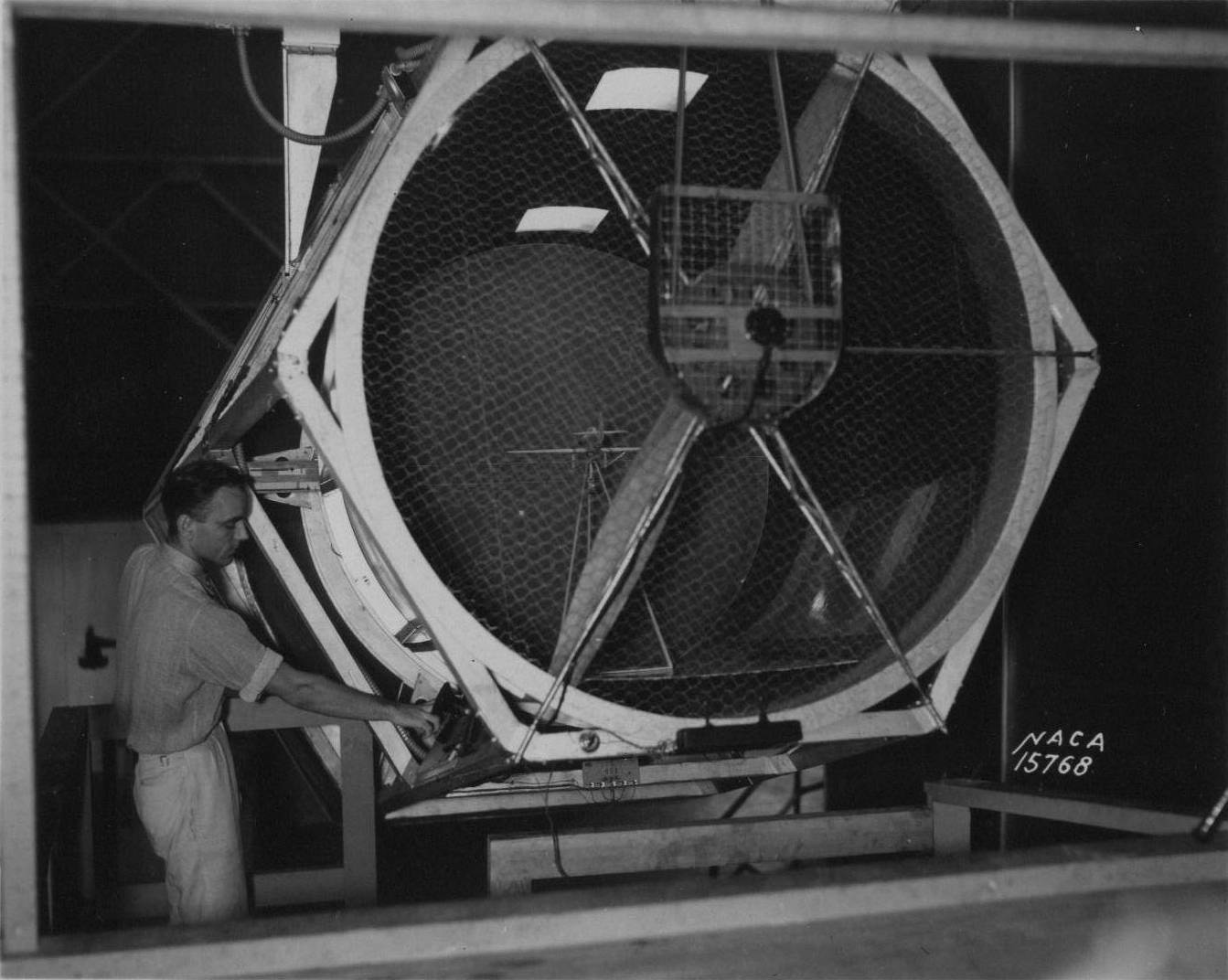
A 5-foot-diameter “proof-of-concept” wind tunnel was constructed and suspended from a yoke that permitted it to be rotated about a horizontal axis and tilted from the horizontal position to a nose-down orientation up to an angle of 25 degrees. A tunnel operator stood at the side of the test section and controlled the tilt angle of the tunnel as well as the airspeed produced by a fan located at the right rear of the test section. His main function was to adjust the airspeed and tunnel angles so that the model remained stationary in the center of the tunnel during a test. The evaluation pilot was positioned at the rear of the tunnel where he could easily see the lateral motions of the model and provide inputs to the model’s controls via fine wires that were kept slack during the flight.
In a typical free-flight test, the model was placed at the center of a takeoff platform and the elevator or model pitch control was manually adjusted to a desired setting. The tunnel angle was adjusted to the expected glide path of the unpowered model and the airspeed was slowly increased until the model rose from the platform and assumed a flying attitude. The tunnel operator and evaluation pilot coordinated their tasks to permit an assessment of the relative stability and responses of the model to control inputs.
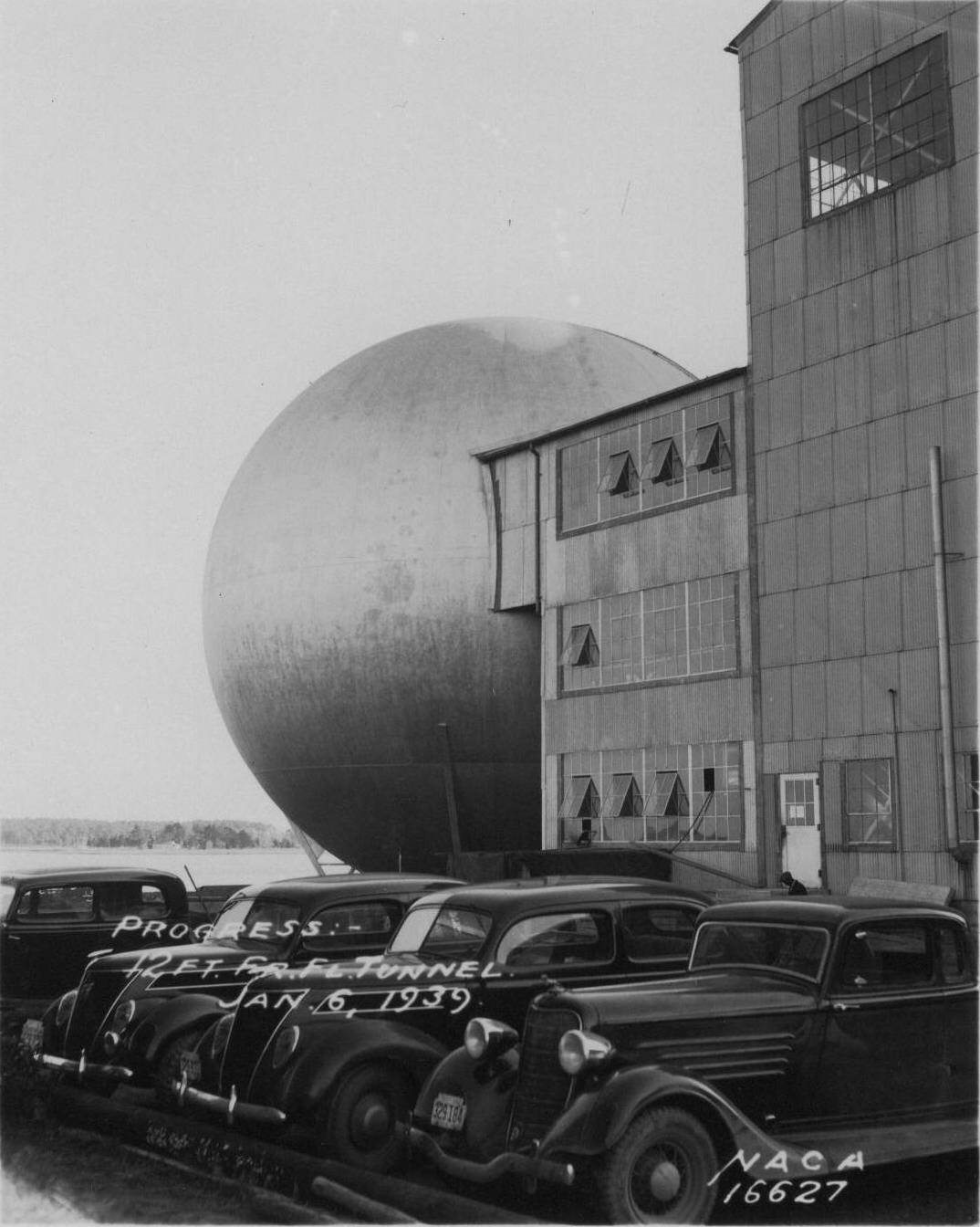
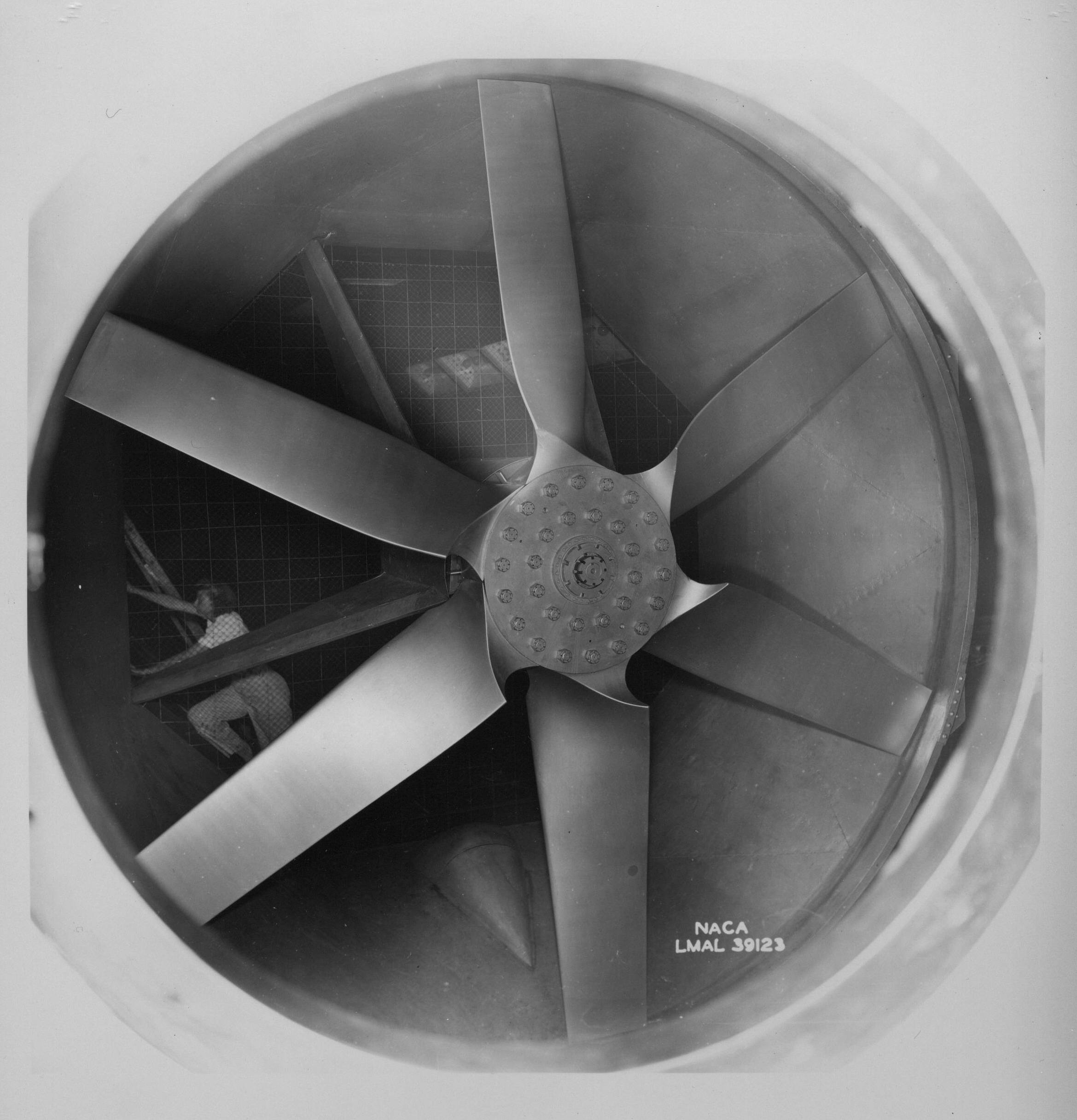
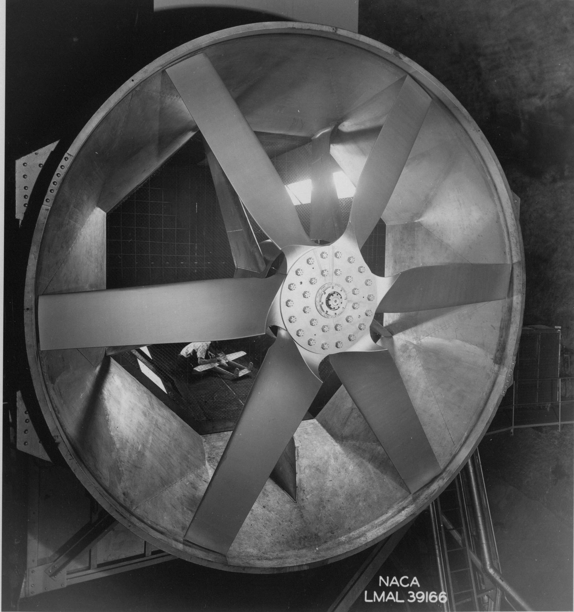
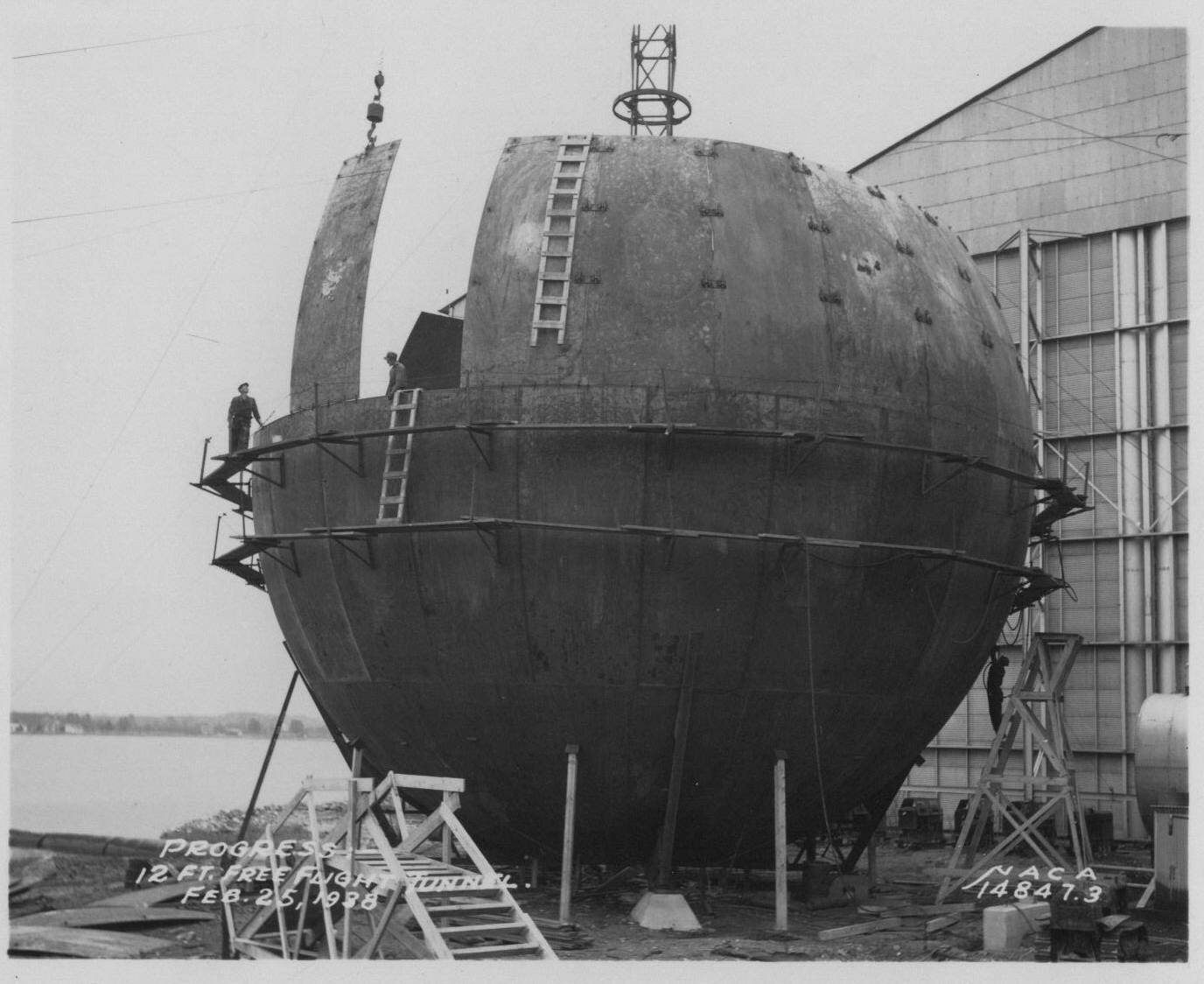
Initial testing in the 5-Foot Free-Flight Tunnel started in 1937 with very encouraging results, including the development of an automatic light-beam-control device to reduce crashes during the learning process. Zimmerman’s team quickly designed and developed a larger free-flight capability for a 12-foot tunnel with an octagonal test section in 1939.
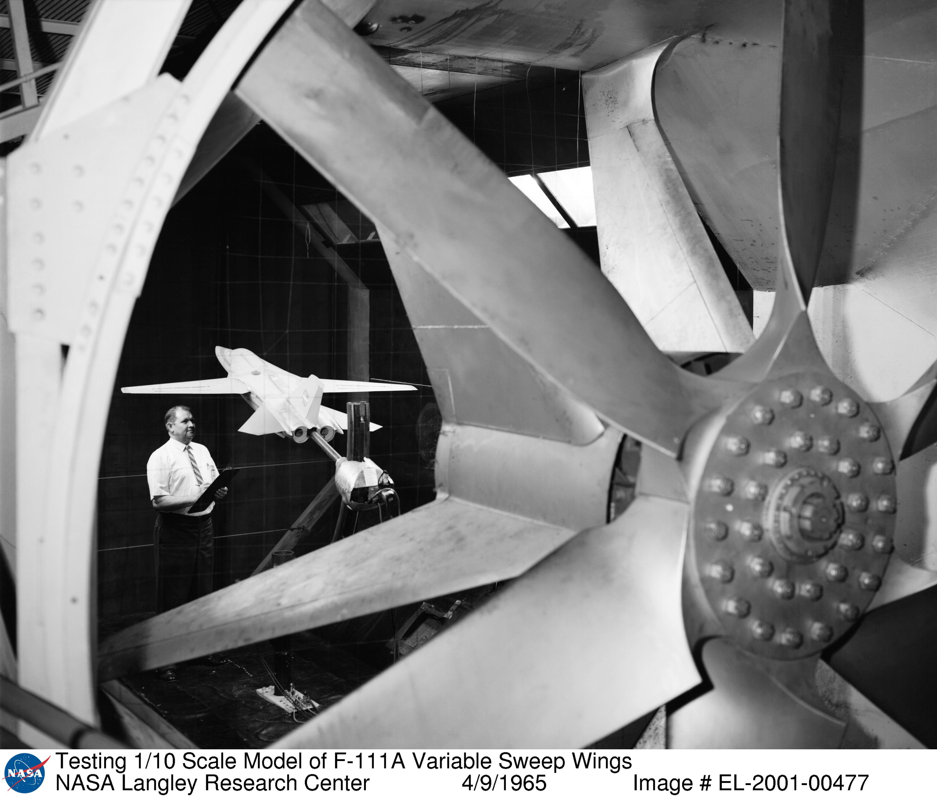
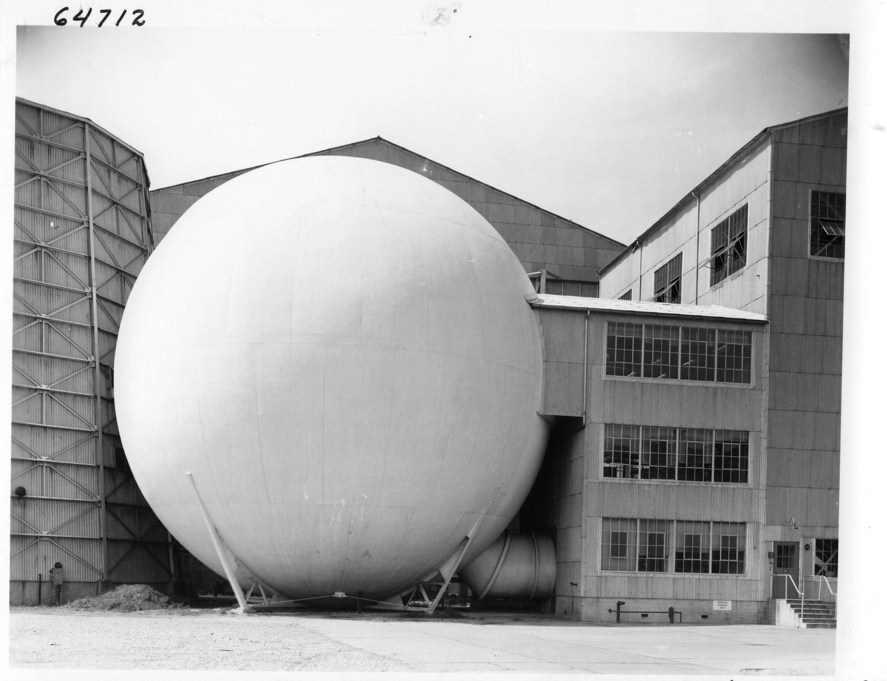
Housed in a sphere near the current spin tunnel, the Langley 12-Foot Free-Flight Tunnel (later known as the Langley 12-Foot Low-Speed Tunnel) provides all-weather test capability adjacent to an office building staffed by researchers and support crews. The closed-circuit free-flight tunnel initially operated with a tiltable (hydraulically-driven) test section in a two-operator mode similar to the earlier tunnel. For about 20 years, highly successful studies of radical aircraft configurations were conducted, during which advancements in internal strain-gauge technology permitted not only free-flight evaluations but also measurements of the aerodynamic characteristics of free-flight models during conventional wind tunnel tests.
In 1958, a slack in the post-war operational schedule of the Langley Full Scale Tunnel permitted exploratory free-flight tests to be conducted in its gigantic 30 x 60-foot test section, providing much more freedom and less risk during flight tests. In addition, the models could be much larger and sophisticated than the simple balsa models used in the free-light tunnel. For these reasons, the free-flight technique was transferred to the larger wind tunnel. When the technique was transferred, the free-flight tunnel was converted for conventional force-test studies of aerodynamics and its test section was fixed in a horizontal attitude.
The tunnel was used as an exploratory low-cost test facility for over 50 years, and was in continuous use by NASA Langley for static and dynamic force tests in later decades.
Search the NASA Technical Reports Server for additional examples of the research conducted in this facility. Examples include:
- Preliminary Stability and Control Tests in the NACA Free-flight Wind Tunnel and Correlation with Flight Tests
Related Materials
1939 Floorplan (Revised 1970)
1948 Floorplan
2013 Floorplan
Langley Memorial Aeronautical Laboratory Description of Flight-Flight Tunnel