


This article is from the 2021 NESC Technical Update.
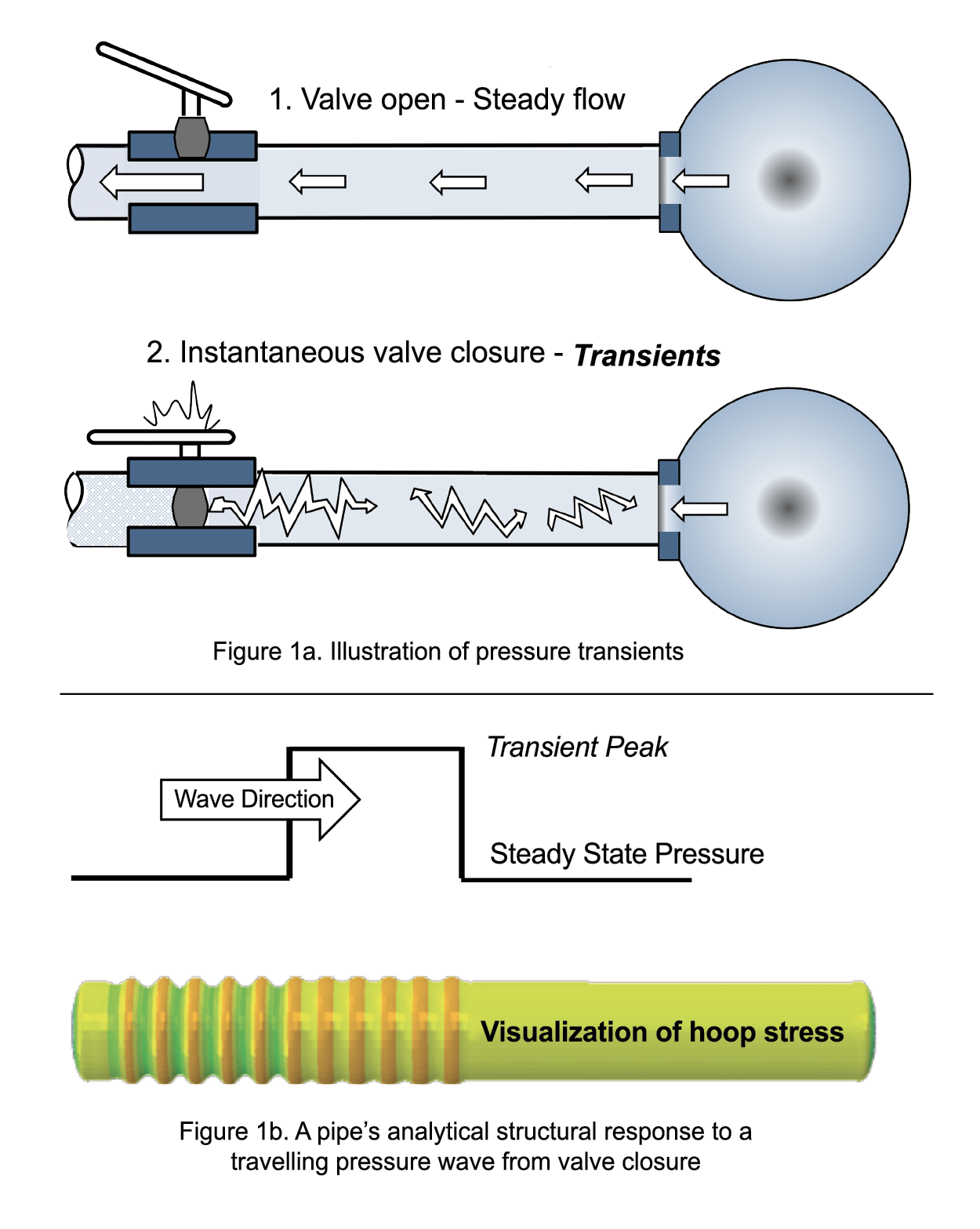
Transient pressure events are dynamic fluctuations due to disruptions within pressurized systems. Analytical and experimental evidence have shown that fast-moving pressure transients can elicit an amplified structural response above a static response. Structural failures have occurred from inadvertent overload or cyclic fatigue from pressure transients in many aerospace applications. The concept of a transient event is illustrated in Figure 1a. A pipe connecting a tank and an open valve shows steady fluid flow. As the valve is suddenly closed, a bow wave results in a dynamic pressure rise with the wave traveling back and forth between the tank and the valve. The ensuing pressure spikes, Figure 1b, can lead to pressure system component failures.
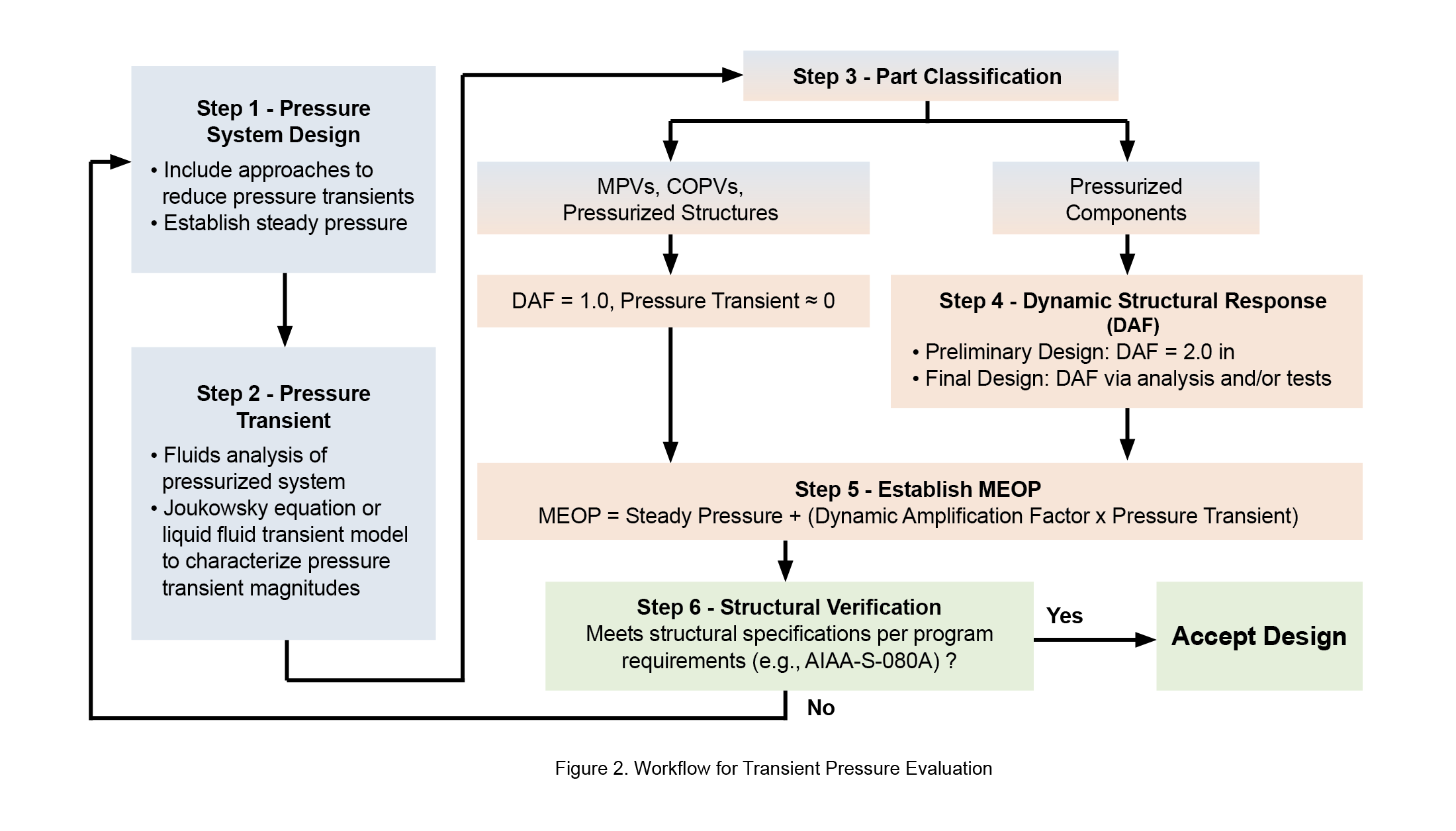
The NESC published a position paper to improve understanding of pressure transients caused by flow disturbances and document best practices with a roadmap (Figure 2), given the number of new entrants into the commercial space field where launch of crewed spacecraft is the main objective [1]. Five aspects of transients are presented: (1) fundamental physics of the contributing sources, and major influencing factors of transients in pressurized systems, (2) mitigation strategies to reduce the magnitude of pressure transients, (3) prediction or measurement of pressure transients with case studies illustrating their application, (4) prediction or measurement of dynamic response of the structure to transients along with case studies to illustrate methods to predict the amplified stress response, and (5) the structural verification process, which requires an understanding of the critical stress states within the pressurized hardware.
Characterizing transients in system design is performed via fluids analysis or test. The Joukowsky equation provides a simple and conservative means to predict transients for “instantaneous” valve closures. Another approach is to create one-dimensional fluid models consisting of a pair of coupled first-order partial differential equations involving continuity and momentum equations. A more detailed two-dimensional or three-dimensional model can be developed to capture losses and other geometric effects but requires additional effort to create and validate the model. Alternative to analytical models, transients can be characterized by performing instrumented (e.g., pressure transducers) subsystem tests that incorporate test-like-you-fly operational aspects (e.g., valve closure schedule).
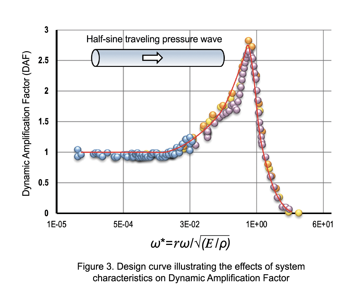
Once the magnitude of a pressure transient is determined, it is important to assess the structure’s response to these transient pressures. The structure’s dynamic response is influenced by the component’s geometry and material properties and the pressure wave velocity, amplitude, and shape. This dynamic response may result in amplification of stresses due to resonance or may not be affected at all depending upon the characteristics of the system. A ratio called dynamic amplification factor (DAF) provides a quantitative measure of the structure’s dynamic response compared to the case where the same pressure load is applied statically. The DAF can be predicted using a structural dynamic analysis. The analysis should consider wave reflections from boundaries as it can result in higher DAF. A parametric study was performed by varying the radius (r), wall thickness (t), modulus (E), and density (ρ) of a pipe subjected to a half-sine traveling pressure wave to understand the effects on DAF. Through this study, it was found that the ratio, ω*, of pressure wave frequency, ω, to the ring natural frequency of the pipe, ωn, in rad/s, ω* = ω/ωn = rω/ √E / ρ was a key parameter in the calculations of the DAF.
Figure 3 presents a case study that shows the DAF relationship with varying ω*. With an assumed structural damping of 2%, three outcomes are possible:
ω* << 1 → similar to static pressure load, DAF = 1
ω* = 1 → resonance, response is amplified, DAF ~ 3
ω* >> 1 → structure responds slower than the load, DAF ~ 0
A graphical presentation similar to that in Figure 3 can be a useful design tool for many applications. Even a fast-moving pressure wave can cause a significant dynamic structural response, and its effects cannot always be ignored. Another approach to measuring the DAF is via subsystem tests where components can be instrumented with strain gages to directly measure the structural DAF.
The NESC paper and NASA/TM-20210022275 outline approaches to include DAF in the structural verification process. For fluid storage vessels such as tanks and pressurized structures, the pressure wave entering the vessel dissipates due to their relatively large volume compared to the connecting pipe. In these cases, the DAF is set to zero while the magnitude of the pressure transient is combined with the steady-state pressure in the vessel to determine the maximum expected operating pressure (MEOP). On the other hand, the transient pressure in pressurized components such as pipes and valves can result in either a minimal structural response (DAF~0.0), a quasi-static response (0.0 < DAF < 1.0), or an amplified response (DAF ≥ 1.0) above the static response. It is recommended to establish a MEOP such that the maximum stress produced by static pressure is equivalent to the maximum stress at the same critical location produced by the combined effect of steady state pressure and the magnitude of the pressure transient. An alternative approach is to adjust system pressure test levels to meet structural verification criteria without adjusting the MEOP definition. A damage tolerance approach with lower proof and burst factors is presented, which can result in weight savings, especially when pressure transient magnitudes are significant. For more information, contact kauser.s.imtiaz@nasa.gov or vinay.k.goyal@aero.org.
References
- K. Imtiaz, V. Goyal, P. Babuska, E. Barbour, and J. Smith, “Treatment of Transient Pressure Events in Space Flight Pressurized Systems” NESC, NASA/TM-20210022275, https://ntrs.nasa.gov/citations/20210022275.