


Quick Facts
Year Built: 1934
Historic Eligibility: National Register Eligible
Important Tests: Airfoils, Shock Waves, Schlieren Photography, Computer Research Data Development
History
After the highly successful operational debut of the Langley Variable Density Tunnel (VDT) in 1922, management suggested that the considerable energy contained in the compressed air used to power the VDT be utilized in a “blowdown” mode to power a high-speed test apparatus. The first successful application was to power an 11-Inch High-Speed Tunnel in the same building as the VDT.
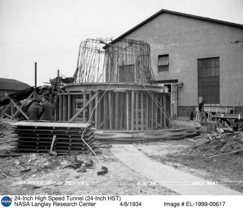
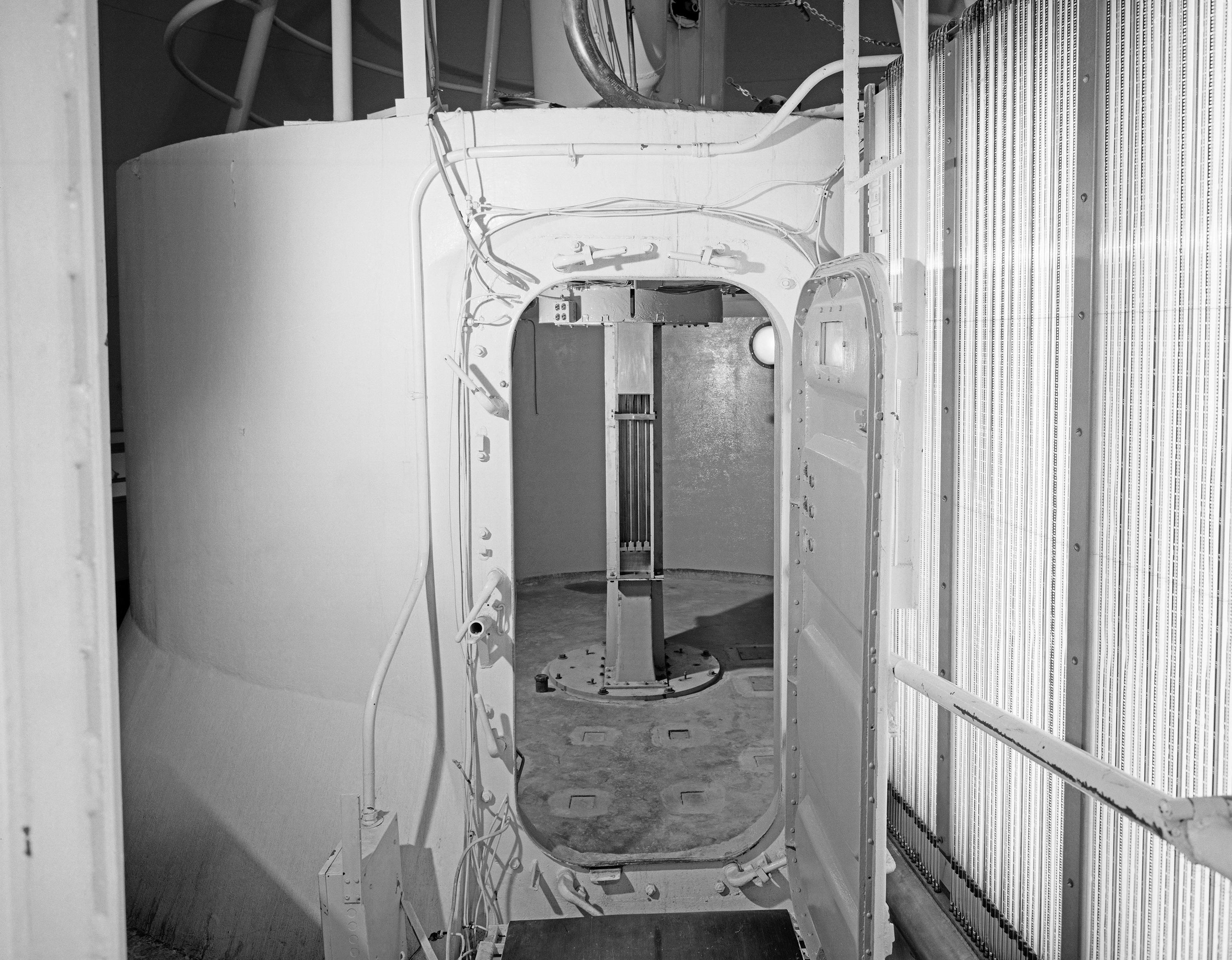
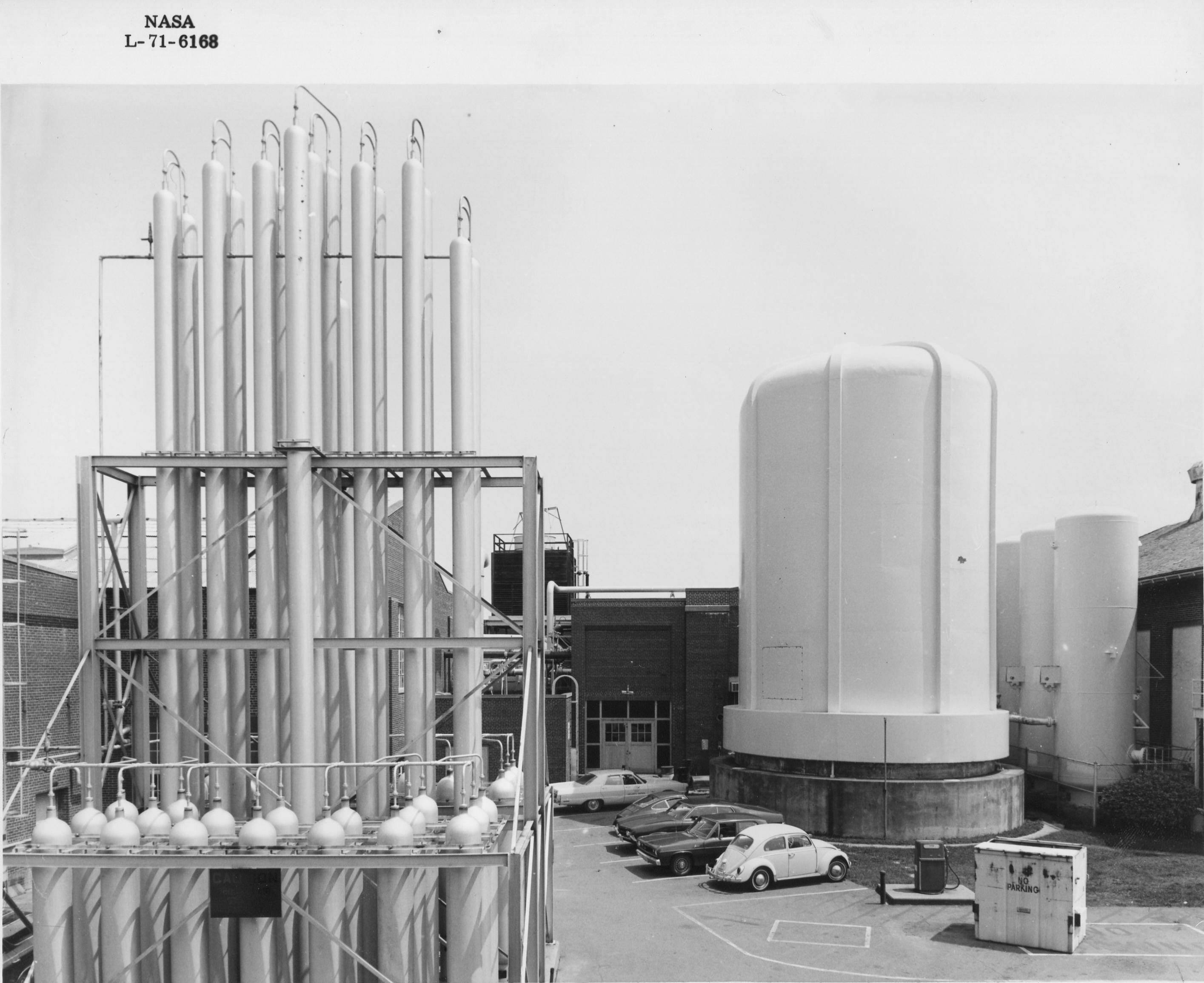
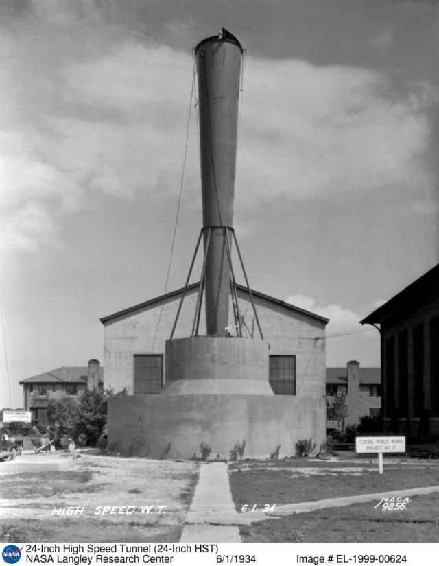
Encouraged by results from this induction-type tunnel, Langley constructed a larger 24-Inch High-Speed Tunnel, Building 585, located next to the VDT for transonic testing at twice the Reynolds numbers of the 11-Inch Tunnel. The new facility was also an induction-type tunnel and its drive system used blowdown of compressed air supplied from the VDT compressor. The induction principle injected the high-pressure blowdown air downstream of the test section, resulting in entrainment of the surrounding atmospheric air at transonic speeds through the test section.
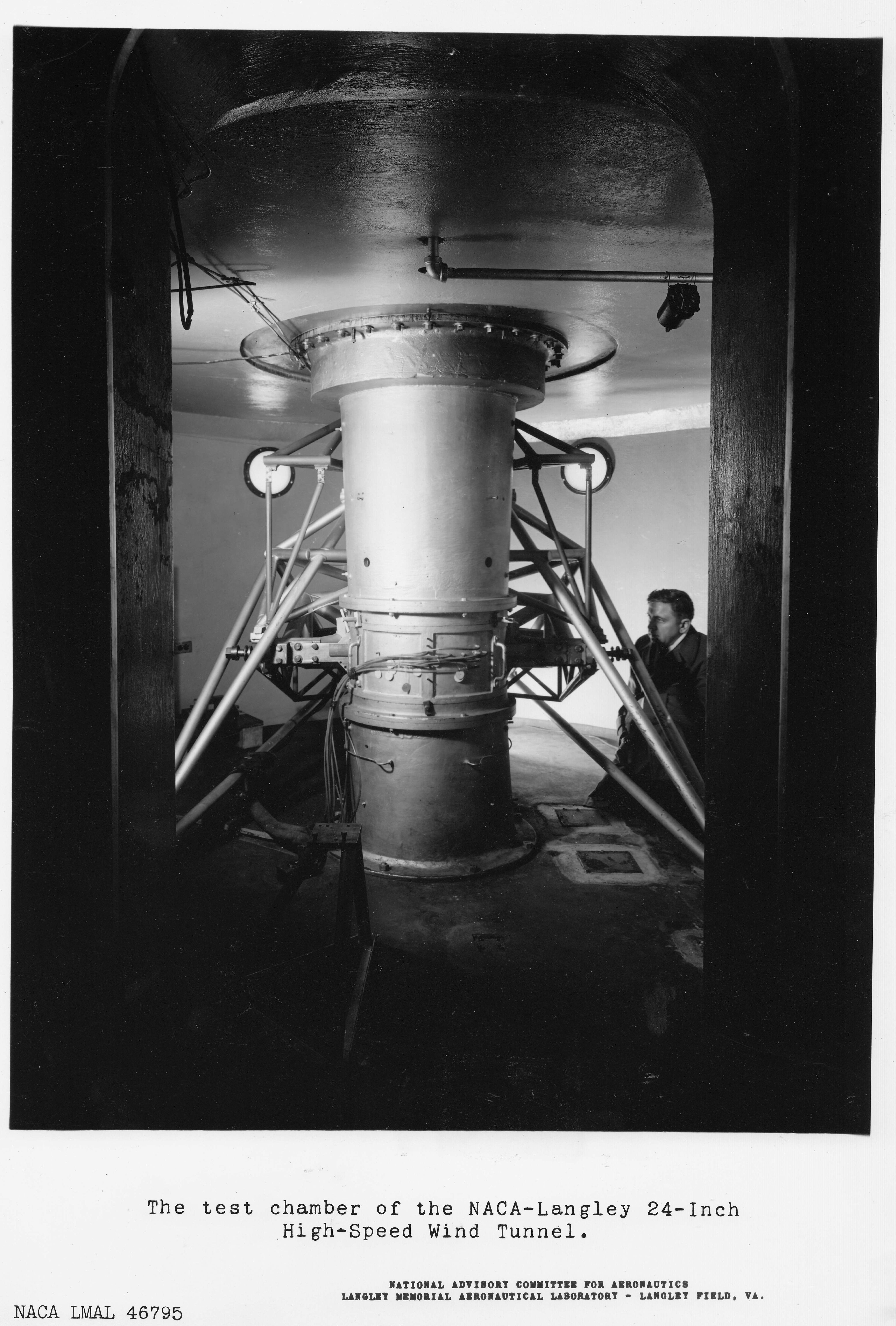
The tunnel test section was oriented in a vertical position and was equipped with Langley’s first schlieren photographic system to examine transonic phenomena such as shock waves at high speeds. The 24-Inch Tunnel was put into operation in 1934, and in 1949 an outer enclosure was added to reduce problems encountered with atmospheric humidity and water-vapor condensation. In 1952 the circular 24-inch test section was replaced with a slotted octagonal 22-inch test section. Both the 22- and 24-inch test sections provided a three-dimensional test capability.
After WWII, national interest in airfoils had greatly diminished, and from the late 1950s to 1970 airfoil research at Langley was constrained to work in the 8-Foot Transonic Pressure Tunnel.
In the late 1960s, however, emerging interest in high-speed airfoils for rotor sections, used for vertical and/or short take-off and landing (V/STOL) aircraft and similar airfoils for civilian aircraft, resulted in studies to convert the existing 22-Inch High-Speed Tunnel (with its three-dimensional test section) to a 6- by 19-Inch two-dimensional tunnel using most of the existing hardware. The resulting tunnel would be used as a workhorse for the new efforts on advanced airfoils.
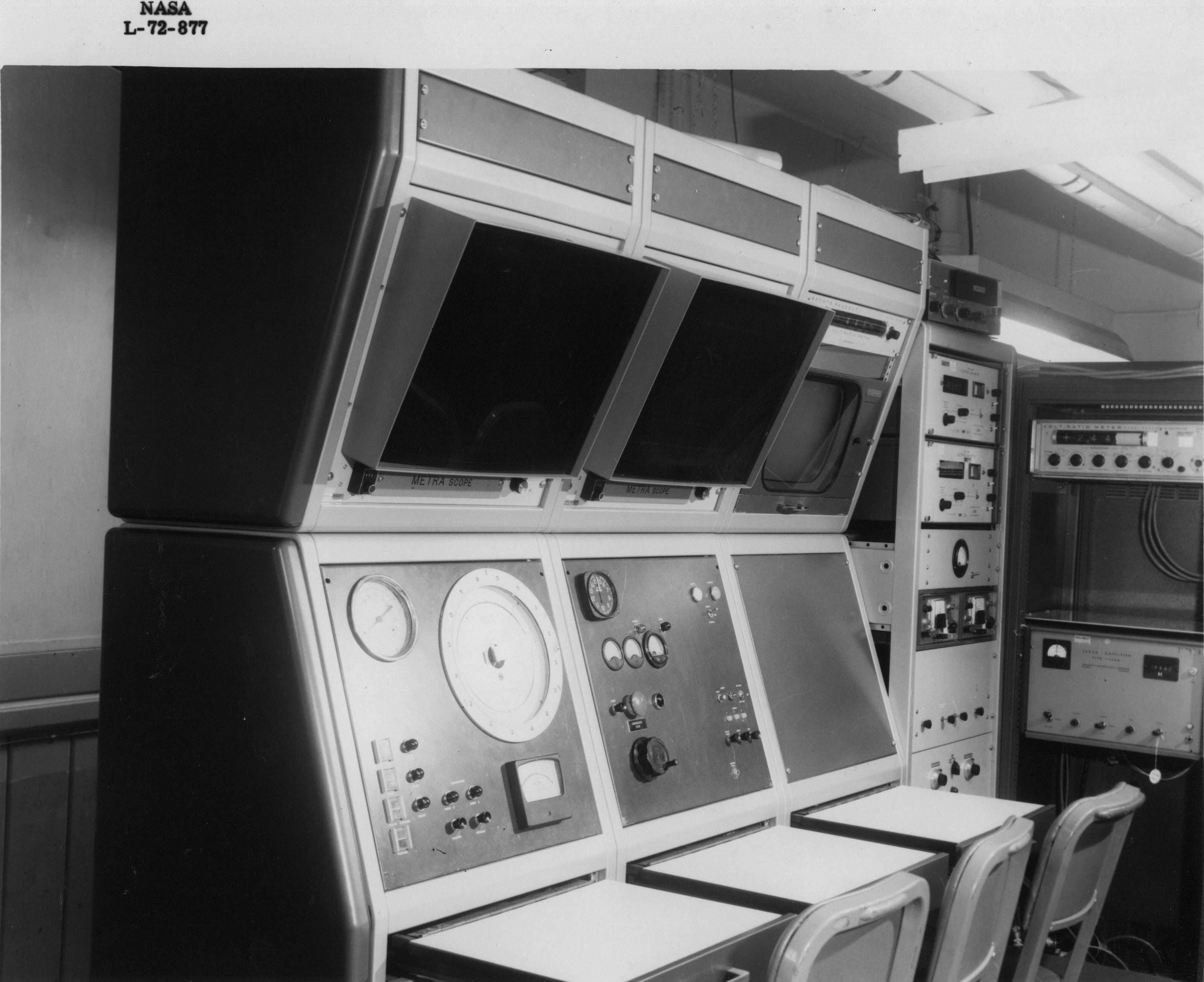
The 6- by 19-Inch Transonic Tunnel began operations in 1971 as a two-dimensional, slotted-wall, vertical wind tunnel powered by a direct blowdown from a tank farm of dry, compressed air. The tunnel was capable of operations at Mach 0.5 to about 1.2, with extensive instrumentation in the form of surface oil flow photographs, schlieren flow photographs, integrated forces and moments, and surface-pressure distributions.
In addition to fundamental airfoil experiments, the facility was used to supply calibration data for the development of computer methods to analyze the effects of slotted walls on aerodynamic data.
It continued in research operations until the late 1990s. Building 585 was demolished in 2014.
Search the NASA Technical Reports Server for additional examples of the work conducted in this facility. Some examples include:
- Tests of Airfoils Designed to Delay the Compressibility Burble
- Application of a transonic similarity rule to correct the effects of sidewall boundary layers in two-dimensional transonic wind tunnels – NASA Technical Reports Server (NTRS)
Related Materials
NASA Technical Note D7182, “Description and Calibration of the Langley 6- by 19-Inch Transonic Tunnel”
1978 Floor Plan