


Small Engine Components Compressor Test Facility (CE-18)
This facility provides the capability for investigating the performance of advanced single- and multi-stage axial and centrifugal compressors and various stage combinations over a wide range of speed, power, and mass flow. The facility consists of a 6,000-hp motor/gearbox that drives a research compressor at speeds up to 60,000 rpm, achieving overall pressure ratios up to 30:1. The compressor can draw air from either an atmospheric intake, a 40-psig pressure source, or a 10-psig refrigerated air system. Air enters the inlet plenum tank, passes through the compressor, and discharges through a throttle valve and cooling water spray before it enters the altitude or atmospheric exhaust system. The rig can accommodate compressors up to 20 inches in diameter. This facility is used to test compressors for gas turbine engines at conditions similar to those found in normal use as well as advanced concepts.

CE-18 Special Features
The facility uses the COBRA data acquisition system to provide on-line and post-run processing. Inputs to the COBRA system include pressure channels (Netscanner), thermocouple channels (DTS), and analog inputs. The facility recently acquired an LDV system which can be used to measure velocities and turbulence throughout the flow path.
A tip clearance control system allows for adjustment of the axial impeller position relative to the compressor shroud. The system supports tip clearance gaps from 0.009 inches to more than 0.050 inches at the impeller exducer at all operating condition of interest and is able to maintain the desired condition with a precision of 0.0001 inches.
Dynamic data streams are acquired via a DEWESoft system at up to 200 kHz. The analog signals, typically from high frequency pressure transducers or strain gauges, are conditioned by Precision Filter cards housed in a 28000F chassis.
CE-18 Facility Capabilities
| Parameter | Operating Value |
|---|---|
| Inlet Air Pressure | Atm to 40 psig |
| Inlet Air Temperature | -20 to ambient |
| Inlet Airflow | 60 lb/s max |
| Atmospheric Exhaust | 14.7 psid |
| Altitude Exhaust | 20-26 in. Hg |
| Rotor Speed | 60,000 rpm max |
| Rotor Size (centrif/ax) | 8 to 20 in. |
| Drive Motor | 6,000 hp |
CE-18 System Instrumentation
| System | Number and Type |
|---|---|
| NETSCANNER (Steady-State Pressures) | 176 Ports of +/- 15 PSID 464 Ports of +/- 50 PSID Barometric Ref (14 used for Facility) |
| COBRA (Facility Low Speed Data System) @ 6.25 – 800 Hz (default 12.5 Hz) |
384 Channels (± 20 mV up to ± 10 V) (340 Available to the Customer) |
| DTS | 96 Type K (13 used for Facility) 96 Type E (30 used for Facility) |
| Precision Filter (28144 cards) Signal Conditioner for kulites / strain gages |
32 channels (2 used for Facility) |
| Dewetron (Facility High Speed Data System) @ Up to 200 kHz sampling rate |
32 Analog Channels Uses Dewe43 modules |
Low Speed Compressor Facility (W-1A)
This unique facility provides for an increased understanding of the complex flow phenomena within multi-stage axial compressors. The facility was designed for a 4-foot-diameter axial flow compressor. Air enters the facility through a filtered roof vent, is conditioned for temperature and turbulence, and then passes through the research compressor. The axial compressor has a removable casing treatment over rotor one and rotor three, which allows for various tip treatment studies. The axial compressor has been configured for injection of air through the stator footring, stator blades, and endwalls to assess flow control. Airflow exiting the compressor is controlled by a throttle valve, close coupled to the collector, and discharged into the atmospheric exhaust system. The compressor rotor is driven by a 1,500-hp variable speed drive motor. The increased size and low speed permits instrumentation to be located directly in the compressor’s complex flow paths. The detailed flowfield measurements will assess emerging CFD codes as well as provide data for the development of flow models required by the CFD codes.
W-1A Special Features
Optical access windows in the compressor casing are used in conjunction with nonintrusive measurements and flow visualization techniques. Data such as pressures, temperatures, and flow angles are measured in both rotating and nonrotating passages using standard instrumentation, hot wires, flow visualization, trace gases, as well as LDV, PIV, and pressure-sensitive paint. Data recording, processing, and display are accomplished through the facility’s distributed data acquisition system, with input data from analog and discrete inputs or steady-state pressure inputs from the Netscanner digitally scanned pressure measurement system.
W-1A Facility Capabilities
| Parameter | Operating Value |
|---|---|
| Inlet Air Pressure | Atmospheric |
| Inlet Air Temperature | Ambient |
| Inlet Airflow | 32 lb/s |
| Atmospheric Exhaust | 0.8 psid blowers |
| Altitude Exhaust | 20-26 in. Hg |
| Rotor Speed | 1050 r/min |
| Rotor Diameter | 48 in. |
| Drive Motor | 1,500 hp |
W1-A System Instrumentation
| System | Number and Type |
|---|---|
| NETSCANNER (Steady-State Pressures) | 384 Ports of +/- 1 PSID Barometric Ref |
| COBRA (Facility Data System) | 128 Analog Channels 112 Available to the Customer |
| Dewetron (Facility Data System) | 32 Channels @ 1-200 kHz |
| Kulites | 16 Transducers +/- 5 PSID |
| Thermocouples | 96 Type E/K |
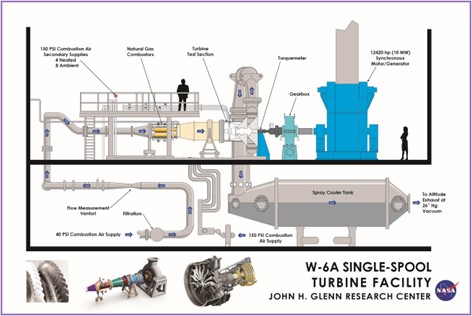
Single Spool Turbine Facility (W-6A)
The W-6A facility performs research in advanced turbine designs and provides the capability for the fundamental understanding of the dominant flow phenomena in multistage high-pressure (HP) and low-pressure (LP) axial turbines. The facility is supplied with 40-psig air, which is then heated by natural-gas fired combustors, drives the research turbine, and exits through a torus-like collector into the altitude exhaust system. Electrically heated secondary air provides simulated coolant bleeds at desired temperature ratios, including provisions for heated air to control shroud growth and rotor clearances. Data from detailed flowfield measurements, unsteady effects, and interaction effects provide better understanding of flow physics through a multistage turbine and provide a database to use in CFD code validation.
W-6A Special Features
The turbine is motored to desired speed by a 12,420-hp synchronous machine and gearbox (7.871:1 ratio). Once at speed, the synch machine transitions from motor to generator as turbine airflow is introduced and the resultant turbine shaft power must be absorbed. The shaft has a 1” bore, which provides the capability to pass wiring from rotating turbine-measurement instruments to a 100-channel slip ring. The data acquisition and display system consists of 512 analog and 576 pressure measurements using ESCORT D and an ESP system. Slip ring measurements include thermocouple, pressure transducers, or strain gage signals. Torque output is measured using an in-line torque meter.
W-6A Facility Capabilities
| Parameter | Operating Value |
|---|---|
| Primary Air Pressure | 40 psig |
| Secondary Air Temperature | 150 psig |
| Inlet Air Temperature | 950°F max |
| Primary Airflow | 27 lb/s |
| Altitude Exhaust Pressure | 2 psia min |
| Rotor Speed | 14,000 rpm max |
| Rotor Size | 52-inch diameter |
| Power Absorption @ Synch Machine | 12,420 hp; 36,217 ft-lb max torque |
| Turbine Torque Limits | 4,600 ft-lb max (@7.871 max gear ratio) 24,000 ft-lb max (@1.51 min gear ratio) |
| Torquemeter | +/- 2,500 ft-lb current configuration +/- 10,000 ft-lb frame capability |
W6-A System Instrumentation
| System | Number and Type |
|---|---|
| ESP | 192 Ports of +/- 15 PSID 64 Ports of +/- 30 PSID 32 Ports of +/1 100 PSID Barometric Reference |
| Escort | 704 Analog Channels 64 Available to the Customer |
| Thermocouples | 144 Type K 240 Type E 96 Channels Available for Any Type |
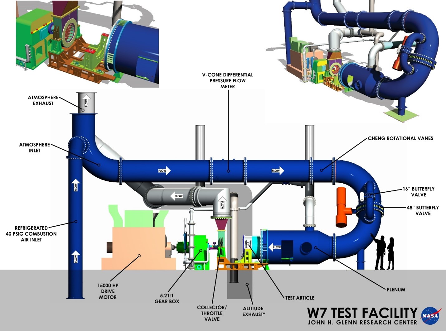
High Speed Multistage Compressor Facility (W-7)
W-7 is currently configured as the High Speed Multistage Compressor Facility in support of testing experimental compressors and fans.
The facility driveline components to support this testing include a 15,000-hp synchronous drive motor and a 5.2045:1 ratio gearbox. Test article shaft speed capability ranges from 1,640 to 18,700 rpm.
Inlet air for a test package can be supplied by several means. Atmospheric air (filtered) is drawn in from outside the facility, or pressurized air can be supplied from the combustion air supply system (20 psig @ 90 lbm/s – nominally ambient temperature). After entering the inlet piping, the inlet air is drawn through a V-cone flow-measuring device, coarse and fine inlet control valves, and the plenum tank for flow-conditioning prior to entering the test article.
Air is exhausted through a back-pressure throttle valve and collector and discharged either to an atmospheric vent, through a low-vacuum blower system (approximately 13 psia), or to the central process altitude exhaust system (@ 2 psia).
The hydraulic control system provides fine metering of throttle valve action, including fast-open capability. The system also provides control for up to five variable stator vane rows. Vane position for each row can be maintained per a schedule based on corrected speed.
W-7 Facility Capabilities
| Parameter | Operating Value |
|---|---|
| Inlet Air Pressure | Atm to 20 psig |
| Inlet Air Temperature | 34 to 200°F |
| Inlet Airflow | 90 lbm/s |
| Atmospheric Exhaust | 0.8 psid blowers |
| Altitude Exhaust | 2 psia |
| Rotor Speed | 18,700 rpm |
| Rotor Size | 22 in. max |
| Drive Motor | 15,000 hp |
Instrumentation and Data Acquisition
W-7 has a COBRA data system for steady-state instrumentation display and recording purposes. COBRA data can be batched and sent, in semi-real time, to remote customers. Inputs to the COBRA system include pressure channels, thermocouple channels, and analog inputs. Pressure channels are provided by Netscanner modules. Thermocouple channels are provided by Kaye isothermal reference blocks with RTD reference temperatures. W-7 also has dynamic data signal capabilities using precision filters for signal conditioning and Dewesoft Dewe43A data acquisition modules.
A multi-axis probe actuator control system (PACS) is available with automated profiles and integrated data recording with the COBRA system.
The facility has a Bently Nevada 3500 Health monitoring system for monitoring the health of rotating equipment including radial vibration orbit proximity probes and accelerometers for each bearing plane. A Bently Nevada ADRE system is available for advanced health monitoring diagnostics. The facility is also capable of using APEX Turbine systems for frequency domain and Campbell diagrams for display and data recording.
The facility has numerous monitoring stations connected to a KVM matrix system that allows researchers and operators to access almost any system display at any monitoring station.
Control room space and cable tray provision to the test cell exists to accommodate set-up of customer-supplied instrument system hardware. Buffered once-per-rev signals, from compressor forward-end instrumentation, are available for customer data systems. Also, a facility laser interlock system is available, if necessary, for customer laser–related systems.
W-7 System Instrumentation
| System | Number and Type |
|---|---|
| NETSCANNER (Steady – State Pressures) | 768 Total Channels 192 Channels @ 0 – 15 PSIA 192 Channels @ 0 – 30 PSIA 192 Channels @ 0 – 45 PSIA 128 Channels @ 0 – 100 PSIA 64 Channels @ 0 – 250 PSIA Barometric Reference |
| COBRA (Facility Low Speed Data System) @ 6.25 – 800 Hz (default 12.5 Hz) |
544 Total Analog Channels (± 20 mV up to ± 10 V) 32 General Use Analog Channels – Control Room 223 General Use Analog Channels – Test Cell 127 Thermocouple Channels Any Type – Direct Connect 92 Thermocouple Channels Type E – Jack Panel 55 Thermocouple Channels Type K – Jack Panel (15 used for Facility) |
| Dynamic Data Signal Conditioning Precision Filters |
64 Channels |
| Dynamic Data Data Acquisition Dewesoft Dewe43A |
64 Channels |
| Probe Actuator Control | 16 Axes |
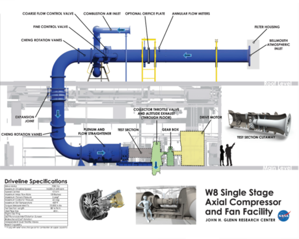
Single-Stage Axial Compressor Facility (W-8)
The Single-Stage Axial Compressor Facility is used to investigate the aerodynamic performance of small-scale fans and compressors with a nominal pressure ratio of 2.5. The drive system consists of a 7,000 hp, 3,600 rpm synchronous electric drive motor and a 5.9:1 ratio gearbox, powered by the Engine Research Building (ERB) Variable Frequency system. The compressor speed can be controlled between 1,860 and 21,240 rpm. An in-line torquemeter rated for 22,000 in-lbs measures power absorbed by the research compressor. The test rig shafting is bored to provide the capability for rotating measurements using a slip ring assembly. A Programmable Logic Controller (PLC) system is used to monitor and control facility operation.
The facility atmospheric air system is sized for a maximum flow of 100 lbm/s. Air is drawn into the facility through a filtered inlet located on the roof of ERB. The air then passes through a flow measurement plane and through inlet control valves that can be used for varying inlet pressure when using the altitude exhaust system. Multiple flow conditioning components installed in a large plenum chamber reduce turbulence and provide smooth flow to the research compressor. The air is pressurized as it passes through the research compressor and then flows through a single or dual sleeve throttle valve into an exhaust collector in the test cell. Air discharged from the exhaust collector is cooled by water spray injection before entering the ERB atmosphere exhaust system (0.8 psid) or the Central Process System (CPS) altitude exhaust system (20 – 26 in Hg).
A 40-psig combustion air source can also supply dry air to the facility. Combustion air passes through control valves to reduce its pressure, through a flow-measuring orifice, and then enters the piping system just downstream of the inlet control valves mentioned above.
W-8 Special Features
The COBRA data acquisition system is capable of monitoring and storing up to 384 individual channels of analog inputs. Additional data can be read and stored digitally from external systems using a wide variety of universal communication protocols. The facility offers a digitally scanned pressure system (Netscanner) capable of transmitting up to 640 individual pressure transducer measurements. The facility is also equipped to measure up to 214 thermocouple measurements. A 16-axis probe actuator control system is used to automatically traverse pressure/temperature probes to obtain flow data as well as rotate and position inlet distortion screens.
W-8 Facility Capabilities
| Parameter | Operating Value |
|---|---|
| Inlet Air Pressure | 5-20 psia |
| Inlet Air Temperature | Ambient |
| Inlet Airflow | 100 lb/s max |
| Atmospheric Exhaust | 0.8 psid blowers |
| Altitude Exhaust | 26 in. Hg vacuum |
| Rotor Speed | 14,000 or 21,240 rpm max (depending on bearing housing choice) |
| Rotor Size | 22 in. max |
| Drive Motor | 7,000 hp |
W-8 System Instrumentation
| System | Number and Type |
|---|---|
| NETSCANNER (Steady-State Pressures) | 256 Channels @ 0 – 15 PSIA 384 Channels @ 0 – 30 PSIA Barometric Reference |
| COBRA (Facility Low Speed Data System) @ 6.25–800 Hz (default 12.5Hz) |
384 Total Analog Channels (+/-20 mV up to +/-10 V) 128 General Use Analog Channels 150 Thermocouple Channels Type E – Ice Point Ref (27 used for Facility) 64 Thermocouple Channels Type E – UTR 32 Telemetry Analog Channels |
| Dewetron (Facility High Speed Data System) @ 1 – 200 kHz |
64 Channels |
Using Our Facilities
NASA’s Glenn Research Center in Cleveland provides ground test facilities to industry, government, and academia. If you are considering testing in one of our facilities or would like further information about a specific facility or capability, please let us know.

/Hubble%20Space%20Telescope%20(A).png)